|
|
| Marlin Sportster, Cabrio, Berlinetta and Roadster builds Enthused or Confused about your vintage Marlin build? Ask away here or show off your build. |

25th January 2012, 14:59
|
|
Senior Member
Enthusiast
|
|
Join Date: Sep 2005
Posts: 354
|
|
 Test drive
I hope to try a run quite soon......as long as my engine spluttering woes are cured,I have still to refit the injectors, and inlet manifold and keep my fingers crossed.Mike, I have sent you the throttle spring, should be with you tomorrow.
|
25th January 2012, 17:33
|
|
Senior Member
Enthusiast
|
|
Join Date: Jan 2007
Posts: 932
|
|
Has everyone received their servo, and has no issues with what they have received? Assuming there are no issues, it is probably time to remove the sticky thread.
Mike
|
25th January 2012, 18:54
|
 |
Senior Member
Enthusiast
|
|
Join Date: Sep 2004
Posts: 1,897
|
|
I have mine and am happy :-)
Robin
|
25th January 2012, 19:36
|
 |
Senior Member
Enthusiast
|
|
Join Date: Mar 2005
Posts: 3,080
|
|
Quote:
Originally Posted by Mike

Has everyone received their servo, and has no issues with what they have received? Assuming there are no issues, it is probably time to remove the sticky thread.
Mike
|
I'm good thanks, but the 'sticky' list is handy to help remember peoples real names!!  |
25th January 2012, 20:48
|
|
Senior Member
Enthusiast
|
|
Join Date: Dec 2005
Posts: 203
|
|
Quote:
Originally Posted by morris
Mike, I think you may be right

The hunt for the sierra/fiesta reservoir may be on after all. I wonder why marlin have it angled up in the first place. I guess because the chassis was sierra based for a while? one of many things that should have been updated with the switch to BMW (such as the build manual). |
The installed BMW master cylinder is fitted at the same angle with the reservoir on it and it dosn't cause a issue. |
25th January 2012, 23:43
|
 |
Senior Member
|
|
Join Date: Nov 2011
Location: Exeter
Posts: 187
|
|
Quote:
Originally Posted by Stuart
The installed BMW master cylinder is fitted at the same angle with the reservoir on it and it dosn't cause a issue.
|
Worth checking what happens if you simulate fluid loss in each line in turn. I think when "level" the reservoirs are designed to retain enough fluid for the "non failed" line. The angle may prevent this and may also prevent the front chamber filling fully due to an air bubble? Also the low fluid float & switch if fitted will not be accurate? Just a thought. Peter. |
25th January 2012, 23:46
|
|
Senior Member
|
|
Join Date: Nov 2011
Location: Exeter
Posts: 187
|
|
Quote:
Originally Posted by Mike
Has everyone received their servo, and has no issues with what they have received? Assuming there are no issues, it is probably time to remove the sticky thread.
Mike
|
All received and fine thanks Mike. Installation temporarily delayed as I have just found a perished and leaking heater hose that goes to the bulk coolant tank which was hidden under the old servo. Still better to find it now rather than half way up the M5 methinks! Peter. |
26th January 2012, 09:53
|
|
Senior Member
|
|
Join Date: Jun 2010
Location: Reading
Posts: 229
|
|
Mike,
I've got mine too. It's still in the box at the moment, but everything is there waiting for the weekend.
Many thanks
Nigel
|
27th January 2012, 21:10
|
|
Senior Member
|
|
Join Date: Aug 2011
Location: Sleaford, Lincolnshire
Posts: 209
|
|
Just a question about removing the output shaft to fit an extended one, does it just unscrew? Mine rotates but does not unscrew and there does not appear to be a locking ring? Am i missing something? John
|
28th January 2012, 09:15
|
|
Senior Member
|
|
Join Date: Dec 2010
Posts: 287
|
|
John, I don,t think it is meant to be removed it can only be adjusted minimally as discussed in previous posts and may need you to make a modification as shown in one of Jasons posts (greatoldone) so that the two operating faces marry up. As Jason has said to me "In an ideal world and with all parts from the same manufacturer then all surfaces will marry up, but........we have a kit car and even then no two are the same"
The servo unit is a sealed one unlike the metro unit.
Hope that helps.
But check out Jasons previous posts for a solution, not the only one I am sure.
|
28th January 2012, 12:50
|
|
Senior Member
|
|
Join Date: Nov 2011
Location: Exeter
Posts: 187
|
|
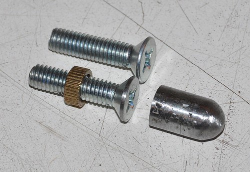
Servo Plunger
Hi John. Attached photo shows the plunger unscrewed from my actuating rod. To do this I fitted the servo assembly loosely into the car, then wedged the pedal down so the plunger protruded out of the housing. Then with a 6mm and 10mm ring spanner I undid the locknut and removed the screw. It wasn’t very tight.
Note! Only use spanners. Don’t attempt to grip the plunger itself with mole grips as it is a vacuum seal surface for the centre rubber seal.
As I don’t have a lathe I am using a pillar drill and ingenuity to make a longer extension plunger to replace the removed part similar to GreatOldOne’s Thread 353 Page 18, but with the 10mm diameter part made separately with a 6x15mm deep threaded hole in it. This will accept a 6mm x 40mm thread cut from a high tensile bolt to maximise strength. The two will be secured together with thread lock liquid. I can use the original lock nut when fitting to the servo rod. Peter.
Quote:
Originally Posted by oaktree11
Just a question about removing the output shaft to fit an extended one, does it just unscrew? Mine rotates but does not unscrew and there does not appear to be a locking ring? Am i missing something? John
|
|
28th January 2012, 17:23
|
|
Senior Member
|
|
Join Date: Aug 2011
Location: Sleaford, Lincolnshire
Posts: 209
|
|
Thanks Peter and Dennis. I see how it all works now and have removed the output shaft.
Obviously, the lathe solution is ideal but we dont all have
access (actually i do own one, a Myford Super 7 but no space for it - its all full of car bits!) and I think Peter's idea is sound. This is not an area with huge loading but obviously it IS safety critical so wants to be well engineered. Actually, with the spacer plate in place the shaft will almost adjust enough for me....but not quite!
Another question! My MC has lugs that will take an M10 bolt. Has anyone fitted M10 machine countersunk bolts to the adaptor plate?
Thanks again, John
|
28th January 2012, 18:57
|
|
Senior Member
|
|
Join Date: Nov 2011
Location: Exeter
Posts: 187
|
|
Servo in at last and just trying the master cylinder in place to check the pipe runs. BUT I seem to have discovered an alarming latent error from build. My understanding of the Sierra dual braking circuit is that the single output pipe from the rear (primary) piston goes to the rear brakes where it divides at the axle. The two output pipes from the front (secondary) piston each go to one front brake. That way if the rear fails you still have the front brakes and vice versa. Does everyone agree? With my system the rear brake pipe goes to one of the front cylinder outlets! Pipes were identified to M/C before disassembly and lengths are different so not an eror by me. Would appreciate any confirmation / comments before I do some major re-routing of the m/c connections to correct this. Peter.
|
28th January 2012, 19:12
|
|
Senior Member
|
|
Join Date: Aug 2011
Location: Sleaford, Lincolnshire
Posts: 209
|
|
Peter,
That is a big no no IMHO. The split system off one chamber is always seperate circuits to the fronts and the single outlet goes to the rear to be "T'd".
If you think about it the way yours is plumbed you stand the chance of losing the rears and one front all at once which is a scary thought...
John
Last edited by oaktree11; 28th January 2012 at 19:25..
|
28th January 2012, 19:23
|
 |
Senior Member
|
|
Join Date: Jan 2011
Location: South Wales
Posts: 378
|
|
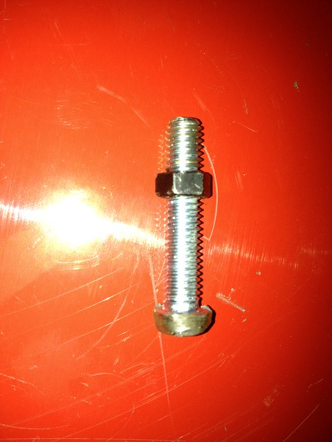
My solution to the problem of getting the servo push rod to work with the M/C plunger
The countersink M6 screw replaces the one supplied in the end of the servo pushrod but the little collet is retained to help prevent vibration slowly screwing it in further. I also had to grind the edge of the screw head a little to get it down to 10mm diameter so it will run smoothly up inside the M/C (compare with the unmolested screw above it)
The bullet was ground to shape from the shank of the M10 bolt I chopped out of the pedal box that was welded in as the accelerator pivot. It has a flat base for the screw to push on.
I had tried to use a much longer bullet with an M6 thread cut down the centre so I could screw some threaded rod in to mate with the servo directly but without a lathe and using a cheap clarke drill press, this is pretty difficult at this scale and I struggle to centre the hole, hence this solution.
It feels pretty solid when pushing the pedal.
One thing I have noticed with the new servo (even without the M/C installed) is that I get a slight clunk when you first push down and then it runs smoothly. it may be because my clevis pin is currently in loose as I'm going to replace with an M10 bolt but I wondered if anyone else had experienced this?

|
28th January 2012, 22:43
|
|
Senior Member
|
|
Join Date: Nov 2011
Location: Exeter
Posts: 187
|
|
Quote:
Originally Posted by oaktree11
Peter,
That is a big no no IMHO. The split system off one chamber is always seperate circuits to the fronts and the single outlet goes to the rear to be "T'd".
If you think about it the way yours is plumbed you stand the chance of losing the rears and one front all at once which is a scary thought...
John
|
Yup! That's what I thought. If the rears had failed it would have given me just one front brake = up the bank, or into oncoming traffic! Scary or what. Good job I found it now.
Attached is the servo plunger made on my small drill press today :-) Peter. |
29th January 2012, 07:07
|
|
Senior Member
|
|
Join Date: Aug 2011
Location: Sleaford, Lincolnshire
Posts: 209
|
|
Peter,
At least it should not be too bad to put your braking system right.
Good job with the plunger - I might try to copy it this morning! - John
|
29th January 2012, 11:59
|
|
Senior Member
|
|
Join Date: Jan 2011
Location: South Wales
Posts: 378
|
|
Pete (V8), that's essentially what I was trying to achieve but with the bullet bit being pretty much the entire length. You must have a better drill press vice than me as I can never get an accurate centre to do this kind of fine work. mine tends to push the piece out of alignment as you tighten it up
|
29th January 2012, 18:01
|
|
Senior Member
|
|
Join Date: Aug 2011
Location: Sleaford, Lincolnshire
Posts: 209
|
|
hmmmm am I being too simplistic or will and M6 bolt with the head ground to a button work just as well as a fabricated part. I had a bash a short while ago (until the cold got to me) and this is what it looks like. I will tidy it up tomorrow - I think it will work fine? - John
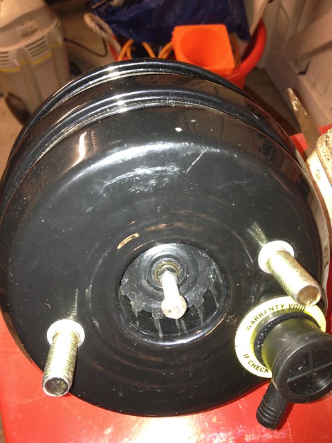 Servo with ground down 6mm bolt
 by oldpropuk, on Flickr
 Servo output mod
 by oldpropuk, on Flickr |
29th January 2012, 18:15
|
 |
Senior Member
Enthusiast
|
|
Join Date: Sep 2005
Location: Northampton, UK
Posts: 1,891
|
|
Yes, that would work - it's essentially what I did with the trial servo. I just cut the end off an M6 bolt and re-used the spacer / cap I already had for use with the metro servo.
Top tip - if you want the head of the bolt to be symetical, mount it in your drill and spin it as you offer it up to the grinding wheel. I did this when I ground the head down on the carriage bolt for my iPod mount. Works great.  |
|
Currently Active Users Viewing This Thread: 1 (0 members and 1 guests)
|
|
|
 Posting Rules
|
You may not post new threads
You may not post replies
You may not post attachments
You may not edit your posts
HTML code is Off
|
|
|
All times are GMT +0. The time now is 05:04.
|


 Linear Mode