Can't think where else to put this.......
Wow!!!!
Regards, Mick
Progress (sort of) at last.
After what seemed to be one of the most depressing winters in my seven decades, I made the effort in yesterday's sunshine and visited the man-cave brimming with enthusiasm.
My modified rear suspension tie bars are at my welders, hopefully ready next Wednesday, and the exhaust mounting kit I ordered from Canley Classics has yet to arrive, so I decided to start work on my 15" MGF 'Minilites'.
I first gave them a good wash with warm water + detergent and left them to dry in the sun while I constructed an impromptu spray booth in my front garden. I then gave the wheels a quick rub over with 320 emery paper, followed by a final de-grease with acetone before commencing spraying with satin black from a rattle can, one of which was sufficient for all five wheels.

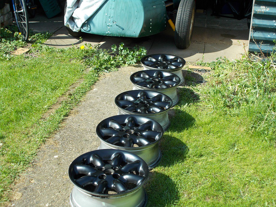
I'm somewhat boracic this month, as I have to pay the balance of my Classic Le Mans trip (I have until Thursday to decide whether to lash out an additional £199 for two parade laps in the A352), but when pay-day arrives I shall get some rubber, by which time I'll hopefully have fitted the necessary Range Rover studs.
Regards, Mick
Progress-ish
After a rest day following my energetic weekend, I decided to offer up my exhaust. I rolled the beast out of the cave, recruited my son and attempted to remove the body - first time this year. It seemed strangely heavy and my son said it felt attached. A quick check revealed that I had left the gear change linkage attached. The M6 bolt that I'd dropped through the clevis and the clevis itself were bent. Aaaaagh! I managed to lever the bolt out with my wrecking bar, and the strangely lightened body came away with ease

.
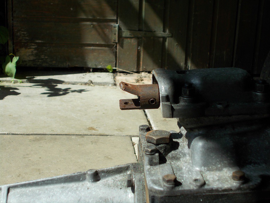
I dug out my pre-owned stainless exhaust and the Canley Classics fitting kit and consulted my Spitfire manual to try and make head or tail of the bits. No luck, not even a diagram

. I offered the long pipe up to the manifold and it sat nicely between the chassis rails, but none of the Canley bits seemed a likely candidate for attaching it to the front diff hanger bridge. Luckily, there was a rubber mounted bracket on it in the correct position already, so I was able to fabricate a hanger from some 3mm galvanised sheet I had knocking about and, using one of the Canley 42mm clamps, secure the rear of the pipe. It was clear then that the back box would have to be suspended from the Monaco's rear 'floor'. Exhaust progress suspended!
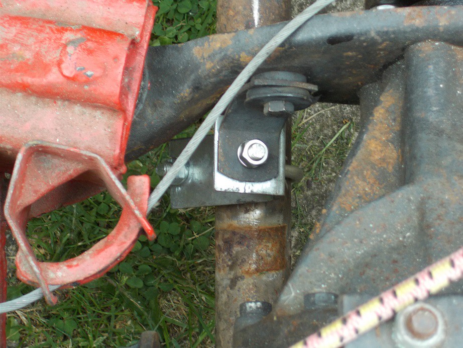
I then turned back my attention to my recently damaged gear linkage. Fortunately, left over from my demon extended A352 gear remote, I had a spare to replace the bent one: ten minutes and it was done

.
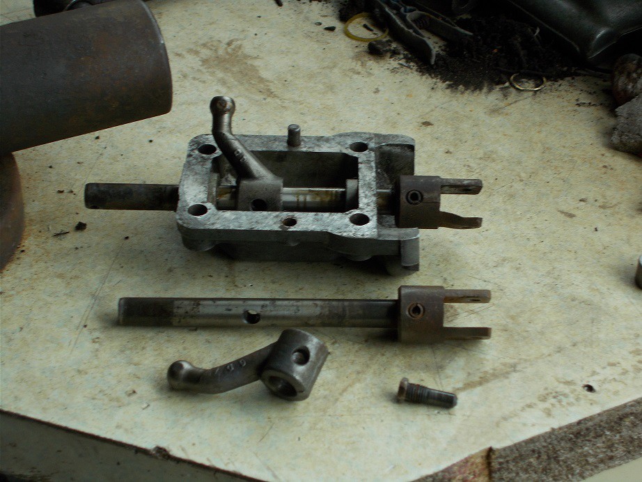
Whilst on gear change duty I then set about putting a little more bend into the lever, which a trial had revealed would result in bruised knuckles on the dashboard in 1st and 3rd. I stripped it out, clamped it in the vice just below the existing bend and, with the knob thread protected with a big nut, cold set it with a 4' length of 1" box slipped over the top. Perfecto!
I then quit whilst I was ahead.
Regards, Mick
Exhausted
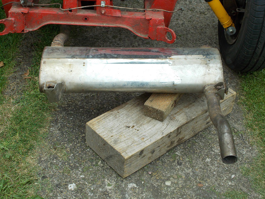
Having fitted the long section of the exhaust, and the long metal fuel pipe which I P clipped to the side of the frame (I forgot to photograph this), I bought two heavy duty exhaust bobbins fondly imagining that the back box would soon be hanging from them. With the body replaced I offered up the box and immediately realised that it wouldn't do
.
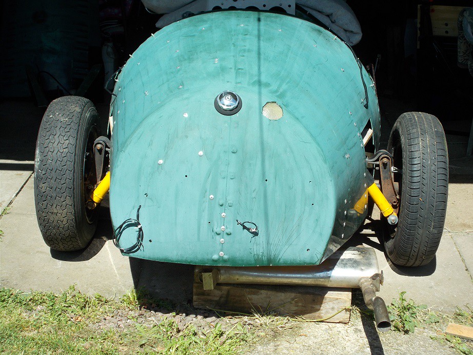
It would be possible for me to construct a bracket attached to the body to support the right hand end but it would be very ugly, but in the wrong way, not in keeping with the overall Monaco ugliness. It also only just cleared the bottom angle bracket attaching the Mini fuel tank to the floor. Hot exhaust and fuel, what could possibly go wrong?
I'll buy a longitudinal back box and offer that up.
Regards, Mick
The Saturday before last, on my way back from the Beaulieu Spring Autojumble, the diff. on my A352 gave up the ghost, resulting in my being towed the last 20 miles home. My go-to for Triumph parts is 'Spitfire Steve' who has met my requirements on many occasions. A 'phone call secured not only a replacement diff. but the longitudinal back box I needed. He kindly exchanged it for the transverse one FOC. Result!

The sole snag with the replacement was the 2" inlet stub which wouldn't mate with the 1 5/8" pipe. I'd hit this problem with the TR6 exhaust I'd fitted to the A352 and had found an excellent supplier of stepped connectors in stainless steel which I again used.
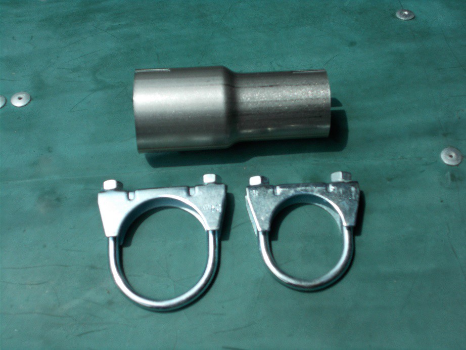
These are made to order and despatched 1st class by return for the princely sum of £10, including the clamps. Top service!
Regards, Mick
The supplier trades as 'everyexhaustpart' on Ebay. His score is 64154 transactions at 99.9% positive.
This is him outside Ebay.
Regards, Mick
The Last Lap - Maybe
The nice man delivered this spiffing Ebay item the other day. The hydraulic seals have been renewed and it was mine for only £75 including carriage. Result! They're Spitfire, for those of you unfamiliar.

I now have everything I need for final assembly, apart from whatever will need doing to the as yet uninvestigated front brakes.
Regards, Mick
Complete Non-sequiter
Can't think where else to put
this. It was my original kit car inspiration. I sold my Lotus VI to a school friend in '71 for £100. He's shunted it from one garage to another for nigh on 50 years without putting it back on the road.
Such a shame, but undoubtedly a sound investment!
Regards, Mick
And still they come........
Here
Regards, Mick
Slim indeed, on that chassis. Were it Triumph based it would be straightforward.
I'm wondering if it's the same one that featured in earlier posts on this thread? I can't be sure from the pictures, but it seems likely.
Regards, Mick
It's possible to get almost anything through IVA if sufficient effort is applied. At present all the modifications required can be reversed once approval is granted, making rather a mockery of the process. I understand that the Westfield Owners' Club has a kit of the necessary parts for hire to get the Lotus XI evocation through.
That yellow Monaco would need some serious work to meet all the requirements, whereas mine is simply a re-body, or 'Radically Altered Vehicle' as DVLA style it. Its unmodified Spitfire underpinnings constitute its identity, irrespective of whatever bodywork is fitted. Witness my A352 which is styled on its post-V627 process V5: Make: Triumph; Model: Spitfire; Body: Sports.

I imagine that my Monaco will be similarly described.
Regards, Mick
No, but......
Afraid not. Perhaps it was
this one, with the new owner popping over to Blighty to show off his (her?) multi million £ new toy?
Seriously though, it's possible that it's the one mentioned at the end of
this post? There are probably a few similar scattered around the country but the likelihood of their being used for trips to Asda, like mine, is remote!
Regards, Mick
Three Months. Blimey!
Yesterday, for the first time in earnest since June 3rd, I ventured down to the deliciously cool man cave to play with the Monaco. After a bit of a tidy up of some boxes of my children's stuff stored there, and a once over with the yard brush, I had to decide on something simple to ease myself back into the build.
I've never really been happy with my upper seat belt eye bolts, positioned as they are to crack the odd vertebra or two in the event of being hit from the rear, so I decided to reverse them, which will allow the mounting plates with their captive nuts to be recessed into the plywood seat back. The belts themselves would have to emerge through the rear deck with this arrangement so I set to measuring and marking where the holes would have to be cut. To make this arrangement tidy, and please the MOT inspector, I decided that ally escutcheons were needed.
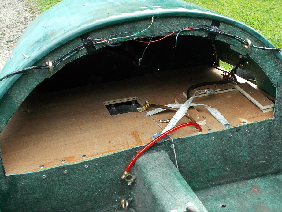
I made a card template, transferred the outline to ally sheet, and tin-snipped out the blanks. I cut the central slots with wood chisels and bent the flaps in the vice by tapping a piece of thick steel through, before drilling the rivet holes.. A trial fit of the belt end plates verified that my measurements were correct. The slightly ragged ends of the slots will have to be dressed in situ.
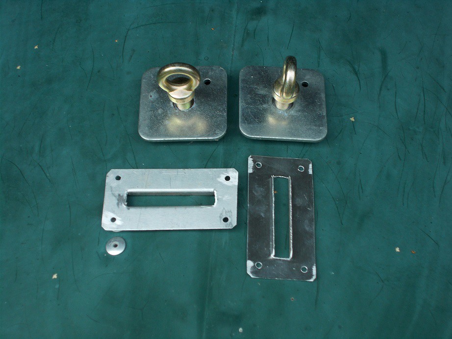
By this time the early afternoon sun was streaming into the cave and the thought of getting into the hooded paper suit to cut the slots in the body decided me to leave that for another day.
I'd long ago realised that, whichever pedal box I used, an access panel would be needed for the master cylinders. After some more careful measuring of the position of the footwell bulkhead and the pedal box, I marked the body ready for cutting which, again, will have to wait for a cooler day.
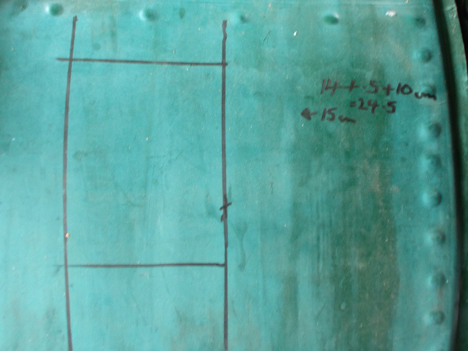
Regards, Mick
A tiny bit more.....
I wandered down to the man cave mid morning yesterday and decided to make a little more progress. Out came the drill and the jigsaw and I attacked the access panel outline, hoping that my measurements were correct. After vacuuming the doom dust, as I call it, and removing the protective gear it was time to offer up the pedal box.

I tried balancing it on bits of wood but it didn't want to play so I strung it up Heath Robinson style. The oversized reservoir on the brake master cylinder made optimal positioning impossible so I removed it, I'll have to substitute a regular sized one. I also disced off the top right hand corner of the mounting plate to make it fit up against the footwell more snugly.

Now happy with the way it sat I put it back on the bench to ponder how I would attach it. The front facing bolts can easily be substituted with appropriately longer ones to pass through the bulkhead with a reinforcing plate on the engine bay side. The vertical facing ones will need a transverse bar attached to the body sides to locate them. This will need to be angle.
By now, the noonday sun was turning the cave into an oven, so I packed up.
Regards, Mick
Hi Colin
No frame, they simply bolt through the thick GRP of the seat back area.
Regards, Mick
Hand In Pocket
I wandered down to the cave yesterday and measured the body width and pedal box mounting area. Logging on to Ebay I bought the necessary 3mm steel plate and 20x20x3mm steel angle. A trip to my local fixings factor, Allcap, and I bought the ten 2" long 1/2" UNF screws c/w penny and split washers I needed. This emporium has never let me down, no matter how obscure the specimen fixing I've presented for duplication, and it's maintained its £4.00 + VAT minimum charge, and all practically on my doorstep. Excellent!
Roll on delivery for further fabrication
Regards, Mick
Pedal Box Progress
My 3mm steel plate having been left on my doorstep whilst I was out
, I was able to crack on yesterday. Before cutting any metal, I made a template of the curvature of the body to ensure a snug fit of the mounting. I used cardboard on the outside and transferred the profile to another piece of pizza carton which, when offered up in the footwell, was acceptable.
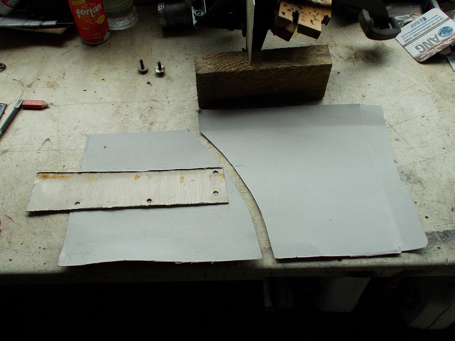
Examining the ally mounting plate revealed that it would be severely weakened once the vertical element (which I'm replacing with the steel) was removed. I cut off a strip, bent it into an angle, rivetted it on, and disced off the redundant section.
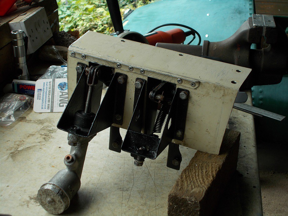
Using the template and the above section I marked, jigsawed and drilled the new plate with the mounting holes centralised.

A little dressing with the rat tailed file and the footwell side of the steel sandwich mounting was temporarily bolted to the pedals.
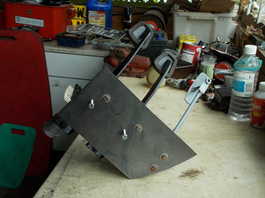
My fillings having nearly been shaken out whilst using the jigsaw, I decided to quit while I was ahead and leave the second plate for another day.
Regards, Mick
I generally use mine for straight cuts, but find the jigsaw's easier for curves.
Yesterday I marked out and cut the second mounting plate which will be on the engine bay side of the bulkhead, creating a metal sandwich.

I then cut the necessary slots in the rear deck and rivetted the two escutcheons in place. The edges of both the slot and the flange needed a little dressing, which I did after taking this.
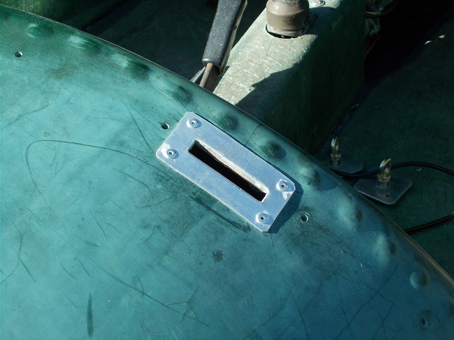
No. 2 son works on Tuesdays, so I couldn't press on with the pedal box mounting as this will have to be done with the body off. Maybe today?
Regards, Mick
Radius Arm Mountings
Yesterday's task was to mark the locations of the forward radius arm mountings on the underside of the body. Like the pedal box, they will have substantial 3mm steel sandwich plates to ensure a sturdy mounting. Ever cautious, I decided to check the wheelbase dimension as I've noticed, when pushing the beast in and out of the cave, that the back wheels move a little fore and aft. The book of words gave the dimension as 83" so I fabricated a demon measuring stick with 1¾" wire ovals protruding at the required spacing. The gap was approximately ¼" too great so I used a ratchet strap to pull things into line. I could then support the mounting plate and attached radius arm gently against the underside with the scissor jack and mark its outline. Repeat for other side.
My son wandered down the garden at this stage to ask if I wanted to take the body off but, once again, it was simply too hot to continue so I packed up.
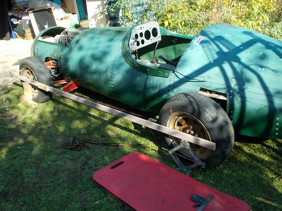
Regards, Mick
Progress of sorts.
Tuesday and yesterday I applied myself to fitting the beefier M10 Range Rover wheel studs to the front hubs. I'd fitted the more straightforward rear ones some time ago and had been feebly putting off this task.
Starting with the offside one (nearer to the workbench), I clamped the disc in the vice and tried to get a socket over the head of the first of the four bolts securing it to the hub. The shape of the casting prevented a very secure location so I substituted a ring spanner tapped on with a hammer and bashed its end to start things off. After a few goes it was proud enough to get the socket on and gently undo it. This worked fine for another two of the bolts but the fourth stubbornly resisted, even after lots of dismantling fluid and heat. I decided to leave it in soak overnight and try again mañana.
Yesterday morning, no change, even after lots of heat. I bit the bullet and used a 4mm HSS bit and my smallest cold chisel to relieve the offending part of the casting. The last bolt then came away easily. Tapping the hub from the disc and drawing the new studs through their holes with a wheel over it, using the new nuts, was simple, as was re-assembly. The near side hub, although identical as far as I could see, proved simplicity itself, the socket being fine on all four bolts. Weird.
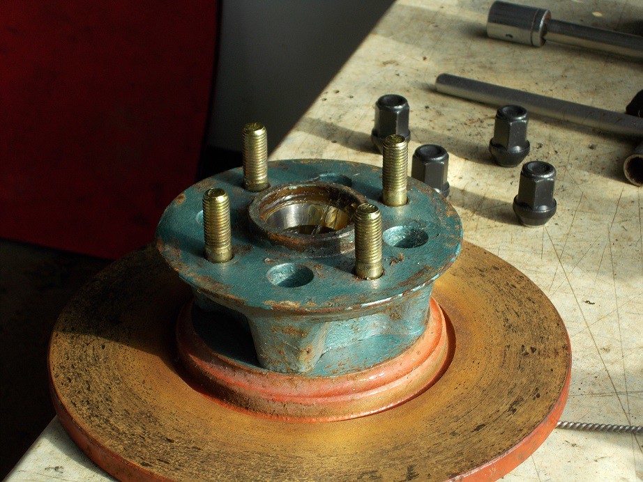
Next job was to run my MGF wheels down to the tyre place, agree on 175 65 15s and leave them there for collection today.
Body removal assistance was was once again unavailable
so I decided to paint my pedal box sandwich plates. My new litre of acetone had arrived earlier so a quick degrease and a few passes with a rattle can had this done.. The paint is matt black but the photo' has lied, showing it as grey. More weirdness.
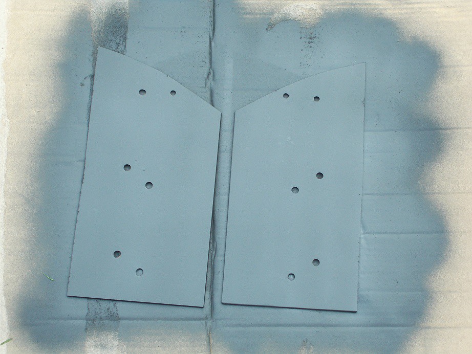
That was it for the day.
Regards, Mick