More Space Planning....
As part of my 'space planning' exercise to make sure everything fits, I've been on a bit of a buying spree....
I bought my Fuel Pumps from Rally Design at the Stoneleigh kitcar show where they had some good deals on their own 'white labeled' pumps. These worked out at about 50% of the price of branded parts. I've opted for a standard Fuel filter because it is designed for the BMW engine, cost effective and easily replaced, if necessary.
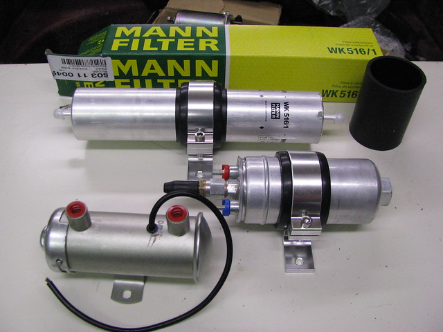 Fuel pumps and filter
 by
marlinpeter, on Flickr
The cradles are from ebay at only £9.99 delivered! Excellent value for money and fitted perfectly.
 High Pressure fuel pump
 by
marlinpeter, on Flickr
Next up is an enclosed Air Filter from Compbrake Motorsport....
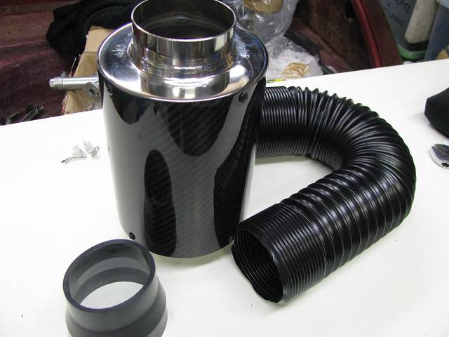 Air Filter with cold air input
 by
marlinpeter, on Flickr
...another bargain for £36!
It's an enclosed cone filter with a cold air input pipe.
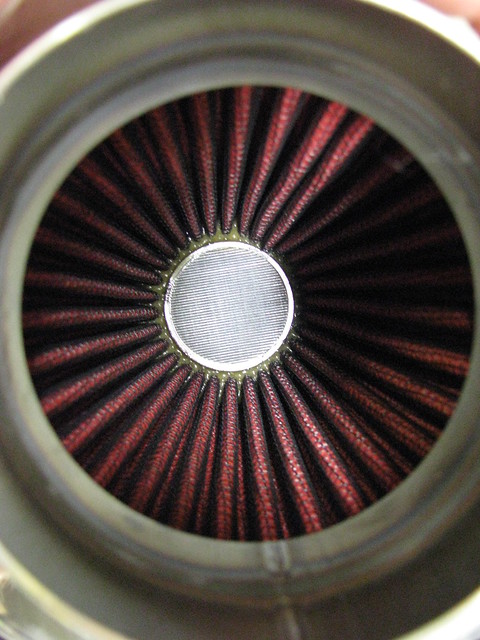 Air Filter internal cone filter.
 by
marlinpeter, on Flickr
For over a year I've had my Dual Circuit brake servo for which I'm now making some mounting brackets...
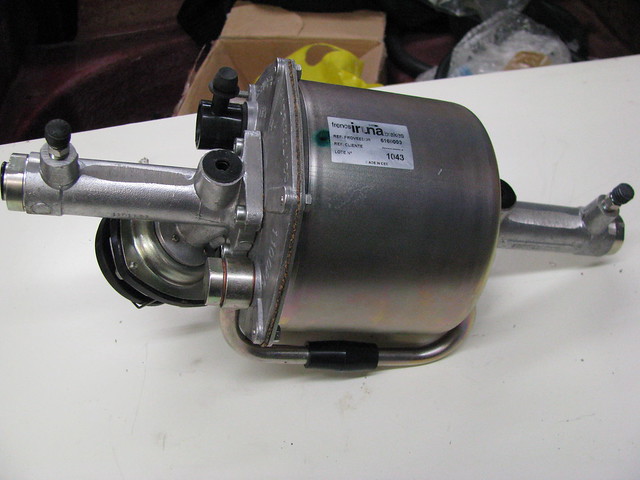 Remote dual circuit brake servo
 by
marlinpeter, on Flickr
I also picked up a really good tool for setting M8 rivnuts...
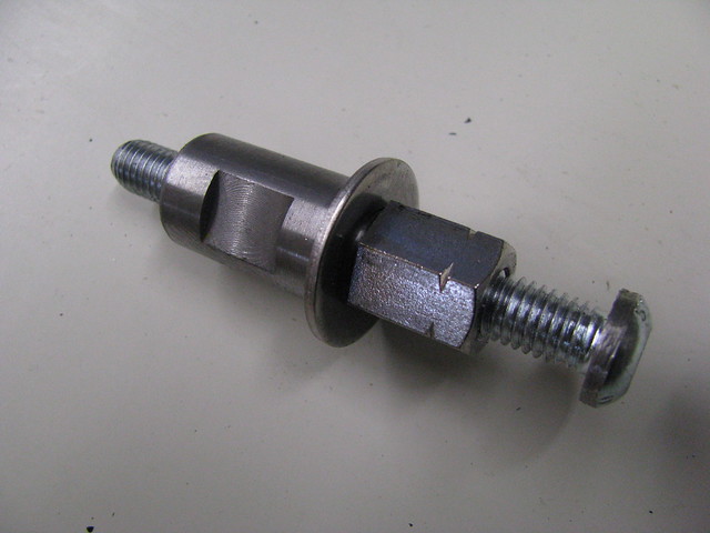 M8 Rivnut / Nutsert tool
 by
marlinpeter, on Flickr
....and it works great.
Finally for now, I bought a couple of heater hose elbows. I had to re-position the heater box further back....
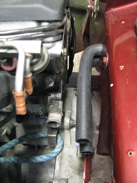 Heater hose elbows fitted.
 by
marlinpeter, on Flickr
This will allow me to move the engine back by 10mm to allow for better sump clearance.
More bits arriving next week....

...peter
Hi Mike,
thanks for the suggestion and explanation.
I've had a a look at mine and found that the MAF is 80mm diameter but my throttle body is only 73mm so swapping the elbow around has it's own challenges. But I will keep your idea in mind as an option if I need the extra clearance. I guess the m50 has a larger throttle body?
...peter
Thanks again for the K&N link and pictures, Peter
Weekly progress....
This week I have been focussing on positioning the dual circuit bake servo...
The Iruna brake servo has one M8 mounting bolt on one end and two m5 bolts the other. It is really designed to be mounted horizontally against a vertical bulkhead. The m8 welded on bolt is designed to take most of the weight and the two m5 fixing points on the other end are to support its weight and stop it rotating. The Royale Sabre does not have too many vertical faces strong enough to support the weight of the servo so I made up some 4mm think mounting brackets. It took a while as it was a kind of 3D puzzle to make them up. The Iruna has a bleed nipple on each slave cylinderso the m8 fixing hole is slotted so I can level the servo once the cars suspension has been set up.
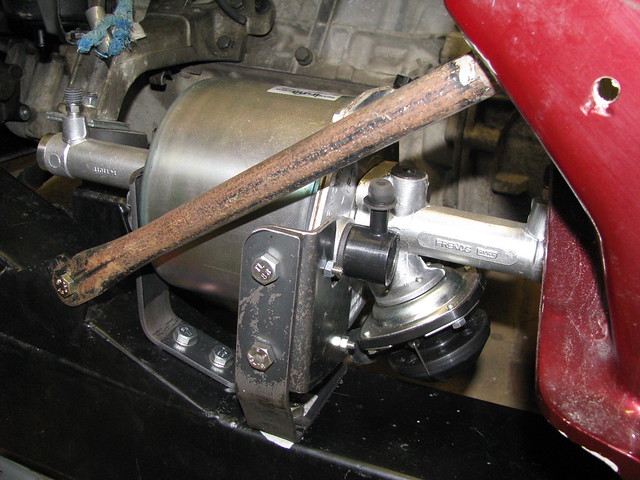 Brake Servo mounting
 by
marlinpeter, on Flickr
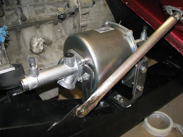 Brake Servo mounting
 by
marlinpeter, on Flickr
Brake Servo support brackets bolted to offside chassis rail.The 'rusty' bar in front of the servo is the the 'A' post support. I've not finished de-rusting and painting it yet. Before final assembly the brackets will be primed and painted and the mounting nuts will be changed to nylocs. Pipe routing will be finalised and installed once I've got other components, like the fuel pump and filter, positioned and the engine is out again.
Another new component arrived this week.........
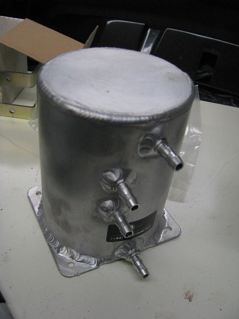 Fuel swirl pot or surge tank
 by
marlinpeter, on Flickr
This is the fuel swirl pot or as it's sometimes called the surge tank. This is to ensure that the HP pump always has a constant uninterrupted supply of petrol. Looks like a nice piece of kit and was hand made by a guy in Wales who advertises on eBay.
Next up I will be mounting the swirl pot, HP fuel pump and filter.....
...peter
Hi Ivan,
thanks for the feedback and yes this is the exciting bit of the build with lots of new goodies

I would be very interested to hear what size and stiffness springs you fitted as I'm definitely going to change mine.
I spoke some time ago to Malcolm Badger at Automotive Creations who now supply and build Sabres. He recommends 8" 300 lb springs which sounds a little on the firm side to me but he does have a lot more experience than me.
cheers, Peter
So there I was in my garage making up some brackets to mount my new swirl pot when I started to ponder on why the donor cars don't have or seem to need swirl pots. I knew that some Ford Sierras had external HP fuel pumps that according Mr. Haynes run directly from the fuel tank so I thought it was time to take a closer look at the fuel tank that came with the Sabre. I'd gaffer taped the holes up, to keep the dust out and stored it away in my garage loft but hadn't looked at it closely.
Sure enough, peering in through the fuel sender hole I can see it has an internal baffle / surge tank.
 Fuel tank internal
 by
marlinpeter, on Flickr
I also bought a sender some months ago which luckily appears to be the right fitting for this tank. The supply and retuen pipes sit inside the baffled tank when mounted.
 Fuel tank sender unit
 by
marlinpeter, on Flickr
Not clear to me what the rubber foot does? Should it have a gauze type filter around it?
 Fuel tank supply and return
 by
marlinpeter, on Flickr
Unfortunately the loom that came with the car didn't have the plug that goes in this connector. Anyone recognize it?
 Fuel sender connector
 by
marlinpeter, on Flickr
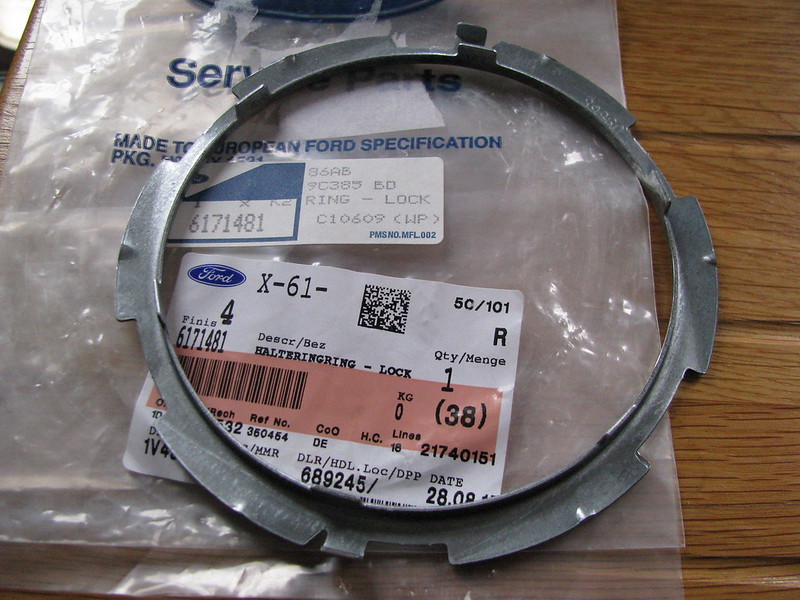
Ford Granada fuel tank sender locking ring. Anybody know the whereabouts of a new one? I've only got the old one that was fitted to the old rusty tank.
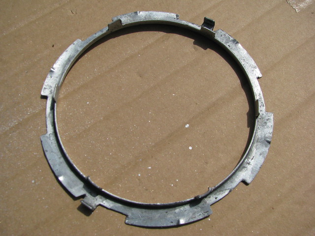 Fuel sender locking ring
 by
marlinpeter, on Flickr
So I think I'm going put the swirl pot and LP pump 'back on the shelf' and keep it simple with just the HP pump.
Whilst I had the tank out of storage I decided to give it a coat of paint....
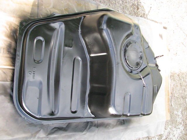 Fuel tank
 by
marlinpeter, on Flickr
Comments and contributions welcome....
....peter
Hi Ivan,
that's great information, thanks for looking it up. I think I'll be getting 8" 300 lb springs then
Do you recall if you used the standard Sierra anti-roll bar?
thanks, peter
Progress update....
Not made huge progress over the last couple of weeks but have spent a fair amount of time working out the locations for the fuel pump and filters plus the routes for the fuel and brake lines.
The previous builder had managed to crush the fuel lines between the body tub and the chassis so I have planned some routes that will hopefully avoid the same issue.
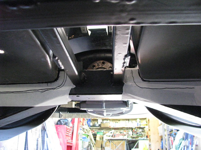 Fuel/brake line planning
 by
marlinpeter, on Flickr
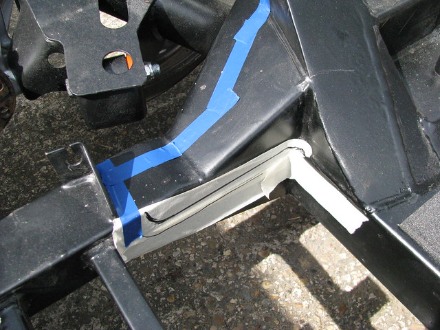 Fuel/brake line routing
 by
marlinpeter, on Flickr
I've also now trial fitted the fuel tank so I can start installation of the fuel lines.....
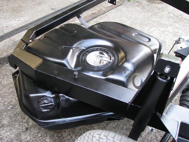 Fuel tank - trial fitting
 by
marlinpeter, on Flickr
I've also been buying up more parts from ebay.....
A high flow rate 100 micron fuel pre-filter.
 High flow fuel pre filter
 by
marlinpeter, on Flickr
A 80mm diameter 180 degree silicone bend for the air inlet.
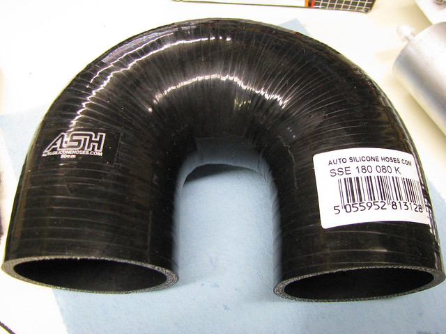 Air inlet bend
 by
marlinpeter, on Flickr
and another pedal box. This one is from an e87 BMW116 that has less offset on the brake pedal compared to the e36 and e46 pedals. Haven't had time to try it properly yet as the body tub is off at present.
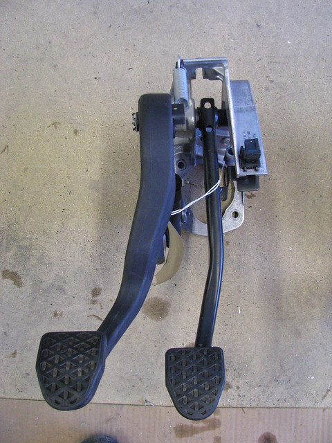 BMW 1 (e87?) series pedal box
 by
marlinpeter, on Flickr
And finally, started making up another bracket, this time to mount the air input filter....
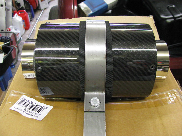 Air box mounting bracket
 by
marlinpeter, on Flickr
Next job is to start the fuel lines and mounting the fuel pump,etc...
...peter
Weekly progress report.....
Well, I did make a start on the fuel lines but then had to wait for some 'p' clips to arrive so went back to finishing the air inlet filter mounting bracket.
I then moved onto painting a number of brackets which I'll grab some photos in a future update.
I found the green house a useful place to let things dry....
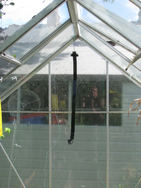 Spray booth?
 by
marlinpeter, on Flickr
The item hanging up is the right hand fuel tank strap which is a standard Ford part with some unusual mounting points with rubber insulated mounts.
The left hand strap doesn't have any part numbers on it so I assume this was supplied by the RMC.
One of the benefits of documenting my builds on this forum is to provide a useful memoir for my own future reference and potentially for other builders, especially when some things are hidden or difficult to see once the bodywork is fitted. So here are some reference photo's of the fuel tank fixing...
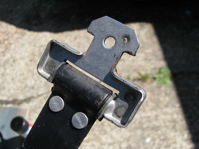 RH Fuel tank strap
 by
marlinpeter, on Flickr
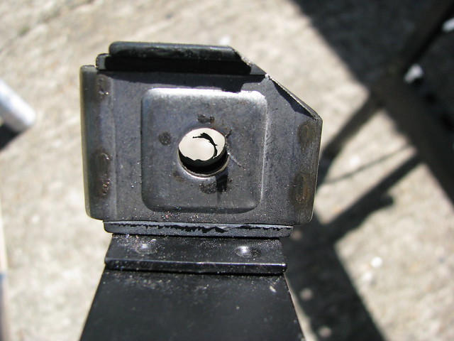 RH Fuel tank strap
 by
marlinpeter, on Flickr
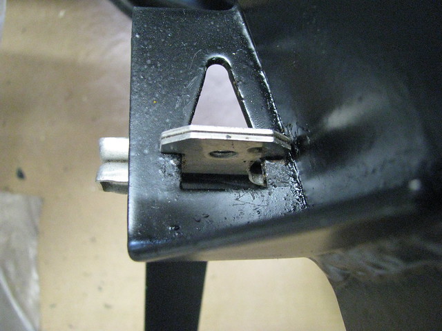 RH Fuel tank strap
 by
marlinpeter, on Flickr
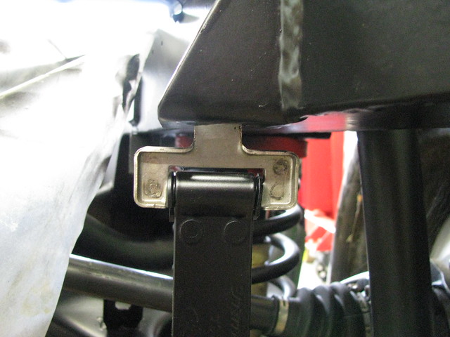 RH Fuel tank strap
 by
marlinpeter, on Flickr
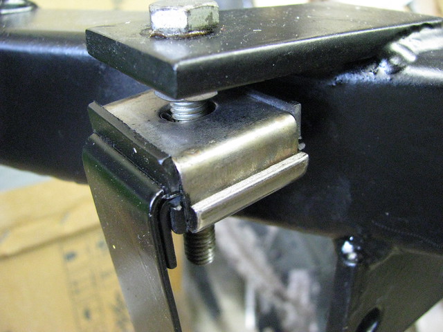 RH Fuel tank strap
 by
marlinpeter, on Flickr
Finally, before completing the fuel tank fitting I decide to give the diff/final drive an oil change. There is no drain plug (as Ford didn't believe it needed changing before the Sierra body rusted away and the car was scrapped). I didn't fancy disturbing the real cover's seal so I used a syringe and short length of plastic windscreen washer hose to remove the old oil. There was very little swarf on the magnetic filler plug suggesting all is well. The old oil wasn't in bad shape and not black as I expected. It was more the colour of a good brown ale whereas the new stuff is a nice amber colour.
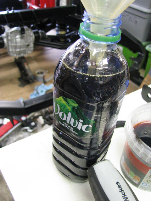 Diff oil change
 by
marlinpeter, on Flickr
It looks a bit darker than it really was in this photo and it may have been unnecessary but as the oil is over 20 years old, it's one of those jobs that is worth doing while it's easy to do without crawling under the car.
Hopefully next weeks pictures will be a bit more interesting....
....peter
Weekly progress report.....
This week I made up a mounting bracket for the pre-pump fuel filter. A couple of stainless steel 'T bolt' hose clamps riveted to a strip of steel. These were amazing value at only £3.18 for both including postage! The trickiest part was drilling the holes in the SS hose clamps.
 Fuel filter mounting
 by
marlinpeter, on Flickr
It's now mounted above one of the rear drive shafts and is mounted so that the filter can be removed from beneath the car with all the bodywork fitted.
 Fuel filter mounting
 by
marlinpeter, on Flickr
I've now started on the fuel lines, photo's next week....
....peter
Weekly progress report.....
Work continued this week on installing the fuel lines...
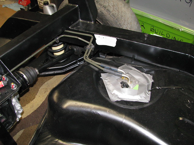 Fuel pipes to tank connections
 by
marlinpeter, on Flickr
 Pre-pump filter
 by
marlinpeter, on Flickr
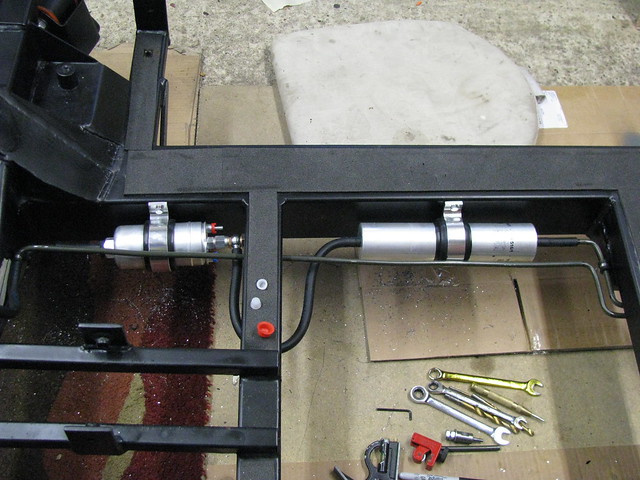 High Pressure pump and filter
 by
marlinpeter, on Flickr
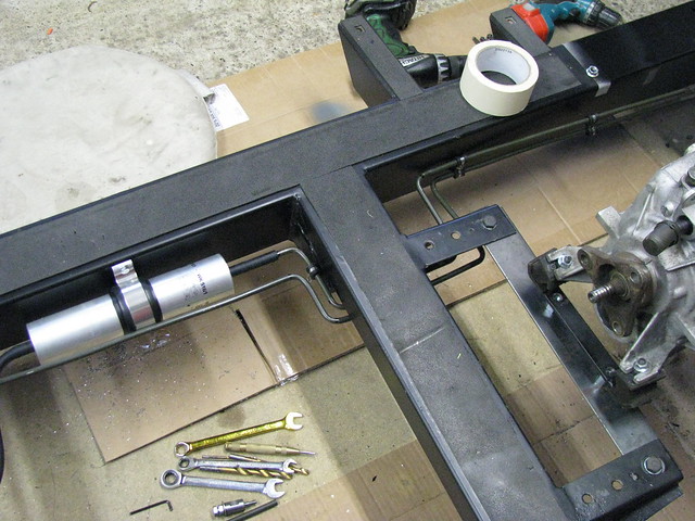 Post Pump filter
 by
marlinpeter, on Flickr
For the flexible sections of the fuel system I'm using Cohline 2240 which is an FPM/ECO hose and it's even better than the so called 'R9' hose and can withstand 100% Ethanol. It's specified and used by BMW, VW, etc.
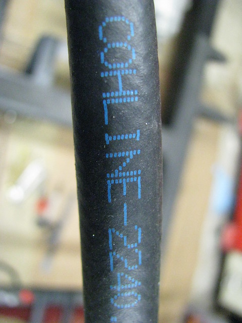 Rubber fuel hose
 by
marlinpeter, on Flickr
For the hard lines I'm using Poly-Vinyl Flouride (PVF) coated dual wall seamless steel fuel pipe. Steel pipes are resistant to corrosion from Ethanol in E10 petrol.
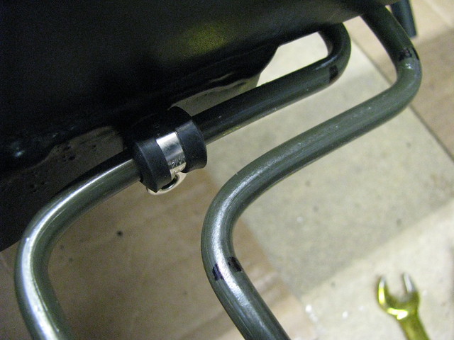 Fuel pipes
 by
marlinpeter, on Flickr
The downside of steel fuel pipes, as we all know, have a tendency to rust from the outside and unfortunately the hand pipe bender I'm using has scratched the coating off in places. So once I'm happy with all the routing and mounting points, I'm going to strip it all off and give the pipes a coat of paint. I also need to de-burr all the ends and blow out any swarf before refitting with the hose clamps.
The installation of the fuel lines has taken longer than anticipated due to the rather torturous route needed to avoid chassis members and the body tub but I'm getting to the end and can start on the brake lines next....
...peter
I've just taken another look at the spec for the steel fuel lines and found that beneath the PVF coating is a zinc plating layer so some scratches in the PVF coating may not be a big issue. For anyone interested this is the manufacturer...
http://agscompany.com/product-category/brake-fuel-transmission-lines/poly-armour/
I've now left an offcut out in the rain to see how well it survives.
Thanks for the feedback, Swifty. I'm glad you are enjoying my updates.
Thanks, Ivan.
The reason for the question was that I have been reading old ROC newsletters from 1994-1997. Early in the life of the Sabres build history the clubs technical rep and the manufacturer (John Barlow) thought that the standard ARB was deemed to be too stiff and recommended grinding some flats on the ARB to reduce its torsional rigidity. That was until in 1997 when one builder who had followed this advice (in the build manual!) had his car fail its MOT as a deliberately modified ARB is (or was then) a failure point.(This was pre-SVA when cars needed to be MOT'd before registration) I haven't found the end of the story yet but in 1997 the ROC technical advisor and the RMC withdrew this recommendation. Luckily the original builder of my car had not modified the ARB.
I think I'll stick with what I've got until I get the car on the road when I can see how it handles with the the weight of the BMW engine.
(small) Progress Report...
There doesn't seem to many build reports on the forum at present and my progress is not very exciting but here's what I've been up to over the last couple of weeks.
I spent a not very exciting day cleaning up the rear brake caliper carriers. They were badly painted by the original builder but had also rusted!! I had to start with some old fashioned paint stripper and then cleaned all that mess off followed by de-rusting and cleaning up with Scotch brite and lots of elbow grease.
I then gave them a coat of Hammerite Smooth and left them in the greenhouse to bake hard.
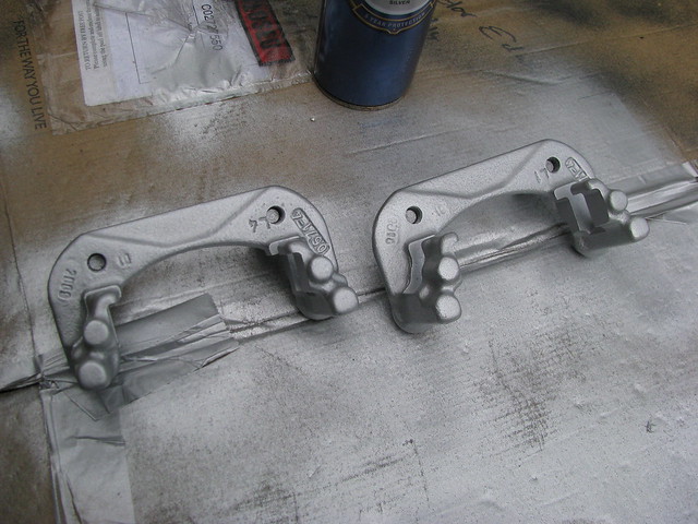 Rear brake caliper carriers
 by
marlinpeter, on Flickr
I have bought some Pagid recon brake calipers as I didn't fancy rebuilding the old ones because the Sierra calipers have a fiendishly complicated handbrake mechanism which, despite being well described in the Haynes manual, still looked like a potential nightmare. The calipers are very pitted and must have been very rusty before being recond but do have new pistons fitted. They came painted but a bit thin so I couldn't resist giving them an extra coat of paint.
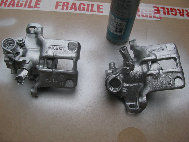 Rear brake calipers
 by
marlinpeter, on Flickr
And I bought a new set of sliders and dust covers....
 Rear brake caliper sliders
 by
marlinpeter, on Flickr
I've also started installing the brake lines. I'm using Automec Cupro Nickel tubing. I was worried that this would be more difficult to flare than pure copper but it turns out is very easy to bend and flare.
It sounds strange but I started in the middle of the car and will work back and forward from this point. First up to be fitted was the Ford rear brake deceleration valve.
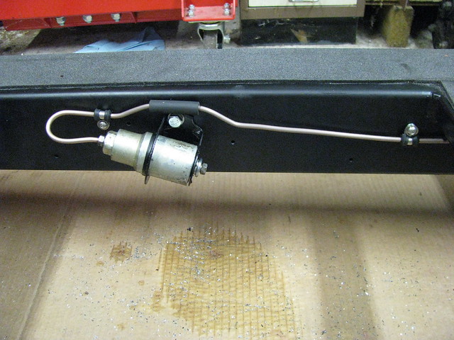 Sierra deceleration valve
 by
marlinpeter, on Flickr
The rear brake deceleration valve reduces brake pressure to the rear brakes under deceleration force. It's supposed to stop the rear brakes locking up when braking hard. There is a heavy weight inside that slides forward shutting off the supply to the rear brakes. The short rubber hose is just for protection.
I then had the challenging task of bending a length of tubing to follow the path back to the two way splitter that divides to the two rear brake calipers.
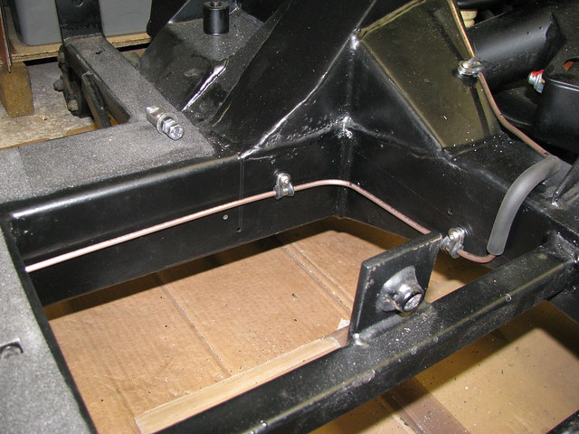 Rear Brake line routing
 by
marlinpeter, on Flickr
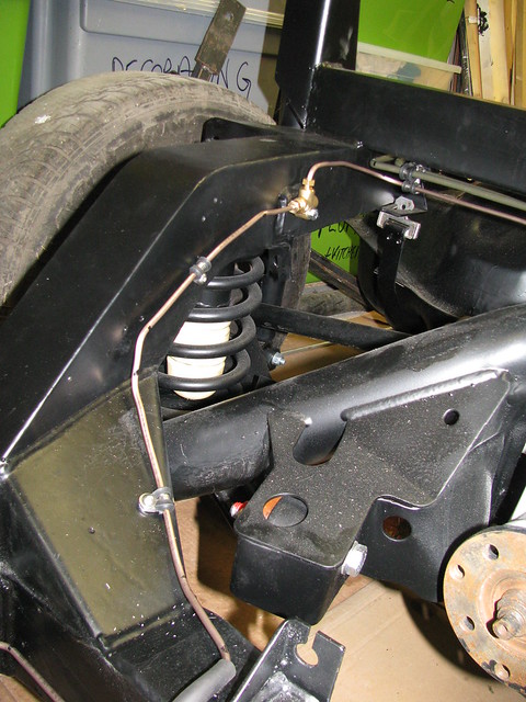 Rear brake line to splitter
 by
marlinpeter, on Flickr
The original builder's mounting position was a bit high and made the right angle out of the top a bit challenging. (Having now studied this photo, I think I'm going to move the splitter down a bit.)
Well that's all for now and unfortunately I've embarked on repainting all the window frames on our 17c cottage, so car building will be limited to spare time when it's raining

...peter
Progress report....
Yeah, the rain over the past few days means I've been able to crack on with the brake installation.
But firstly, I've had a new handbrake cable shortened by Speedograph Richfield. Excellent fast service including test certificate (COC). I've had it shortened by 750mm as specified in the RMC build manual for a Sierra cable.
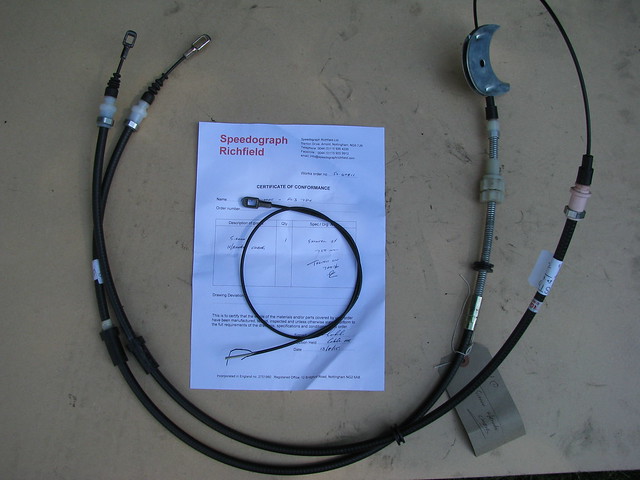 Shortened handbrake
 by
marlinpeter, on Flickr
The new termination is slightly different to the original but seems to fit and work OK.
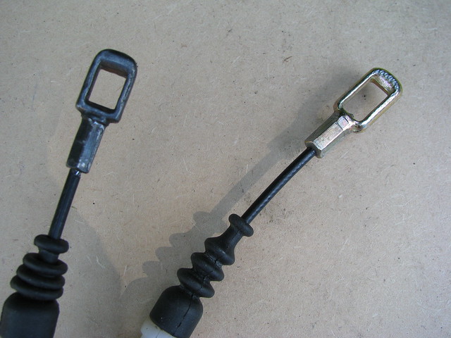 Shortened handbrake
 by
marlinpeter, on Flickr
So on with the rear brakes...
 Carrier, slide pins and new disc
 by
marlinpeter, on Flickr
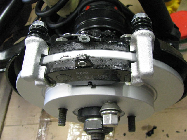 Brake pads
 by
marlinpeter, on Flickr
 Caliper installed
 by
marlinpeter, on Flickr
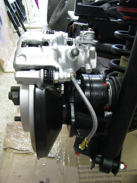 Rear nearside brake
 by
marlinpeter, on Flickr
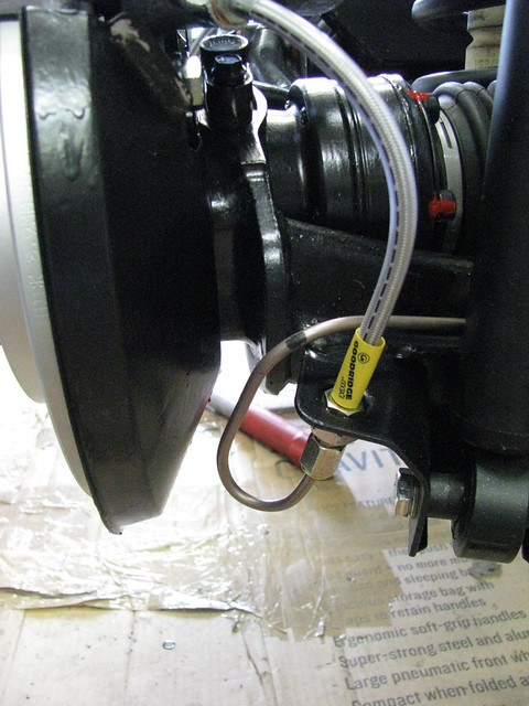 Rear nearside brake line
 by
marlinpeter, on Flickr
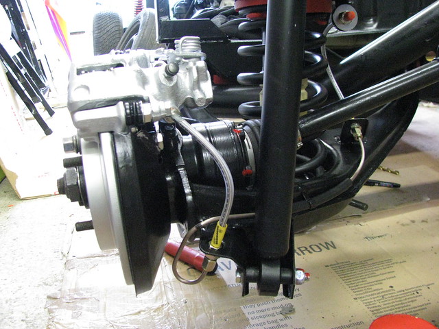 Rear nearside wishbone hard line
 by
marlinpeter, on Flickr
Now it's back to the house painting....
...peter
Update....
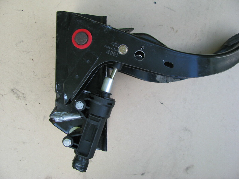
My earlier pedal box trials centered around replacing the original Ford Sierra pedal box with a pedal box from a BMW e46. These are nicely designed assemblies but required the modification of the Sabre mounting cross member and the pedal positioning was not ideal. Whilst pondering one day and looking at all the pedal boxes and pedals I have accumulated it occurred to me that it might be possible to mount a BMW clutch master cylinder to the original Sierrra pedal box which was designed for a clutch cable operation. I first removed all the parts associated with the cable connection and some parts of the pedal. I was then able to mount the BMW M/c on two 6mm spacers. (the box section spacers are temporary as I didn't have any suitable round tubing to hand). I also need to make and fit some nylon spacers each side of the m/c piston
eyelet.
 Clutch Master Cylinder
 by
marlinpeter, on Flickr
My first trial was using the hole you can see furthest from the pivot (red bush) but this resulted in about 5" pedal movement so I drilled another mounting hole nearer the pivot and this gives me about 6" pedal movement which is more in line with a BMW pedal box. Shown hear in the fully depressed mode.
 Clutch Master Cylinder(down)
 by
marlinpeter, on Flickr
Here the pedal is shown in the rest position. I need to devise and fit some upper and lower mechanical stops to avoid damaging the master cylinder and find a way of adding a return spring but the overall concept does seems to work ok.
 Clutch Master Cylinder(up)
 by
marlinpeter, on Flickr
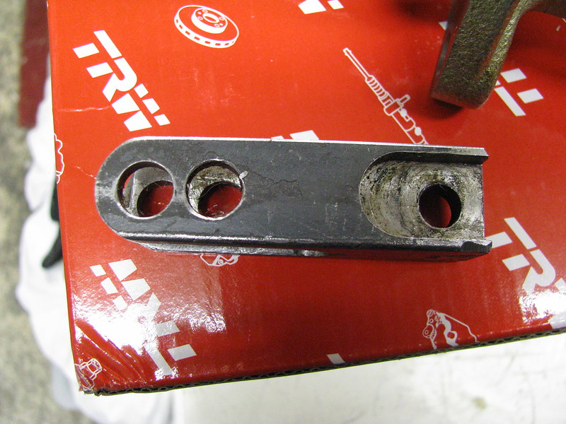
Because I'm using a remote dual circuit brake servo I needed to find a master cylinder with a fixed pushrod to attach to the brake pedal. This one seems to fit the bill and is from a Triumph Spitfire 1500.
 Dual circuit master cylinder
 by
marlinpeter, on Flickr
This pushrod extension was provided by Marlin to extend a Metro servo pushrod. I plan to use it to extend the Spitfire master cylinder pushrod and attach it to the Sierra brake pedal.
 Master cylinder push rod extension
 by
marlinpeter, on Flickr
And like the clutch, I need to add a return spring, etc.
Totally unrelated, I've bought some more seats.....
Slight change of direction. I had already bought a pair of Mk1 MX5 seats but they don't have the shoulder high seat belt supports. My Sabre chassis has rather low seat belt mounting positions that would fail the IVA regulations. The Mk3 MX5 seats have seat belt supports that raise the turning point. I believe the IVA will accept this as a solution as long as the seats are designed to take the forces.
 Mazda MX5 Mk3 seats
 by
marlinpeter, on Flickr
On first look they look like they will fit OK but I'm not sure the design suits the car?
I've also been able to source a new Granada fuel tank locking ring from a parts supplier in the Ukraine! (autopartmaster)
 New fuel tank lock ring
 by
marlinpeter, on Flickr
Isn't the internet a wonderful thing!!
....peter
Pedaling along.....
I've finished work on the pedal box.......
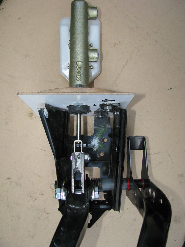
The brake master cylinder has been lengthened with the Marlin supplied extension.The Sierra pedal box needs a good clean up and repaint.Pivot bolt needs to be 10mm longer.
 Sierra Pedal box and master cylinder
 by
marlinpeter, on Flickr
This is the Triumph Spitfire 1500 brake master cylinder mounted to the Sierra pedal box. The 3.5 mm hardboard is simulating the GRP bulkhead on the Sabre body tub. The 6mm thick MDF disc will be replaced with a 6mm steel disc.
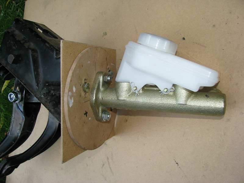 Brake Master cylinder
 by
marlinpeter, on Flickr
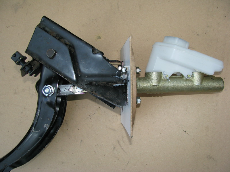 Sierra Pedal box and master cylinder
 by
marlinpeter, on Flickr
Alignment is looking good but the pedal box could do with moving up about 5mm in the final solution.
If fitted return springs to both the clutch and brake pedal.
This is the brake pedal with a BMW spring.
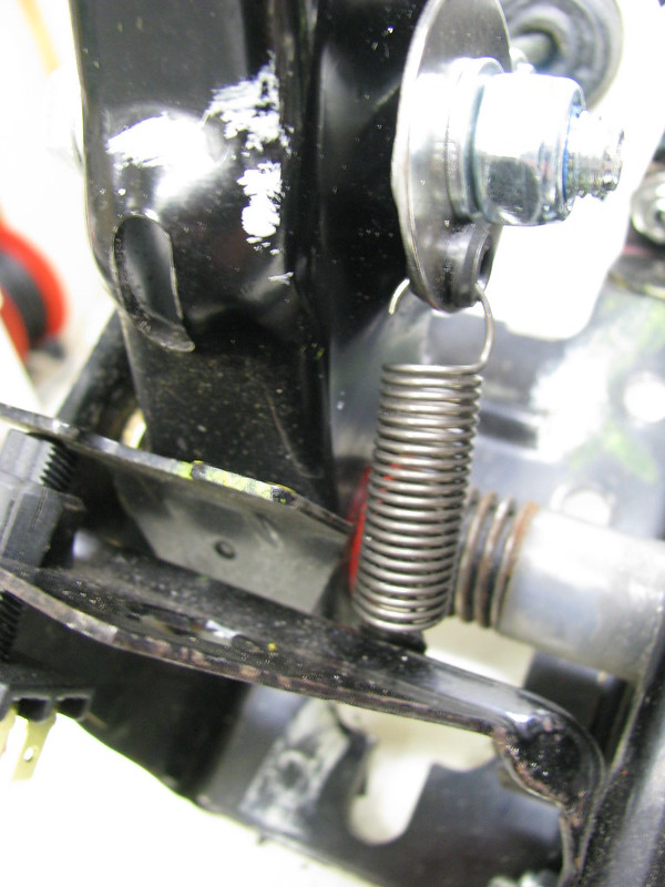 Brake Pedal Return spring
 by
marlinpeter, on Flickr
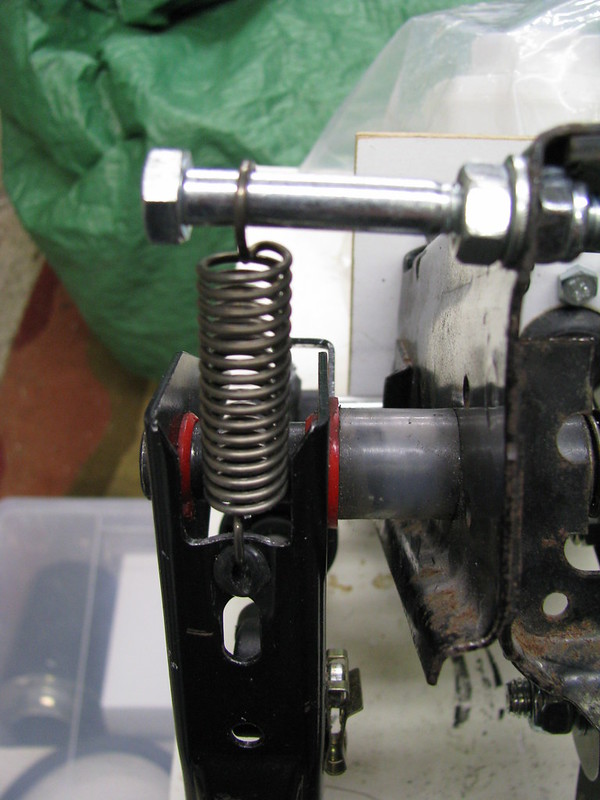 Clutch Pedal return spring
 by
marlinpeter, on Flickr
The clutch spring is a Rover part found in my box of bits.
Modifications to the Sierra pedal box are now complete so it's now stripped down for a repaint.
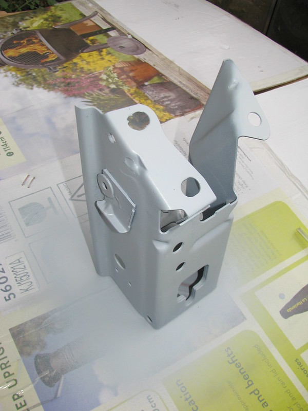 Pedal box painting
 by
marlinpeter, on Flickr
....peter
Thanks Amir, your feedback is always welcome.
Glad you're enjoying the updates, here's the next one........
The Spitfire brake master cylinder pre-dates the introduction of brake fluid low level warning light switches. The BMW cap has a switch but the thread is different to the Spitfire reservoir. Luckily the BMW cap is made with a separate locking ring so I was able to cut a hole in the Spitfire cap.
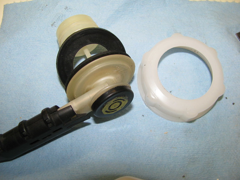 Brake fluid level switch
 by
marlinpeter, on Flickr
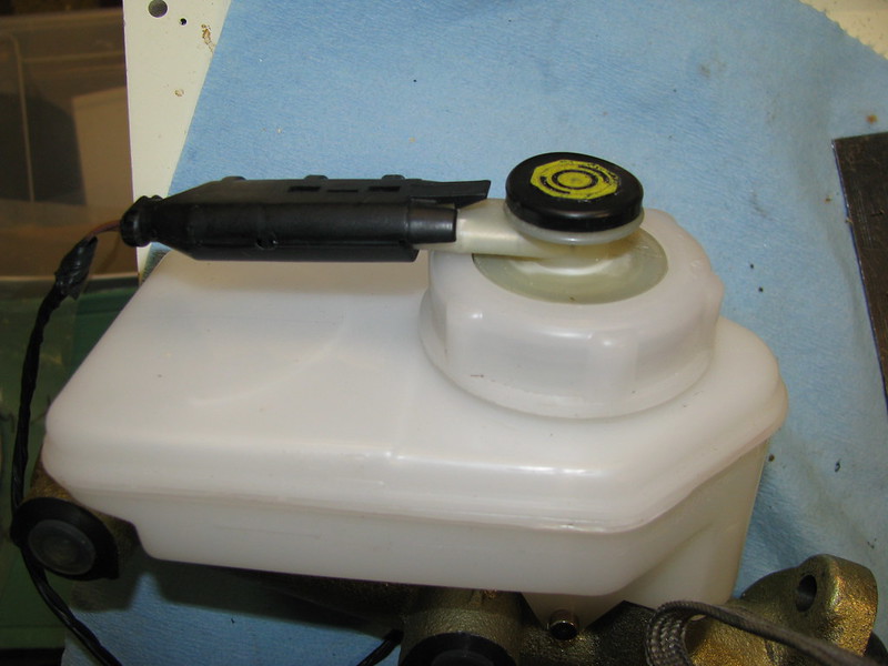 Brake fluid level switch
 by
marlinpeter, on Flickr
My thoughts have now turned towards the exhaust system. Re-use of the e36 donor exhaust system has a number of benefits in terms of being matched to the engine, emissions, sound level and cost. So I've positioned the exhaust under the car to take a look at how it looks. The good news is that it starts on the right side of the car and ends up with the rear box in roughly the right position.
 Exhaust initial trial
 by
marlinpeter, on Flickr
The rear box is in, roughly, the right position and is clear of the rear suspension and fuel tank.
 Exhaust initial trial
 by
marlinpeter, on Flickr
Rear box currently projects about six inches from the rear chassis rail. The Sabre rear bumper sits about 3" from the rear chassis member so I need to loose about 3" in the overall length.
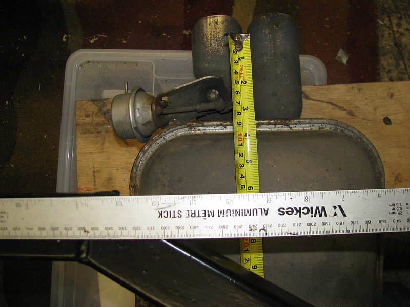 Exhaust initial trial
 by
marlinpeter, on Flickr
The Cats sit centrally below the prop shaft tunnel
 Exhaust initial trial
 by
marlinpeter, on Flickr
I need to design a central support for the system to hang from. (It's currently hanging from that bit of blue rope).
 Exhaust initial trial
 by
marlinpeter, on Flickr
The front pipes to manifold is the biggest issue. With the exhaust slung under the chassis rails it is approx. 7cm too low to meet the manifold. I plan to try some jetex bends to raise the pipes up to the manifold.
 Exhaust initial trial
 by
marlinpeter, on Flickr
Next step is to order some Jetex bends and joining sleeves.
...peter