MadaboutKitcars

Build Stories are assembled automatically from a build thread's own author, in their own words and order — see all featured builds.

Mick O'Malley's Moss Monaco

By Mick O'Malley · 282 updates · Jan 2017 to Nov 2023

Read the full original thread (with everyone's replies) in the archive →

October 2017

8 Oct 2017, 8:44am Mechanical Overhaul
Just a Quickie

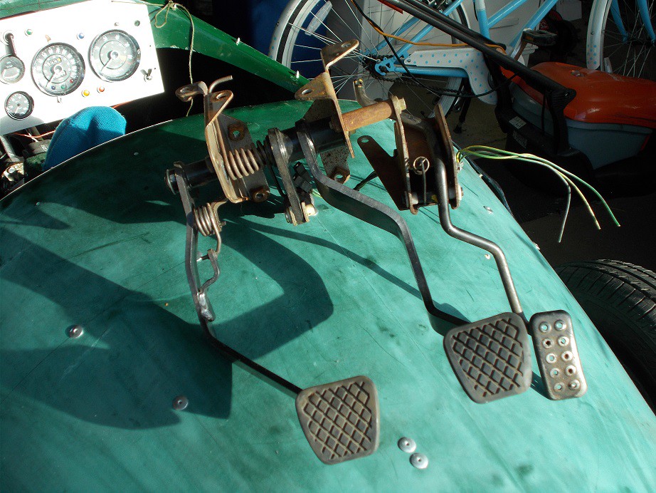
On Friday, the nice man delivered my latest Monaco-related Ebay purchase. After scrolling through pages of pedal box search results, and being unpleasantly surprised at the cost of new ones, I hit on this from an MGF. It's eminently adaptable and a further search revealed that matching new master cylinders are reasonably priced. Result, especially as it was only £17.50 including postage!


Regards, Mick
10 Oct 2017, 4:55am Engine Chassis and Body Electrics Interior & Trim
Almost there. Maybe.

Before Sunday's sortie to the Cheltenham Literary Festival (two of my moto-travel friends were giving a talk promoting their latest books), I managed a couple of hours or so on the project. The fruits of my labours were more P clips made and riveted in position along the engine bay and over the nose cone for the driver's side gubbins.

Yesterday I started by drilling the holes for the wires which will run into the headlamp pods and fed the wires though. I'm leaving them un-grommeted until the loom's completely wrapped. This left the indicator wires looking rather lonely so I decided to fabricate mounting brackets for the L488s. I decided to have them mounted on the sticky-out bits of the frame where I'd trimmed off (following DVLA guidelines) the redundant parts .

Using the trusted CAD method I soon had their profiles transferred to aluminium sheet. The grommet-sized bit was still in the drill so I made starter-holes and used my 'left hand cut' tin snips to enlarge them to the marked size, just. The holes were about the limit in smallness for this method. A couple of minutes with the bench grinder and a rat-tail file, plus a quick bend in the vice and they were ready for mounting. I used regular 4mm rivets to attach them.


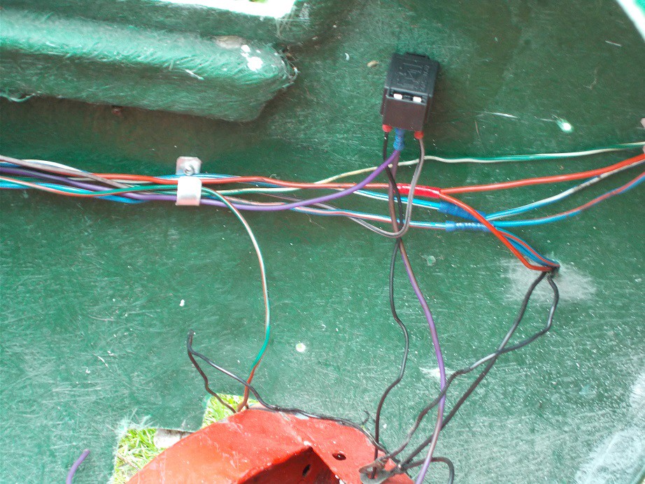
The other day I had ordered my yet-to-be-delivered Stebel Nautilus horn on Ebay. This is the ear-splitting 116db item I fitted to the A352. Scottie's eardrums remember it well from when he tried it in the confines of the man cave :). As the horn button is on the dash, rather than column mounted, I've wired it back to front, as on the A352, with a fused relay. All those decibels need a good few watts! I mounted the relay (it came with a natty little bracket) up inside the nose cone, high enough to be out of the weather. It doesn't look like it in my rather crummy picture, but the purple wires (solenoid to relay, and relay to horn) are 17amp, as the horn's earth wire will be.


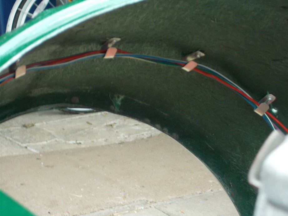
Last job was to tightly cable-tie off the junctions between the various legs of the loom so that, once it's removed, I can bind it accurately. This last photo' shows how the end section runs inside the top of the nose. The tails of the P clips won't be bent right up until final loom installation.


That was it for the day.

Regards, Mick
11 Oct 2017, 8:40am Mechanical Overhaul Electrics Interior & Trim
Double Trouble

Yesterday, as planned, I began binding the front section of the loom with self-amalgamating tape. By the time I'd worked my way back to the alternator/oil and water gauges/distributor junction a doubt had crept into my mind. Haven't I forgotten something? It was the lack of a cable drive connection on the distributor that had triggered it - I hadn't made provision for electronic tachometer wiring. A rummage through the snakes' nest of my spare wires boxes revealed every colour under the sun, bar the white and white with a black twist that are required to maintain my slavish adherence to wiring conventions. I ordered the necessary on Ebay (5 metres of each!) and the nice man has just delivered it :).

As I'd suspended that job I'd decided to have a closer look at the MGF pedal box. It has three M8 tapped mounting holes in its vertical face, perfect for mounting it. The bulkhead in the footwell is too far forward for human legs to reach (Clyde would manage) so I thought I'd attach the box to a temporary wood structure that I could slide back and forth to accurately determine final positioning. On offering up the box to a piece of scrap 13mm ply I saw that the mounting points were misaligned: the donor must have been in a frontal collision. No wonder it was so cheap! I'll stick with the MGF solution despite this setback, but hope one turns up in my local scrapper.

Slightly disillusioned I called it a day. I'm now off down to the cave with my new wire to perform some more binding.

Regards, Mick
17 Oct 2017, 5:39pm Engine Chassis and Body Electrics Interior & Trim
Plodding On

Thanks for the encouragement Paul. As my mother used to often say: "It's no fun if it's easy".

I've not had a lot of project time in the last week, but yesterday and today I managed a good few hours in the respectively windy and sunny cave.

My first job was to continue nibbling away at the coaming moulding to provide clearance for the clocks, switches and warning lights. It took about half a dozen revisits before I was happy that the minimum damage commensurate with a sound fit had been done. Surprisingly, despite the amount of GRP removed, the centre section was still very rigid, unlike the 'wings' which are rather floppy.


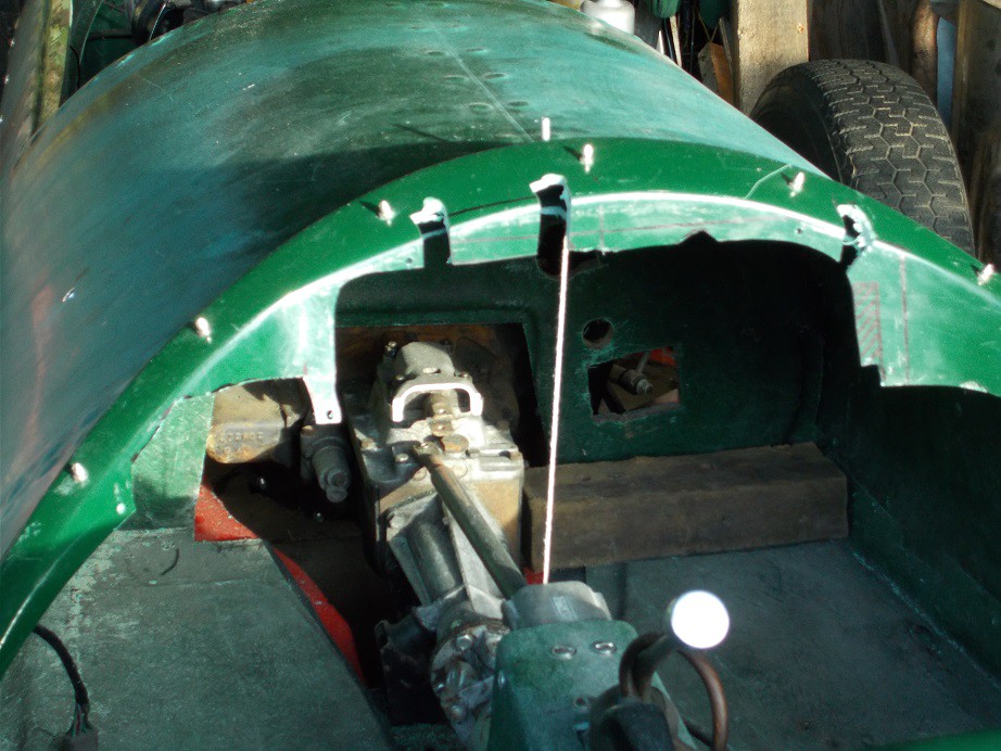
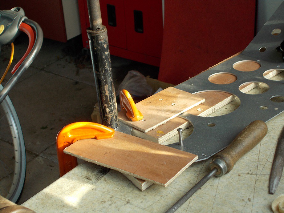
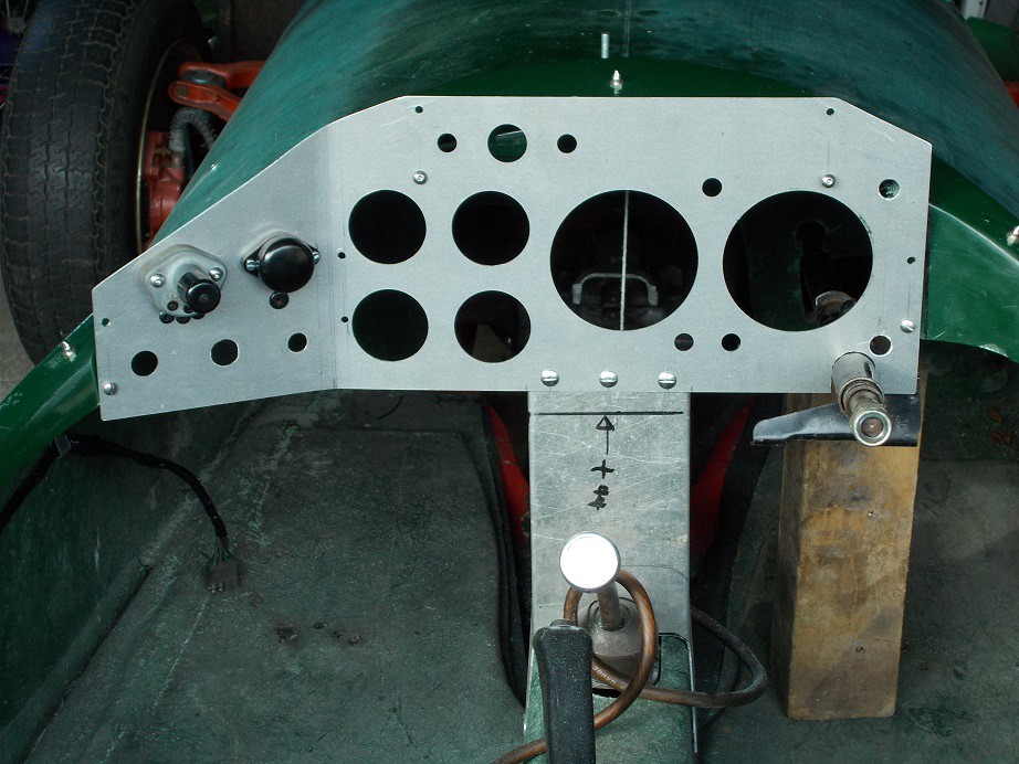
The next job was to detach the loom, clocks and switches from the dash to facilitate cutting the notch for the steering column. I stowed it away in a stacking tub to await the distant day when it's re-installed in anger. I clamped the dash to the bench and drilled a semi circle of 4mm holes around my paper dot. I joined these to the bottom edge with two hacksaw cuts, removed the scrap and cleaned up the curved portion with a half-round file, use of the rat tail proving unnecessary. To my amazement, I'd measured so accurately (more luck than judgement!) that, on offering it up, the steering column was suspended in its new home. Result!


I fitted the dash to the body and the upper column to the lower section with a block of wood to keep it straight. It all lined up perfectly, another result!

I then put the scuttle brace in position usung my tri-square to ensure correct alignment. I marked its position on the dash, removed same, clamped it to the bench again, and marked and drilled three 5mm holes. Replacing the dash I marked and drilled (on the bench) matching holes in the top of the scuttle brace. Amazingly (again!) they lined up perfectly so I loosely bolted them together.


Not wanting to push my luck (quit while you're ahead!) I called it a day and packed up, well satisfied with my efforts.

Regards, Mick
24 Oct 2017, 6:34am Engine Mechanical Overhaul Chassis and Body Interior & Trim
Steering Column Brace

Yesterday, after a few days off, I pitched in with locating the top end of the steering column. I'd purchased a 500mm length of 37x37x3mm angle in ally in anticipation of this job, and offered it up to the bracket on the column, clamping it in position with mole grips. Making sure that it was parallel with the bottom of the dash, I marked the end which would mate with the body with its profile in both planes. I used a pencil taped to a small block of wood to bridge the gap and hacksawed off the scrap.
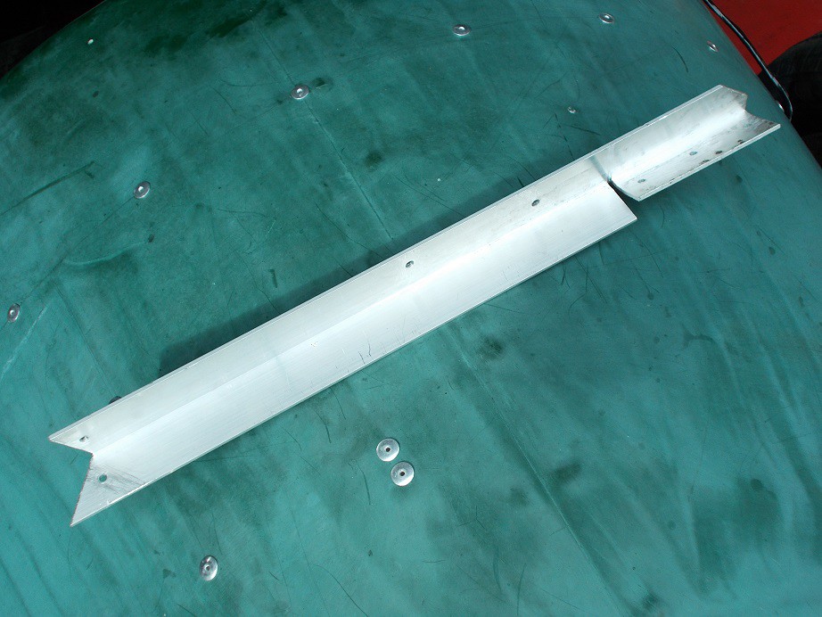


With the angle mole-gripped in position, its newly cut end snugly against the inside of the body, I marked through the two holes in the column bracket, removed the angle, drilled 6mm holes and bolted it back.

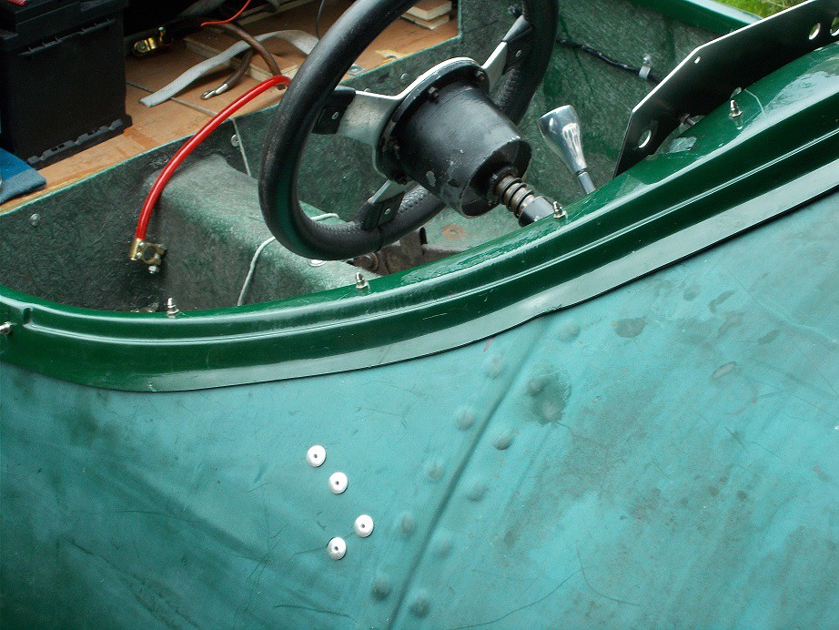
I then made two locating angle brackets, firstly with card, then some of the ally strip I'd used to locate the petrol tank, to fix the RH free end to the body. I clamped these one at a time to the angle, again with the mini mole grips, and marked where to drill it for M5 bolts. After rivetting and bolting it in position with the column still supported by the wood block, I turned my attention to the scuttle brace end.


First job here was to cut a suitable slot in the angle and bend back the side which would mate with the brace. It took a few goes before I was happy with it.

I then cut a small slot in the return on the brace to accommodate the front edge of the unbent end of the angle. With everything sitting nicely I could then mark and drill the 5mm holes to bolt the two together. I removed the wood block and made a realistic attempt at moving the new attachments - they were solid as rock. The only blot was that where the column comes through the slot in the dash, a gap of about 2mm had been overlooked somewhere in the proceedings :rolleyes:. I can easily rectify this with a similar thickness ally spacer between the brace and the column. The ugly protruding end of the angle will be much less obtrusive once it's been painted matt black, the eyes of interested parties hopefully being drawn to the dash.
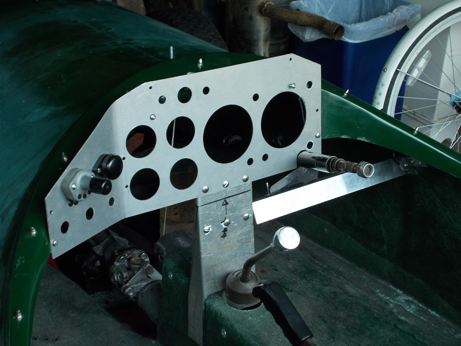


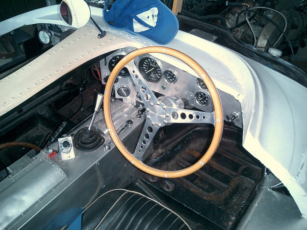
I dug out the steering wheel which came with the project, popped it on, and wormed into the cockpit. The wheel's boss is very deep, locating it far too close, so a replacement will have to be found. I made a few brmming noises, extricated myself and packed everything away, having once again decided to quit whilst ahead :). Apologies for the pictures having been taken out of sequence, and for the crap one of the body brackets. This last picture shows both the depth of the boss and the heads of the rivets attaching the aforementioned angle brackets.


Regards, Mick
25 Oct 2017, 4:39am Engine Chassis and Body Electrics
A Short Day

I'm not sure quite how to finish the edges. They're not sharp as I'd gently profiled them with a fine file. I think maybe I'll use some small section transparent split edging strip which would be quite unobtrusive.

Yesterday I had hoped to make a start on fitting my stainless steel exhaust, kindly delivered last week by Spitfire Steve. I don't have any of the mounting gubbins so some Ebaying or breaker's yarding would have been involved. However, as it was drizzling and I wanted to plonk the body on the grass to access the chassis, this had to be postponed. Maybe today as the forecast is good?

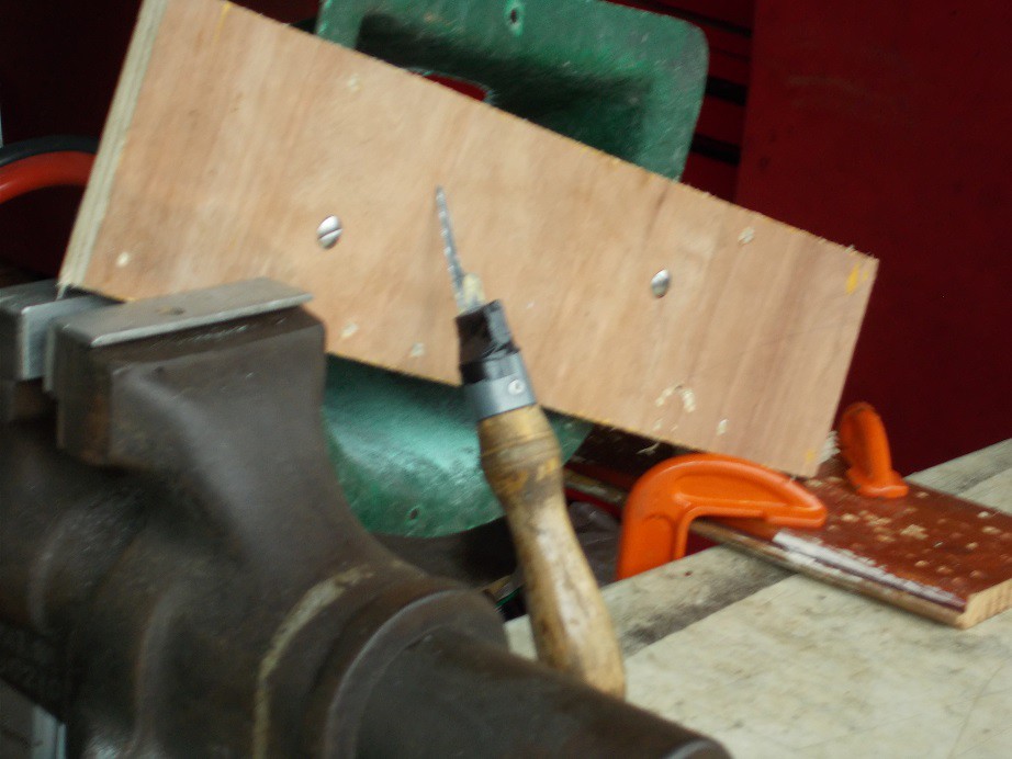
A job I've been putting off is cutting the headlamp holes in the GRP mounting pods, so I decided to tackle that. The first hurdle was how to fix the pod securely to the bench? I drilled matching holes in one of my many ply off-cuts and bolted the pod to it with big washers to spread the load on the GRP. I clamped it in the vice with its free end supported on a piece of scrap wood G-cramped to the bench - it was suitably rigid. Apologies again for crap photo'.


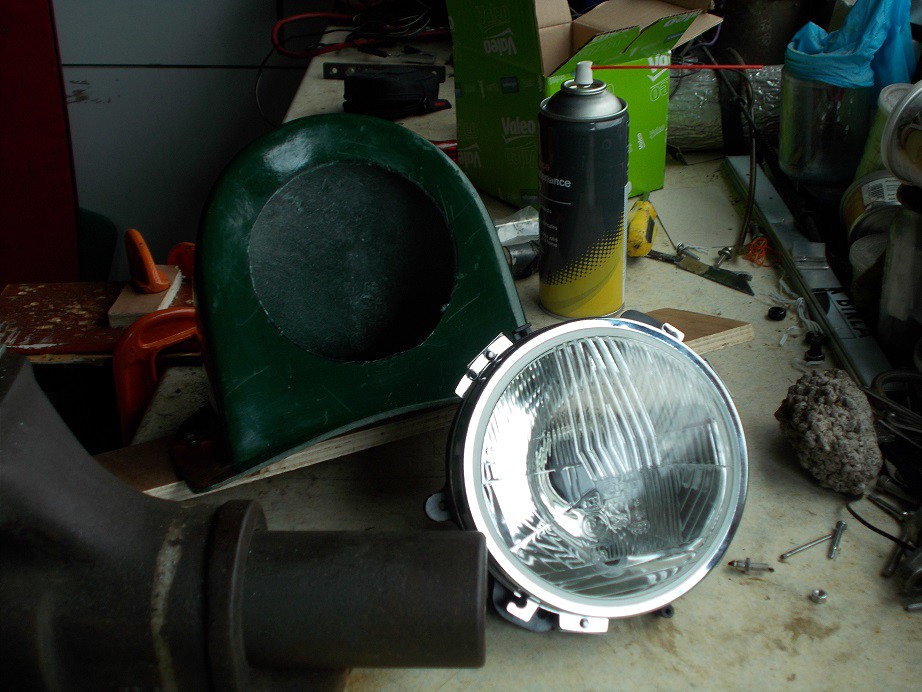
Next problem was what to cut it with? I considered the 'ring of holes' method but discarded that idea because of the amount of filing needed to clean the edges. My solution was to make a super fine padsaw blade by disc cutting a short length of hacksaw blade to size. I drilled three starter holes 120° apart in the marked face of the pod and set to with my new tool. It must have taken a good hour of patient work but I was delighted with the result. I assembled one of my 5¾" headlights and offered it up. It slotted into its new home perfectly, all that was now needed were the holes for the mounting and adjustment screws. My ex-neighbour turned up at this juncture for a coffee and a chin wag and, after he'd gone, being full of cold, I called it a day.


Regards, Mick

November 2017

9 Nov 2017, 6:52am Interior & Trim
Dash Saga

The alli from which my dash is cut was supplied by a friend who has a workshop. I sent him my own blank with the centres of all the holes marked with a punch with a list of the required diameters. Top bloke that he is, he cut it from a new 3mm blank of unknown (to me) grade. £27 all in!

I had considered doing it all myself, but the problems I'd encountered with my A352 dash (also 3mm unknown grade), especially the mammoth fag of cutting the two 4" holes, made up my mind.


Picture courtesy of Scottie22 :)

At 3mm thick both dashboards are nice and rigid, especially once the clocks are fitted. As long as the fixings to the body are sound (and I'm a big fan of scuttle braces!) 3mm of any reasonably stiff grade will do the job.

Regards, Mick
23 Nov 2017, 8:08am Engine
Progress? Not a Lot

I haven't been down the cave much for the best part of a month now, a combination of weather, health and lack of motivation.

Yesterday morning my daily 'Kit Car' search on Ebay brought up this. Lightweight frame and body with one of those bewilderingly popular overweight and huge truck engines doesn't strike me as very good combination. Be interesting to see if anyone's daft enough to shell out two and a half grand for it, especially as it'll need IVA. No mate, just clap the Cortina plates on, you'll be OK :rolleyes:

Regards, Mick
25 Nov 2017, 6:25am Engine Mechanical Overhaul Chassis and Body Electrics
What a Joker!

I belong to the Moss Owners' Facebook Group: the following post appeared on my feed. Says it all, except 'Caveat Emptor' should maybe have been in red capitals!

[COLOR="GREEN"]'As the original owner of the Yellow Monaco I have to say I laughed when I saw this. I sold the car via eBay to this seller last Saturday for £500 which I was happy to get knowing how difficult it would now be to get it on the road. The advert is (to be diplomatic) riddled with inaccuracies. I ordered it from Moss Cars at Store Street in Sheffield in March 1985 although by the time I collected it in April they had moved to a factory unit on the outskirts of the city. Therefore I owned it 32 years 7 months from April 1985, not 34 years from 1984. Lightweight racing chassis? It has a ladder chassis designed to accept Ford mechanicals and a longer bodyshell than the Spitfire based version so is more likely to be heavier. Lighter and stronger yellow gel coat body? Being longer than the Spitfire version it'll be heavier, nothing special about it other than the colour which was a special order (I believe it to be the only one in that colour). Engine was bog standard out of a 1973 2 litre Cortina, which last ran about 20 years ago and hadn't even been cranked over by hand in the intervening years. No fancy pistons, crank or cam and only ever had a single carb which was still with the car on Saturday. Judging by the photos the engine in it is the one it was sold with a few days ago. For someone who claims to have had 3 Monacos he seemed a little unsure of where the headlamp pods were supposed to go. Make of all this what you will but as ever caveat emptor!'[/COLOR]

Regards, Mick

December 2017

4 Dec 2017, 9:31am Electrics
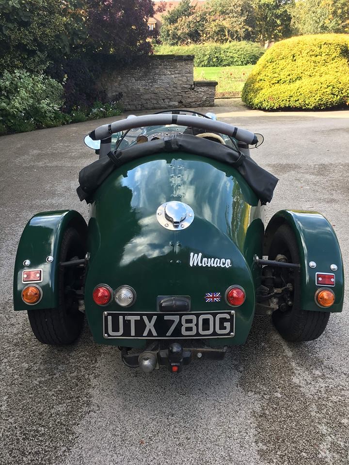
I like my standard 5.75" pods, I think they enhance the overall quirkiness. The builder has used the same stop/tail lamps, reflectors, style of number plate and light as me. A man of impeccable taste :icon_wink:.

All four indicators are too far from the sides to be strictly legal, and the view in that bullet mirror will be more or less useless. A few big [COLOR='RED']722[/COLOR]s wouldn't look too shabby............

I still love it, though!

Regards, Mick)
4 Dec 2017, 2:50pm Chassis and Body Electrics
Progress (sort of) at last.

After six weeks or so of coughing, spluttering, looking at the rain/frost/wind and wondering why my get-up-and-go had got up and gone, I at last ventured down to the cave this morning and pitched in.

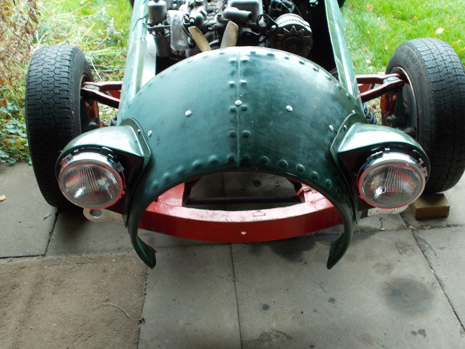
First job was to drill the long awaited headlamp bowl mounting holes in the GRP pods. This involved levelling the car with my spirit level on the front cross member with one side jacked up to get the bubble central, then using a plumb line to find and mark the vertical. I'd already marked the exact tops of the bowls so drilling was a matter of holding them with the marks aligned. I then temporarily mounted them for the picture. The parallax effect makes them look a little pissed but they're spot on.


My ex-neighbour turned up at this juncture for a coffee and a chin wag so it was a couple of hours before I ventured back down to the cave. I decided to fabricate a steady bracket for my reversing spot lamp, as I'm certain it would go seriously AWOL if I relied solely on the bottom mounting. I made it from cardboard and transferred the holes and bends to a spare length of the ally strip I'd used for the fuel tank mounting straps. I then pop-riveted it to the back of the lamp housing and after a couple of small adjustments to the bends, it sat perfectly. The mounting hole in the body will have to wait as access for the inside nuts needs a spare pair of hands, unavailable today.


I included the back of the lens in the shot to show my home-made LED bulb which will ensure minimal load on the lengthy supply cable.

That was it for the day.

Regards, Mick
5 Dec 2017, 7:10am General Update

I stand corrected!

Regards, Mick
14 Dec 2017, 8:23am Chassis and Body
Complete Non-Sequitur

I didn't know where else to put this, which came up on my FB 'Historic Lotus Register Group' feed. It's a Type 14 Elite body on a Spitfire chassis. Full marks to the builder for fitting a Triumph badge!


Regards, Mick

January 2018

15 Jan 2018, 7:08am General Update
Hoping for a Monaco Summer

I really hope to get the Monaco on the road this summer.

Rumours that I have an ulterior motive should be ignored.

Regards, Mick

25 Jan 2018, 8:24am Chassis and Body
Non!

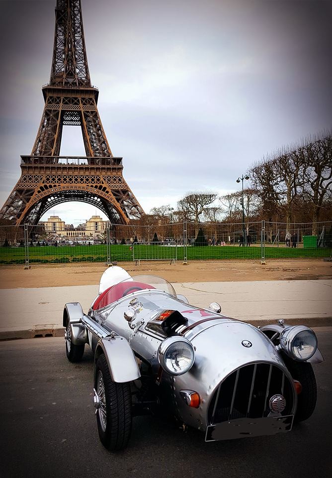
It's gone to France, I believe, where there's a strong Monaco following. My suspicions were aroused by this appearing on my FB Moss Owners' Club feed........

Lucky guy!

31 Jan 2018, 8:41am General Update
And still they come.......

This appeared today.

Regards, Mick

February 2018

24 Feb 2018, 8:14am General Update
And Still They Come.........

€8,500.

Regards, Mick

March 2018

6 Mar 2018, 7:22am General Update
Our Loss. Their Gain

Another Monaco has gone through the tunnel, I learnt from my Moss Owners' Facebook feed this morning. Triumph straight six powered - lucky old Pascal!


It broke down on the way and this good old boy stopped, correctly diagnosed the fault, and rectified it. Entente Cordiale in action!


Regards, Mick
28 Mar 2018, 7:52am General Update
What A Joker!

Rather than scraping his meagre living selling on kit cars, I think he could easily make a fortune as a stand-up comedian...........

Regards, Mick