Rear wing fitting
I have repaired and trial fitted the rear wing that had been previously been bodged. Also filled the many holes previously used to fix it as I wanted to start again. And.... filled the ragged holes where the lights were fixed. I am planning on using some round Lucas style lights rather than the original Marlin supplied Rubolite ones
As I am fitting cycle wings at the front I have also shortened the rear wing removing the stub of the running board where it would have joined to the front wings. Considering the original plan was to fit cycle wings all round it actually looks pretty good. The fit of the wing is not the best though - nothing I have done - that's just how it was made. But by the time I fit some wing piping the gap that appears at the top will disappear (I hope). I could probaly pull the tub and wing together a bit more but I didn't want to over stress 40 year old fibreglass.
On to the other wing now....
 rear_wing_repair
 by
Robin Martin, on Flickr
 rear_wing_fitted1
 by
Robin Martin, on Flickr
 rear_wing_fitted2
 by
Robin Martin, on Flickr
I have almost finished painting the chassis using CraftMaster coach paint. This requires a minimum of 6 coats, 2 x primer, 2 x undercoat and 2 x topcoat hence the long delay since I last posted (Plus I have had Covid). Although it takes ages to do the result is worth it.
I have done the main chassis in black raddle which is a sort of semi gloss. It's tough as old boots once it has had a few weeks to dry.
The bit of the chassis that supports the windscreen frame, and the frame itself is MG Maroon and boy is it shiny. This will match the body colour. The final coat I applied using brushes made by Purdy which cost an arm and a leg but the result is worth it.
 chassis_painted1
 by
Robin Martin, on Flickr
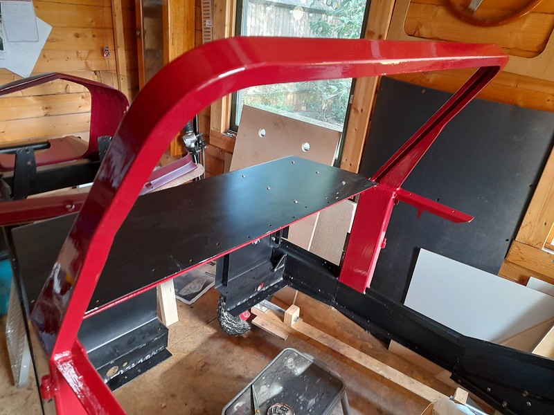 chassis_painted2
 by
Robin Martin, on Flickr
Now all I have to do is paint the rest of the body!
Now the chassis is painted I have permanently fixed the front and rear bulkheads using a combination of stainless screws and mastic.
I have also made a new front grill using some stainless mesh, as the old "crinkly wires" used by Marlin are no longer available. It's a bit of a b*gger to cut but the result is quite pleasing.
 new_grill
 by
Robin Martin, on Flickr
My first attempt at coachpainting some of the fibreglass. it's not bad even if I do say so myself. This was coat number 5 - the first topcoat. 6th coat (2nd topcoat) looked better but forgot to take a picture. Still a long way from perfect but good enough. The red, by the way, is considerably darker in real life.
 coach_painted1
 by
Robin Martin, on Flickr
And now I have started to re-assemble the car in ernest. Near side front suspension is done. The big problem with the Marina is you cannot adjust the castor. Which in turn affects the steering self centering - big time. But at least with my adjustable tie bars you can tweak it. By measuring the angle of the torsion bar relative to the chassis I have established that the castor is bang on the suggested 2.5 degrees. Hooray. Note the Heath Robinson angle device!
 castor_angle
 by
Robin Martin, on Flickr
I don't think any of us that visit here could be called young! I keep telling myself this will be my last build but you never know....
A few more pictures. Having a bit of a push at the moment.
 front suspension complete
 by
Robin Martin, on Flickr
 pedalbox complete
 by
Robin Martin, on Flickr
 painted scuttle top
 by
Robin Martin, on Flickr
I have mocked up the dashboard. I am going for the minamilist look - large Jaguar rev-counter in the centre, standard Smiths fuel and combined oil pressure / temperature for the smaller gauges. Bicycle speedo and oddometer discreetly mounted. No glovebox as the suggested one is uselessly small.
 dash mockup
 by
Robin Martin, on Flickr
Lucas windcreen wiper motor and boxes trial fitted. These are a real b*gger to get right but essential to do so as they are fitted in the clamp which holds the screen in place. As this is sealed in with mastic once the screen is fitted so you don't want to be taking it out very often!
 wiper motor installed
 by
Robin Martin, on Flickr
Front brake pipes all run. I didn't follow the suggested route from the manual. I know that one of them bridges the point where the side mounted exhaust exits the bonnet side panel - but I am not going to be doing that with the exhaust anyway. I had to make the brackets for the front flexi pipes as my (very early) chassis was missing them. The flexis are a bit tight but I think they will be OK once the suspension is at its working height.
 front brake pipes
 by
Robin Martin, on Flickr
 front brake pipe bracket
 by
Robin Martin, on Flickr
A litle bit of progress, probably the last for a while as my wife has just this week had a hip replacement and apparently being nurse and chief cook and bottlewasher is now more important lol.
I made a backing plate for the dashboard to take the three instruments I am using. The centre place is a giant rev counter from a Jag. Left and right of it will be a fuel gauge and combined oil pressire / water temperature gauge. The plan is to make the actual dash from aluminium recycled from the old bonnet sides which I will be remaking.
 dashboard1
 by
Robin Martin, on Flickr
In the lower part of the picture you can see the start of my new gearbox support. Originally the gearbox was suspended from the transmission tunnel - an arrangement I didn't particulary like.
That's all for now...
I managed to find a few odd half hours in between being Florence Nightingale and Jamie Oliver :-)
I have completed the new gearbox mount which will also support the transmission tunnel and hence floor. It also means I can make the transmission tunnel sides in two parts that will fit in my bender.
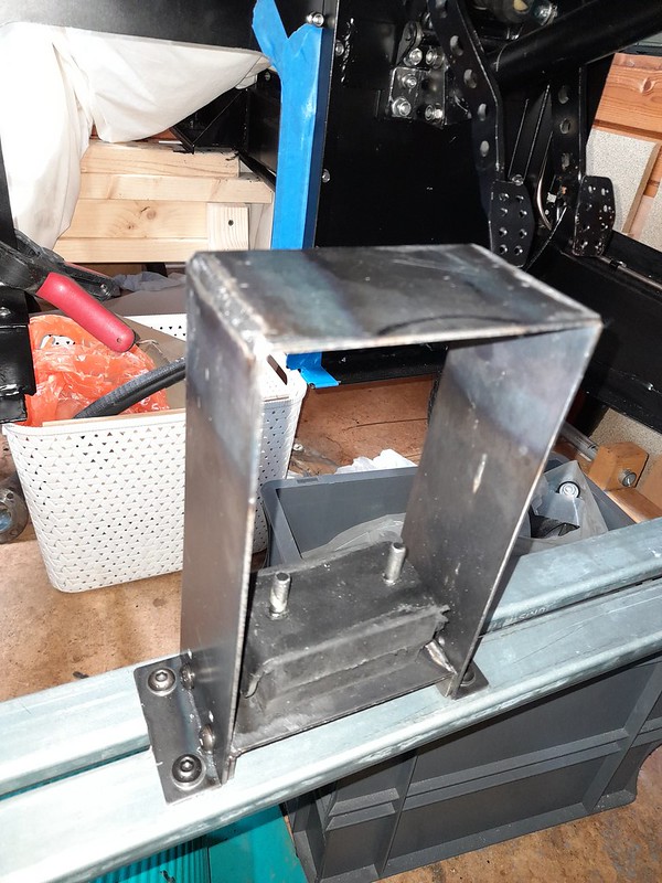 gearbox_mount
 by
Robin Martin, on Flickr
And I also made up and mounted the fuse/relay box which will also act as a distribution point for the electrics hopefully avoiding the spaghetti look. I used a similar arrangement in the Pembleton.
 fuse_box1
 by
Robin Martin, on Flickr
And on the engine side two mate'n'lock connectors to avoid cables having to go through the bulkhead.
 fuse_box2
 by
Robin Martin, on Flickr
The battery box may or may not be fitted below the fusebox. Undecided atm.
I have completed the transmission tunnel. Pleased with the result but folding the long lengths of sheet steel almost destroyed my home made bender. Steel is so much tougher than ally. Hopefully I wont need to do it again.
Getting a good fit at the bulkhead end proved tricky as the tunnel is not square to the bulkhead and the chassis that supports the torsion bars is also at a slight angle. But got there is the end after a lot of bad words....
The observant may notice that I used a stretcher / shrinker to acheive the flare in the tunnel at the diff end, and again at the gearbox end. You can still see the grip marks on the flange.
 transmission tunnel 2
 by
Robin Martin, on Flickr
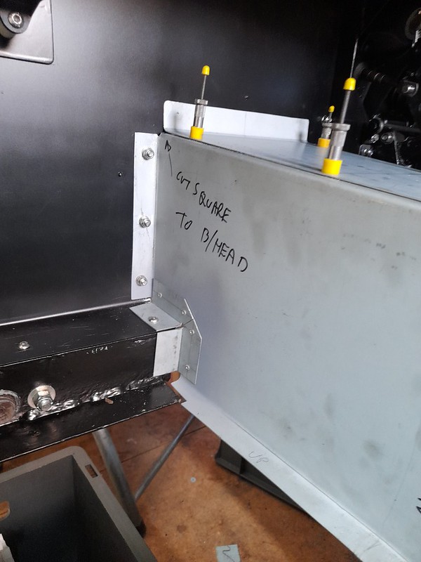 transmission tunnel 3
 by
Robin Martin, on Flickr
Next job - handbrake. I have purchased one of Richard Oakes trigger handbrakes and a lovely piece of kit it is too...
I have a handbrake! And it works :-)
 handbrake 1
 by
Robin Martin, on Flickr
I have to say that the trigger handbrakes are beautifully made and, as a bonus, you get to deal directly with the famous Richard Oakes.
The handbrake cable from the Marina is the first I have ever seen with a built in grease nipple. You can just about see it on the centre right of the picture.
 handbrake2
 by
Robin Martin, on Flickr
I have taken the opportunity of the last few mild days to complete the fusebox and battery box. The 3 connectors you can see are for the dashboard and rear loom. 2 other connectors appear the other side of the bulkhead, 1 for the engine and the other for the front lights etc. I have used industrial mate'n'lock connectors mainly as I had a load left over from the Pembleton build.
The ignition switch I have chosen is a fancy, key operated, industrial job but only has a low switching capability hence the large relay.
And of course the inevitable isolation switch.
For safety, as the battery in in the footwell rather than being under the bonnet, I have fitted two large fuses to the battery box, 1 for the starter (125 Amps) and the other for everything else (40 Amps).
Just need the actual battery now!
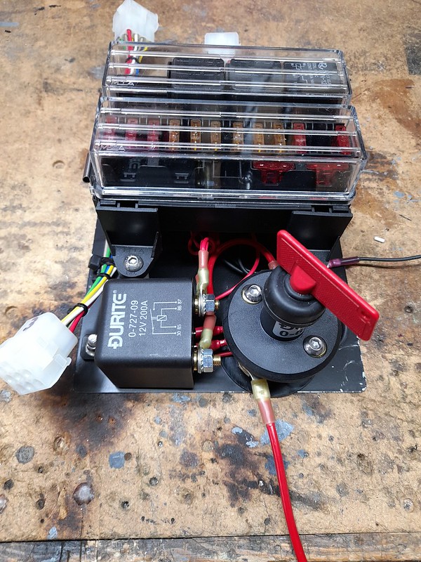 fusebox
 by
Robin Martin, on Flickr
 fusebox_mounted
 by
Robin Martin, on Flickr
Next step will be the dashboard....
Today I completed construction of the dashboard blank. I made it from one of the bonnet side panels which I am replacing as they are full of holes in the wrong places. And I thought it would be cool to incorporate at least some of the old panelwork! As it is over 40 years old it comes with a pre-patinated finish which I think I might leave.
Difficult to see from the picture but I formed a radius on the lower edge using a mould and a small rubber hammer. And there is a 20x20mm re-inforcing angle running the entire width at the top.
The plan was to use some s/h Smiths gauges but as they are almost as expensive s/h as new nowadays so I think I will buy some new ones. Just water temp and fuel level are all I intend to use.
Now comes a question for anyone who still looks at this forum. I have several toggle switches to mount on the left in the blank area, and several indicator lights to mount on the right in front of the steering wheel. Should they be in a horizontal line, or should they follow the line of the scuttle top and slope upwards? Hmmm...
 dashboard2
 by
Robin Martin, on Flickr
As suggested I have made everything line up with the scuttle top. I am still not convinced though ;-)
 dashboard3
 by
Robin Martin, on Flickr
The little rectangle of masking tape immediately in front of the steering wheel represents the tiny digital (bicycle) speedo I am using. Not very "classic" but practical and cheap! And removable.
I have been trying not to buy any parts with the classic car label as it seems to add a premium to the cost. But the Lucas trafficator switch you can see is perfect for the job. I can operate it without removing my hands from the steering wheel as per the IVA rules and - well - it looks the part. I don't need an IVA as the car is already registered, but I consider the rules to be a good guidline where practical.
I have been pondering the problem of my propshaft for some time now. For some reason the little screwed cap that holds the oil seal on the splined joint is way to big and hence impossible to screw up. I can only think that it has come loose at some point and years of rattling arround on the propshaft joint has stretched it. Its at least 3mm too big in diameter.
 propshaft_problem
 by
Robin Martin, on Flickr
Anyway I was doing some routine maintenance on the Pembleton. The driveshafts (2cv) have 3 joints the centre one of which is a sliding spline like on a propshaft. They are all protected by rubber gaitors. So I got out the callipers and, would you believe it, the size of the shafts making up the splined joint is almost the same as that on the Marlin propshaft. Getting excited now... So I ordered a gaitor from ECAS, the main source for 2CV spares and it fits perfectly!
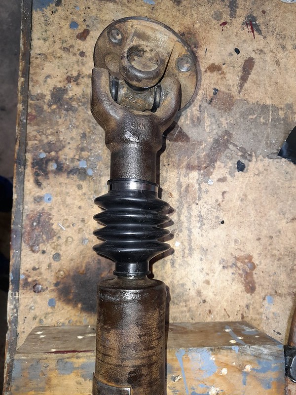 propshaft_solution
 by
Robin Martin, on Flickr
Not very often you get a piece of luck like that.
I thought it was about time to do a reality check and make sure the gearbox actually fitted in my new transmission tunnel. I had to take the hacksaw to one of the unused lugs on the gearbox casing but now it fits with about 1/2" clearance on either side which hope is enough for any movement. And the propshaft fits as well, always a bonus....
 gearbox_fit1
 by
Robin Martin, on Flickr
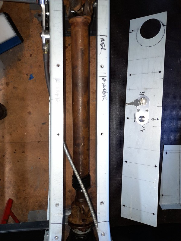 propshaft_check1
 by
Robin Martin, on Flickr
From the front it looks like I may have to adjust the position of the fuel line but I'll wait untill the gearbox is finally fitted before I do that.
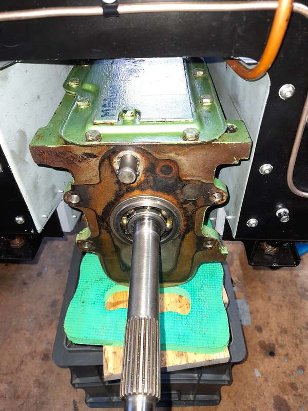 gearbox_fit2
 by
Robin Martin, on Flickr
And I have taken the advice of various sages and fixed the tunnel top using M5 screws and rivet nuts. I have put the ignition switch on the top of the tunnel, the idea being all of the wiring is then almost impossible to get at for any would be joy rider. The switch itself is an industrial tamper proof item. NOS from ebay for a bargain tenner.
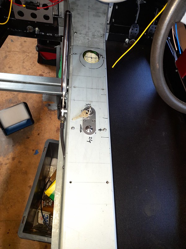 transmission_tunnel
 by
Robin Martin, on Flickr
And yes the gearbox is almost new! It looks like it had been recently fitted before I bought the car from the previous owner and builder.
I have just about completed the wiring loom now. All I need is the engine and a few lights to connect up!
I have confined a lot of the spaggetti to the dashboard.
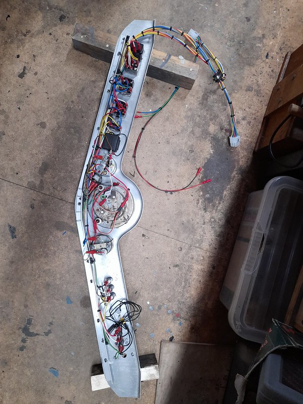 dashboard5
 by
Robin Martin, on Flickr
The little button (temporarily) mounted on the steering wheel is actually a wireless horn button. The receiver is amongst the stuff on the rear of the dashboard. The plan is to bodge it around so that it sits behind the steering wheel central horn push.
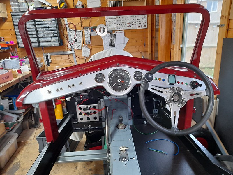 dashboard4
 by
Robin Martin, on Flickr
And a few more pictures of the rest of the wiring waiting to be connected up. All i need is the engine now!
 loom2
loom2 by
Robin Martin, on Flickr
I have managed to keep the high current (starter motor) wiring nice and short. Not sure what route I am going to use yet to reach the rear of the car but it is all contained within one cable.
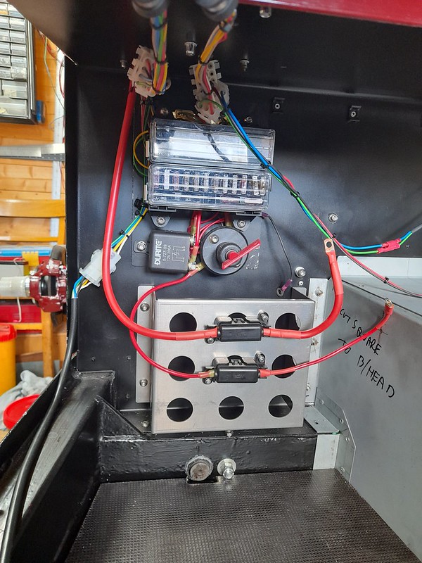 loom3
loom3 by
Robin Martin, on Flickr
I have been working on the heater install the last few weeks. I bought a (fairly expensive) heater from T7Design as the basis. I don't think it represented good value for money! When i took it to bits to modify slightly I found it just comprised a computer style fan, albeit a powerful one, and a heater matrix in a simple aly box. It would have been considerably cheaper to make it myself. Ho hum - you live and learn.
The heater has 4 outlets, I used 2 for the demister vents and the others for the footwells. I added a 5th, with a little flappy outlet thingy, that points directly into the interior. The heater is supposed to be 3.5kw (hmmm) so I hope it will keep things toasty.
I replaced the heater front panel with one of my one which also serves to mount it and carries the on off switch, the above mentioned 5th vent and will also act as a mount for a 12 volt socket and the choke cable.
At the moment the heater is just configured for re-circulation, but I have allowed enough space behind it to allow for some ducting to the outside world should it prove necessary. For the moment I considered this a complication too far.
I recently discovered the Car Builder Solutions catalog and this has provided the heater hoses with right angle bends. Very handy.
 heater1
 by
Robin Martin, on Flickr
 heater2
 by
Robin Martin, on Flickr
 heater3
 by
Robin Martin, on Flickr
As a prelude to making the bonnet side panels I have been playing with ideas to mount the spare wheel. The intention is to side mount it on the passenger side as the car will mainly be driven with just the driver and this will help to balance out the weight a bit. I purchased a rather agricutural looking trailer spare wheel mount from Amazon to use as a starting point. It now looks like this.
 spare_wheel_1
 by
Robin Martin, on Flickr
And (temporarily) mounted on the chassis rail.
 spare_wheel_2
 by
Robin Martin, on Flickr
 spare_wheel_3
 by
Robin Martin, on Flickr
I have yet to decide on the final position as the exhaust will also exit on this side. But clamping it to the chassis showed is was good and sturdy - if still a bit agricultural lol.
I have also test mounted the radiator. I acquired a new old stock rad from another Marlin owner. It's from a Vauxhall Chevette (Viva?) I understand. Originally the car had a heavier duty looking rad from a Morris 1800. On comparison it has more fins but doesn't have any more waterways than the Vauxhall rad so I hope the Vauxhall rad is going to be OK. It will be getting as big an electric fan as I can fit in. The original design hangs the rad on some brackets from the join between the bonnet sides and cowl. Or in the case of this car just wedged between the chassis rails.... This means that taking the bonnet sides off for any reason in the future will be a real pain. so I have made a couple of L brackets to mount it directly to tha chassis. Seems to be a better solution although it does mean drilling the chassis for some rivet nuts.
 radiator_new_old
 by
Robin Martin, on Flickr
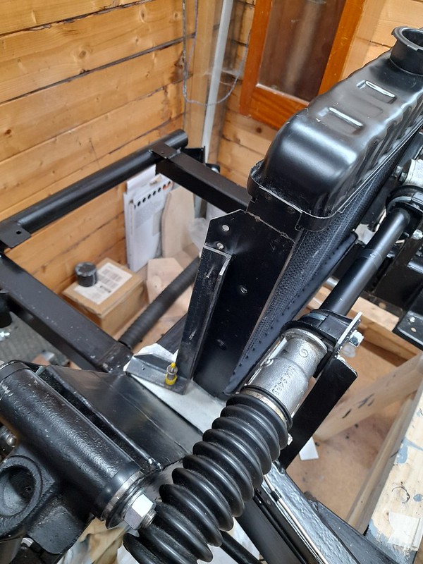 radiator_1
 by
Robin Martin, on Flickr
 radiator_2
 by
Robin Martin, on Flickr
That's all for now. Bonnet sides next!
I have made the first of the two bonnet sides. A lot of carefull measuring involved as it is a big panel and didn't want to cock it up. The front and back edges are parallel but top and bottom are both set at an angle. the bottom to follow the chassis and the top to giving the bonnet a pleasing drop towards the front. The original panels were shot but useful as a double check.
The original bonnet side has a lot of folds at the edges not really necessary for strength. But it's actually a clever part of the design - the folded edges are what you actually see which means the 'orrible cut edges are hidden. Which is just as well as the originals seem to have been cut out with a jigsaw with the edges left rough. All done for speed of course. Anyway I made the replacement exactly the same way (I did clean up the edges), the only difference being I riveted the ally angle that strengthens the top rather than nut and bolting it in place as per the original.
It would be an understatement to say I am pleased with the result :-)
Just the other side and the bonnet tops now...
 bonnet_side_making
 by
Robin Martin, on Flickr
 bonnet_side_1
 by
Robin Martin, on Flickr
 bonnet_side_2
 by
Robin Martin, on Flickr
I have completed the other bonnet side. Took less than half the time of the first one!
The bad news though is that I trial fitted the old bonnet which I was going to use as a template to make the new one. It is an awful fit - in fact it doesn't really fit at all. So I am going to have to fettle that first before I can even consider using it as a template. Hmm
 bonnet_side_3
 by
Robin Martin, on Flickr
As a bit of an asside I have been doing some planning. I am considering using this steering wheel. It's an old Triumph (Herald?) steering wheel and is dished and has sprung spokes the idea being it does provide some protection in the event of a prang. What do people think?
 alternative_steering_wheel
 by
Robin Martin, on Flickr
And I have been thinking about the exhaust route. I was always going to have a side mounted silencer but I would like the actual output to be at the rear of the car - not by the passengers ear. It looks like I should be able to route it between the chassis and the rear nearside wheel. Again - what do people think?
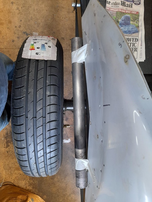 exhaust_1
 by
Robin Martin, on Flickr