MadaboutKitcars

Build Stories are assembled automatically from a build thread's own author, in their own words and order — see all featured builds.

Mick O'Malley's Moss Monaco

By Mick O'Malley · 282 updates · Jan 2017 to Nov 2023

Read the full original thread (with everyone's replies) in the archive →

June 2017

8 Jun 2017, 5:59am Mechanical Overhaul Chassis and Body Interior & Trim
One Small Step.........

After a few days of rain watching, yesterday I took advantage of the fine weather to address the last couple of hurdles before final fixing of the body to the chassis.

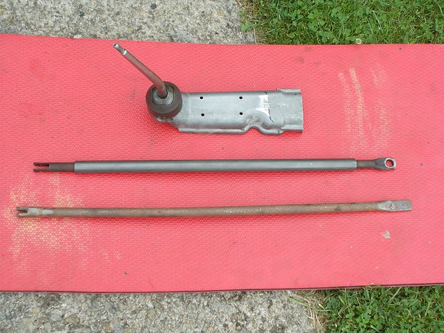
As the seating position in the Monaco is well aft of the Spitfire's, the gear lever needs to be similarly relocated. I'd done this on the A352 to get an authentic D Type forward angle and situation. I did this by butchering two extensions and joining them by bolting through a length of aluminium channel. The rod was extended with a length of welded on close fitting tube. This has worked well in service.


However, the build CD I got with the kit (scans of the 'manual', I don't think CDs were invented when it was manufactured) describes a simpler solution - chop the extension and bolt the driver's end through the GRP tunnel. Amongst the box of brackets I got is a fabricated extended rod but it's pretty crude so I'll extend the original again.


Next job was to fabricate brackets to firmly locate the body sides to the front outriggers. I couldn't use the existing tappings in them as the off side one has gone AWOL. I decided to make them from steel rather than aluminium sheet as decent strength and rigidity is needed. I plumped for M6 bolts through the top face of the outriggers and a combination of M5 bolts and big head rivets through the body, the outward curve of which means that neither of my rivet guns would fit to rivet the lower holes

Cardboard assistance was again used to make templates for the brackets and the angle of bend required. Due to the asymmetry of the body one of the nearside fixing holes had to be tapped into the inner boxed in section of the near-side outrigger.


I next applied the foam cushioning to the manufacturer's rear suspension bridge body mounting points and offered up the Monaco body. It now sits flush along its whole length and to my fabricated boot floor, and the mounting holes for my outrigger brackets look perfectly positioned.


I then quit while I was ahead, a sound decision as it began to rain whilst I was packing everything away!

Regards, Mick
24 Jun 2017, 5:33pm General Update
Whilst searching for a photo' of my laps of Castle Combe in a 550 Spyder, I at last came across one of my friend's Phaeton in M'boro McClaren colours. I'm the gormo on the right, blinking at exactly the wrong moment, and my kit car pal of 35 years on the left gives away the era with his mullet!

Happy Days


I also found a forgotten Monaco picture taken at Stoneleigh in 20**?


Regards, Mick

July 2017

16 Jul 2017, 4:41pm Mechanical Overhaul Chassis and Body Electrics Interior & Trim
38 Days Later!

Can't believe it's that long since I posted an update! I haven't been entirely idle, but it's true what they say about ever having found the time to go out to work! Crazy as it seems, on many of the intervening days it was simply too hot to work outside, either in the sun or the stifling heat of the south facing man cave.

I must have had the body on and off the chassis a good dozen times all told trying to ensure that it both sits properly along its whole length and that the holes I drilled aligned perfectly with tappings in the frame. The body now has 12 attachment points: two to the rear suspension bridge tappings; two to the rearmost original body mount tappings; two to the inboard seat belt tappings (these are no good for belts due to the Monaco's revised seating position); two which I described in an earlier posting to the short angled outriggers; and four fabricated angle brackets bolted/riveted to fix the floppy body to the front outriggers and curved front rail.

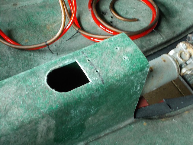
My extended gear change rod is slightly shorter than the pretty crude one supplied which would have put the lever in too rearward a position and pushed the handbrake lever back as well. When I drilled the four mounting holes in the rear half of the casting, I clamped a piece of 6mm ply to it to use as a template for the mounting holes in the tunnel. This worked a treat and the holes align perfectly.

DSCN0256 by Mick O'Malley, on Flickr

DSCN0255 by Mick O'Malley, on Flickr

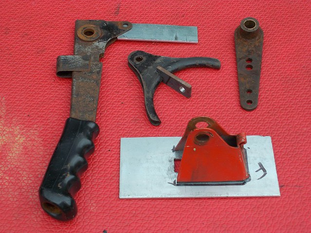
Next job was the handbrake. On the donor system there is a secondary horizontal lever which multiplies the effort. It's too long to fit in the Monaco's tunnel so I decided to use it in the vertical plane. To achieve this I've had to butcher a spare cable guide to take two clevis attachments at 90° to each other. I'll cut the redundant 'wings' off once it's welded. Also, with the lever sitting much higher than on the Spitfire, I'm having to extend it downwards to provide a lower cable attachment hole. Quite how I'm going to mount the pivot rod for the multiplier lever within the skinny tunnel will be tricky, to say the least, but then it's no fun if it's easy.

DSCN0257 by Mick O'Malley, on Flickr

I cable tied my two lengths of thick battery cable together and cut and drilled seven P clips from ally which will locate them within the tunnel and gearbox cover, my battery being behind the passenger side seat back. I'll rivet them in place when the body comes off for, hopefully, the last time.

Today I dug out the ex-MOD seat belts (I've seen some on another thread on here) which I was going to use on the A352 but they just didn't look right. I offered them up and decided where the mountings would be. I then bought the necessary six eyelet bolts and spreader plates with nuts welded on that I'll need.

Regards, Mick
16 Jul 2017, 5:04pm General Update

I can't find a screen like that one, must be doing something wrong?

Regards, Mick

Nope, nothing like that available. Bizarre!
16 Jul 2017, 5:19pm General Update

I've found the hoops they need me to jump through, at last. Pictures now in original post.

Many thanks!

Regards, Mick

September 2017

11 Sep 2017, 7:21am Engine Mechanical Overhaul Chassis and Body Electrics
Not a lot............


Not a huge deal of progress made over the summer months. There was a long wait for my latest batch of welding jobs to be done by my contact of almost 40 years as he has had staffing problems at a very busy time: his real work takes precedence! I've been driving the A352 'D' quite a bit and have had a holiday so the months seem to have flown by.

Anyway, at last my extended gear change remote, hand brake lever mounting plate and multiplier lever mounting bracket are ready for installation. I've now realised that final bolting of the body to the chassis will be almost the last job of all as being able to pop it off facilitates so many of the building tasks.

I've run the battery cables from the 'boot', through the transmission tunnel, to the starter solenoid and cranking motor mounting bolt respectively, with an isolation switch in the +ve. Working out how to crimp the terminal eyes caused a bit of head scratching until I hit on using my water pump pliers with inch box over the arms to multiply the effort. This worked a treat :).

Careful measuring of the limited space for the handbrake effort multiplier lever showed that it could be used, slightly modified, as the manufacturer intended, rather than by my previous idea. The problem of shortening the primary cable was overcome by substituting a length of angle cut from some scrap box section. I've angled the mounting hole in the top of the tunnel to align said rod with the business end of the multiplier lever. As soon as a dry day comes I'll bolt the handbrake bits and gear lever in position with the body off. End of part one.
11 Sep 2017, 8:29am Engine Chassis and Body Electrics
Not a lot, part two...............

This weekend I dug out the loom which I'd carefully wound into sections secured with cable ties. Offering it up to the body revealed two problems 1) The front section for the lights and indicators is missing. This isn't a great problem as 'Spitfire Steve' can bring me one when he drops off my stainless steel exhaust on his next foray up the M5. 2) The rear lights and indicators, being wing mounted, will need their cables routed along the wing stays. Offering up the brackets supplied revealed that, not only are they substantially over-engineered for the lightweight GRP wings, but they're designed for bolting to some other style of chassis frame. Scratchbuilding will be required!

Here are a few pictures of the various bits and pieces mentioned above.


I'll need to create an access panel to fold up the P clips holding the earth lead once the body is mounted.


Regards, Mick
13 Sep 2017, 6:58am Mechanical Overhaul Chassis and Body Electrics Interior & Trim
More Body Mounts and Wiring

On Monday I decided to finish off the body mounting hardware. This involved visiting my local fixings supplier where their warehouseman supplied the imperial screws I needed. He's dug me out umpteen times over the years, never failing to have in stock the obscure threads and lengths I've requested. :)

I had considered using large flat washers to spread the load on the inside of the body, but decided to cut some bigger spreader plates. Under the seating area there are two long ones to be bolted through to two manufacturer's body mounting tappings and two redundant seat belt tappings, the Monaco seats being well aft of the Spitfire position. The picture below shows the 12 mountings: the front four attach the floppy front body; the next two through the angled outriggers; then the inboard seat belt tappings; then the aforementioned original body mounting tappings; the last two into the rear suspension bridge. Once these are all finally in place I don't think the body will be detaching itself in a hurry!


I next turned my attention to the rear loom. As the layout of the various electrical components is significantly different from the Spitfire I decided to re-manufacture it. I've done this on previous projects: my Lomax 224 two years ago being the last. I really enjoy wiring, especially binding my creation with self-amalgamating tape before fitting. The part I don't like is removing the manufacturer's sticky tape underneath. It's just so messy. Once I'd separated the wires I gave each a wipe with acetone so they're now ready to be cut to length; bound together; and fitted with their connectors. I bought a spotlight as a reversing lamp (it hasn't arrived yet - picture will follow) - the loom has provision for this.


To make sure the wiring doesn't come up short I drilled the rear wings for the lights and indicators, balanced them in position and carefully measured the loom runs. I first had the indicators below the lights but transposed them as I thought they looked better that way around.

This last picture is of the modified radius arm mountings which will bolt through the floor. I doubt this will be strong enough so some sort of anchoring strap to the angled outriggers will be needed.


Regards, Mick
13 Sep 2017, 3:53pm Engine Electrics
Earths and Battery

Today I concentrated (between showers) on the battery area of the 'boot'. In my box of electrical bits and pieces I found a terminal block for earthing? The screws for clamping the wires were the right size for mounting three double ended 6mm spades (from Volks Spares) to the block, the fourth clamps being used as intended to secure a spare length of 6mm diameter cable. To the other end of this I crimped an 8mm eyelet connector which will go behind the battery earth clamp pinch bolt. Once it's bolted to the boot floor just below where the rear loom will run, the six spades will provide sound and hopefully corrosion proof earth connections for all the rear electrics :). The picture also shows my Heath Robinson heavy duty crimping tool.


I next pondered the attachment of the battery to the wooden boot floor. I built up stepped strips from 12mm ply which fit nicely over the end flanges on the bottom of the battery and screwed them to the floor. A similar strip is across the back. In a bag of bits which might come in useful I found some straps which originally held down BMW motorcycles in their delivery crates. I cut one of these to suit and fixed it to secure the battery fore and aft. Once the sun comes out I'll post a picture of this arrangement. It isn't pretty but it's very secure.

Regards, Mick
15 Sep 2017, 8:27am Engine Electrics
As Promised :)

Here's the picture of my battery restraint system and earth block. I had to buy a new +ve battery clamp when the one that matched the earth proved too small. 'I'll just lever it open a little' - it promtly snapped in half. Monkey metal! Buy cheap, pay twice :rolleyes:


Regards, Mick
16 Sep 2017, 8:22am Electrics
Reversing Light and Battery Clamp

Yesterday my jumbo old-skool reversing light arrived. Down in the man cave I was eager to ensure that it worked. Touching the wires to the battery resulted in a flash which left a few copper strands welded to one of the posts. Hmmm? I drilled out the rivet (which should surely have been a self-tapper?) to access the innards and connected just the bulb to the battery. It lit correctly. Hmmm? I cleaned all the contact areas on both the bulb and its holder, paying particular attention to the area around the fibre insulator under the +ve. Bulb in holder test? OK. Hmmm? I noticed a small area of discolouration inside the bowl opposite where the +ve bulb holder would sit. Emery and acetone ensured a surgically clean area for a small square of insulating tape. I did the same to the offending area of the bulb holder. On re-assembly it worked perfectly :). Interestingly, despite the lens having the moulded legends 'Lucas' and 'Made in England', the sticker on the back of the reflector was 'Bosch'!

I carefully slackened then cleaned the mounting bolts after WD40ing them, drilled a mounting hole and balanced my new toy (and number plate) in position for the shot below. The space to the right of the plate awaits a suitably distressed AA GB pressed metal badge. I also have a boot rack so the rear end of my creation will look suitably busy.


The monkey-metal battery clamp. Its replacement is very sturdy!


Regards, Mick
20 Sep 2017, 7:05am Engine Chassis and Body Electrics Interior & Trim
Looming

Yesterday the nice man brought my distressed AA GB metal badge. After freeing it from its bumper mounting plate I gave it a mild clean with WD40 taking care to not destroy any character. I opened up the mounting holes to take number plate bolts and offered it up to the project, held by a loop of gaffer tape. Once I was happy with its positioning I drilled the body and loosely mounted it together with the other rear-end bits and pieces. I really like the busy look which I'm sure will elicit many WTF? moments from following motorists once I'm on the road.


I then turned my attention to the rear loom. Working on the outside of the car (to ensure everything was a little longer than necessary) I cut all the individual wires to length, loosely gaffer taped them to the body in their respective sets and joined them at their ends and junctions with insulating tape. Last preparation job was crimping on the female earth spade connectors for my overkill earthing block. I used my new Machine Mart ratchet crimping pliers for the first time. They're a little awkward to handle but they do an amazingly secure job! My creation was now ready for binding with self-amalgamating tape. I really enjoy this, something to do with its being shiny and new maybe? It took a good couple of hours (in the sunshine :) ) to complete. I deliberately left untrimmed the part to be joined to the front loom so that it can be mated tidily when the time comes.


Not my best picture ever but it does show the general layout from front to back.

I then let my son loose with my easy-tongs riveter while I held the ally P clips in place inside the rear body. I used the utterly unnecessary 'Dreadnought' rivets purely because I love the look of them :). Installation of my baby will be today.

Regards, Mick
20 Sep 2017, 4:04pm Engine Electrics
No Problems Looming

Today I spent threading the ends of my 'new' rear loom through the relevant holes in the body, loosely folding over the retaining 'P' clips and connecting the earth spades. Once everything was to my satisfaction I tightly folded the clips to immobilise the cable runs. I also drilled a hole in the rear bulkhead, threaded the forward section through and secured it to the inside of the body with more riveted on ally clips. I taped or coiled the external cables out of the way, awaiting the long distant day when they'll carry current in anger. Very last job was to perform a final continuity test which proved positive all round :)


I routed the driver's side 'over the top' on the 'great circle' principle.


The spider-like earth matrix will be concealed by the battery; the hole to the outside will eventually be blanked off with an ally plate.


Primitive, but effective. The rivets are in a straight line parallel with the ground when viewed from outside.


Not sure how I got the reversing lamp wiring quite so overlong, but better that than too short :rolleyes:

Regards, Mick
23 Sep 2017, 7:03am Chassis and Body Electrics
Head Scratching Time

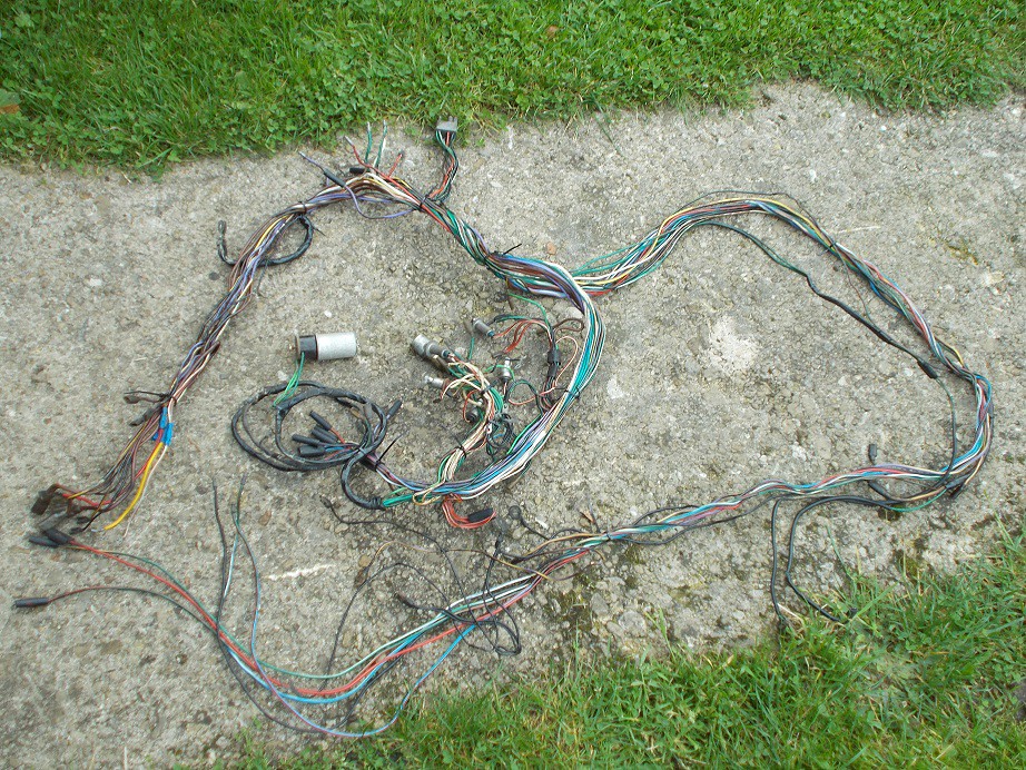
On Thursday I lay the front section of my pre-owned loom along the Monaco in a rough approximation of its eventual location. It was obvious that, due to the rearward cockpit position compared to the Spitfire, alteration was necessary. The choice was which side of the bulkhead to extend? Further close examination of the loom's layout compared to that of my dash blank and alternator/headlamps/indicators made the answer obvious. Both! I think I'm going to have to take it apart and rebuild it as I did for the rear section. When I was discussing buying the chassis frame I innocently asked the vendor if he had a loom - yes, I'll throw it in for another fifty quid he replied. It's definitely not for a Spitfire! However, the standardised colouring used in British cars of the period means that it's not difficult to work out what's what.

A marathon (albeit interesting and challenging) task awaits to brighten the dark winter days :)

DSCN0284 by Mick O'Malley, on Flickr

I couldn't use Phukubucket as it's been tweaked to prevent copying the url. The land of the free :rolleyes:. Not.

Regards, Mick
29 Sep 2017, 9:42am Engine Mechanical Overhaul Electrics Interior & Trim
More Looming

Over the last few days work on the front section of the loom has been progressing. My first task, after donning the customs officer gloves, was to remove both the self-amalgamating tape and the horrible sticky tape wound around each junction and terminus. I replaced the latter with loose-ish cable ties as I went along to preserve the layout.


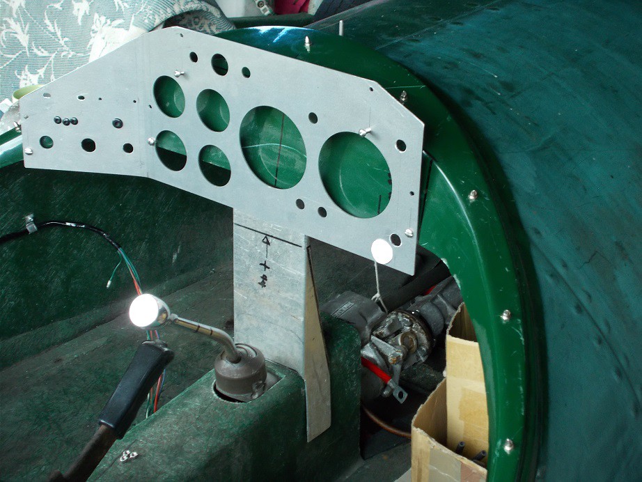
A couple of weeks ago I was pondering how to shoehorn my dash into the scuttle without its interfering with the gear lever/steering column brace/scuttle brace. I hit on the idea of having a bend in it in a similar fashion to my A352. I made a cardboard template marked with the instrument/switch locations and offered it up with a couple of trial folds before bending the real thing. Once I'd decided I clamped the dash blank to the workbench with a length of inch box packing and, using a block of 8" x 4" wood, bent it to the required angle. It will now sit further to the nearside with the instruments central.

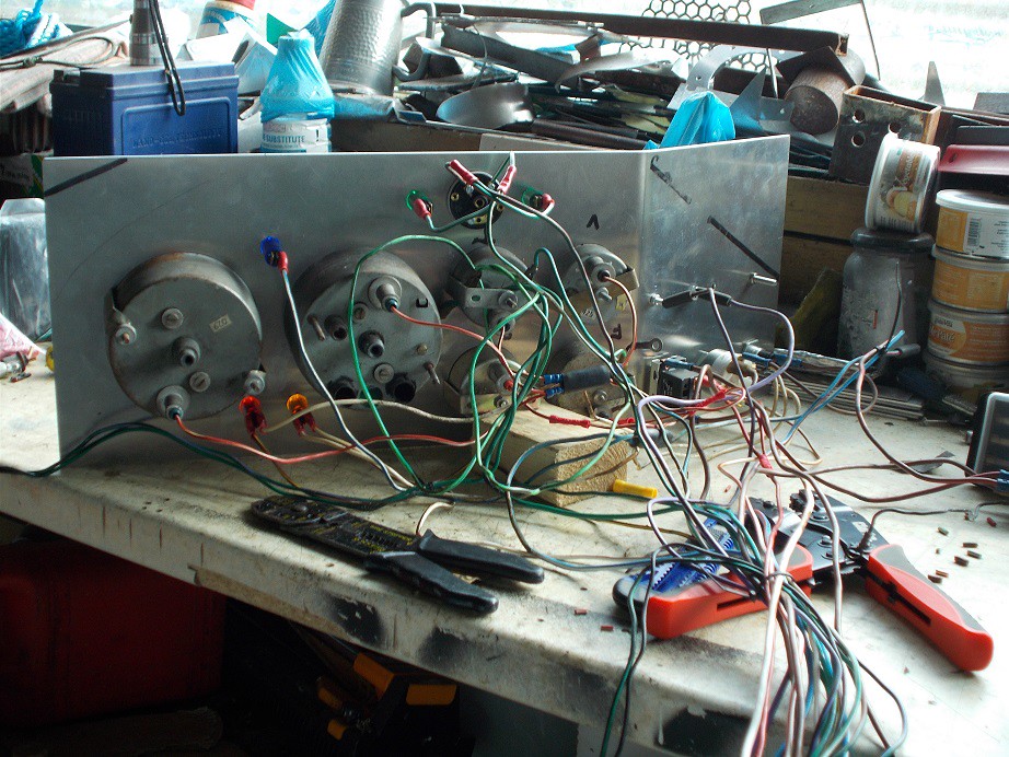
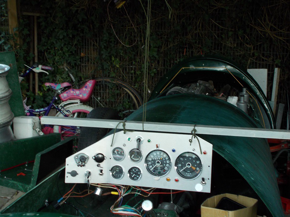
Next job was to fit all the clocks and switches to the dash, reverse it and lie the naked loom along in the correct orientation. I then commenced connecting everything, feeding the cables through the ties to shorten or lengthen them as necessary. I removed the redundant wiper wires whilst I was at it. I then realised that I hadn't made holes for the dipswitch and horn cables so I left sufficient slack in them to feed through. I searched in vain for a voltage stabiliser so bought a solid state one on eBay which arrived this morning. I've also ordered in-line blade fuse holders and a two pin flasher unit. I'll also need a switch, warning light and dash holes for the reversing lamp, as I hadn't originally anticipated fitting one.


The eagle eyed amongst you will have noticed that there are no earth wires - these will be the last fitments once I'm happy with all the positives. Hopefully, my next update will detail finishing the dash connections prior to moving on to the engine bay. Happy Days!

Regards, Mick

October 2017

3 Oct 2017, 5:50am Mechanical Overhaul Chassis and Body Interior & Trim
Dashing Around

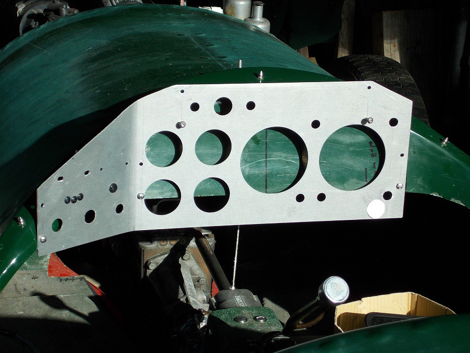
Yesterday I decided to bite the bullet, cut my dashboard to match the scuttle's profile, and temporarily fit it.

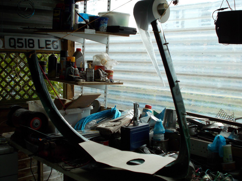
I first made a cardboard copy of the dash as the real thing's a little unwieldy, removed the scuttle and hung it over the workbench. I was then able to easily manoeuvre the cardboard until I was satisfied that it sat correctly. I then marked the top corner cuts and the mounting bolt holes and, after returning the scuttle moulding to the body, transferred the marks from the cardboard to the real dash.


I clamped the dash to the worktop and cut as much as possible with my jigsaw. The size of its shoe meant that I had to complete the longer of the cuts with my padsaw. I then filed the cut edges smooth and drilled the 5mm mounting holes.


I stuck the dash to the scuttle with loops of gaffer tape, carefully marked through the holes, drilled the fibreglass and loosely mounted the dash with M5 bolts.


Next job was to make a cardboard scuttle brace as a template before cutting the folded aluminium that will be the real thing. I stuck in in place with more gaffer tape.


I tidied everything away as I'd arranged to pick up an eBay item I'd won. It's a rear hub puller I need to replace the off side bearing on the A352 which was an advisory last test. The seller (and his wife, who immediately took some pictures) was very impressed with the beast. He opened his garage to reveal an Elan +2 in metallic blue with a silver roof. Beautiful! As ever, I hadn't taken my camera with me - sorry!

Regards, Mick
4 Oct 2017, 4:53am Chassis and Body Electrics Interior & Trim
Mr Thickie!!! (with apologies to Lt George)

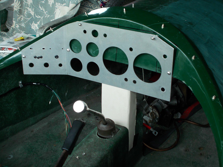
As I wandered down to the sunlit but somewhat chilly man cave yesterday morning I was feeling pleased with recent progress and was looking forward to finalising my dash and scuttle brace installation. This reverie was rudely shattered when I realised that I hadn't taken account of the steering column! Once my rage at my stupidity had subsided a little I pondered the options. Cut a hole for the column through the tacho. with a thermic lance? Probably not. More measuring (with brain in gear this time) showed that raising the dash by 44mm and cutting a recess for the column would solve the problem. Five new 5mm mounting holes later it was back in the car in its elevated position; the white paper dot being where the column will run. I'll probably fill the redundant holes with my dreadnought rivets.

I appreciate that it looks as though it'll be stuck out in the elements but the rake of the wind deflector will cover it nicely.


Luckily for me I'd suspended operations the previous day before cutting the scuttle brace which would, of course, have been too short. Half an hour with the jigsaw and files and it was resting in position :).


I then removed the scuttle with dash attached, hung it over the bench again and carefully marked the GRP where it will need to be cut for the gubbins sticking out of the back of the dash. This done, I remounted the clocks and switches into the dash, added the reversing light switch and warning lamp, popped the horn and dipswitch wires through their grommets, and set to with wiring the earths for the panel lights, voltmeter, accessory socket etc. Once again my new Machine Mart ratchet crimping tool came into its own: it really is light years ahead of the flimsy combination cutter/stripper/crimper I've used for the last five decades!

Once my newly made black insulated earth festoons were in place I called it a day.

Regards, Mick

p.s. Don't forget the Castle Combe Classic meeting this Saturday - unmissable!
5 Oct 2017, 6:05am Chassis and Body Electrics Interior & Trim
Getting There

Yesterday I set to with organising fitting the front portion of the loom. I first hung the dash with the loom attached from the cave roof in a close approximation of its final position - where would I be without Paracord! I offered up the section that connects (with a multipin) to the previously fitted rear loom, cut it to length, crimped it together and bound it with self-amalgamating tape. I could see that I'd shortly run out of this tape so whizzed indoors and bought a couple more rolls. Ten metres sounds a lot but it soon vanishes....


Every wire now unconnected runs forwards so I popped everything back on the bench and began organising them into two sets. The first and larger part will service the lights; indicators; horn; water and oil gauge senders; alternator and starter solenoid. I loosely cable tied these together and lay them out of the way. What remained are those that connected to the now redundant voltage regulator, fuse box and starter solenoid. I unthreaded the thin brown/green and brown/yellow wires which feed the ignition light, cut them to a suitable length and crimped them together. All the remaining thick brown voltage regulator wires have to be joined in a bundle. It was at this point that I remembered that I'd run out of both blue and yellow straight crimp on connectors which I'll also need for the fuse box wires. Another quick sortie to the computer for some Ebay-ing, paying the princely additional sum of 50p for 1c postage should ensure their arrival today.

As I'd reached an impasse on the wires themselves I dug out the remains of my galvanised 1mm steel sheet and cut some sturdy P clips to locate the chunky section of loom which will run forwards on the side of the passenger footwell. That was it for the day :)

Regards, Mick
6 Oct 2017, 6:02am Engine Chassis and Body Electrics Interior & Trim
Harry Houdini? Pah!

Yesterday, before I could thread the front section of the loom through the bulkhead, there were a couple of jobs that needed doing. The first was to bind the two wires which will go to the stop light switch as offering them to its location was one of the 'will it reach' questions I'll need to address.

The next was to make a suitable hole in the bulkhead. Taking the body off and plonking it on the grass with my ever willing son made this much easier. I decided to use the fuse box unit as an escutcheon as it has a neat jumbo grommeted hole. I made a cardboard template, taped it to the bulkhead next to the solenoid, felt tipped the outline onto the GRP, drilled 8mm corner holes and jigsawed them together. I drilled a 5mm locating hole in each long side of the fuse box, offered it up, drilled through the GRP and bolted it in, all done kneeling in the engine bay.

Now the the tricky bit. With the body back on the chassis I hung the dash and loom from the cave roof again. I could see that the tail of the rear section would need a couple more P clips so I cut, drilled and rivetted these in line with the others, at the same 16.5cm spacing. I knew I'd have to lie upside down in the driver's side footwell to thread everything through, and thought back to a couple of months ago when I last performed these gymnastics in the A352.

The pipe to the oil pressure gauge had started to leak at the block end so had to be replaced. The block end took about two minutes but fiddling about behind the dash with no elbow room was real trouble. My back took a good three days to recover from the insertion and extraction manoeuvres: I'm definitely not 21 any more!

With this in mind I lay a folded plastic groundsheet in place to provide slip as the GRP floor is quite grippy, donned head protection in the shape of a beanie, and wriggled into position. The wires behaved themselves at first but a snag presented itself: I'd neglected to remove the cable ties, these wouldn't fit through the grommet and I didn't have any tools with me, aaaaargh! Luckily I managed to worm my 'phone from my pocket and text my son who came to the rescue - his first words - "Are you stuck?" Once he'd passed me the necessary he took a picture of my undignified attitude. Chopping off the ties enabled the rest of the loom to be threaded through. I extricated myself, thankfully without lumbar trauma, and roughly lay the wires in position in the engine bay. The alternator; oil pressure sender and water temp. sender spades fitted fine, there's enough slack for the solenoid and horn connections, but the lights and indicator wires to the offside may need extending. I'd had enough by then so called it a day.


Regards, Mick

p.s. As a complete non-sequitur, whilst typing this BBC Breakfast TV ran an item regarding the new Concorde shed at Filton. I remember well many past visits to Castle Combe, where I'm headed tomorrow, when at around midday this iconic aircraft would pass high overhead on its way to New York. Happy Days!