I have made a little progress inbetween kitchen fitting. I have remade the lower steering column mount so it now clears the pedals. While I was at it I bent the clutch pedal so it is now a more sensible distance from the brake pedal. (Perhaps the original builder had big feet!)
 steering_column5
 by
Robin Martin, on Flickr
And it was pointed out to me that the angle that the steering UJ was running at seemed to exceed the 35deg recommended max. They were right! I have jiggled things a bit, mainly rotating the steering rack, and now the UJ is working within the 35deg. I could probably reduce the angle even further but I thought I would wait until a trial fit of the engine just in case I have to do any more rethinking of the steering shaft.
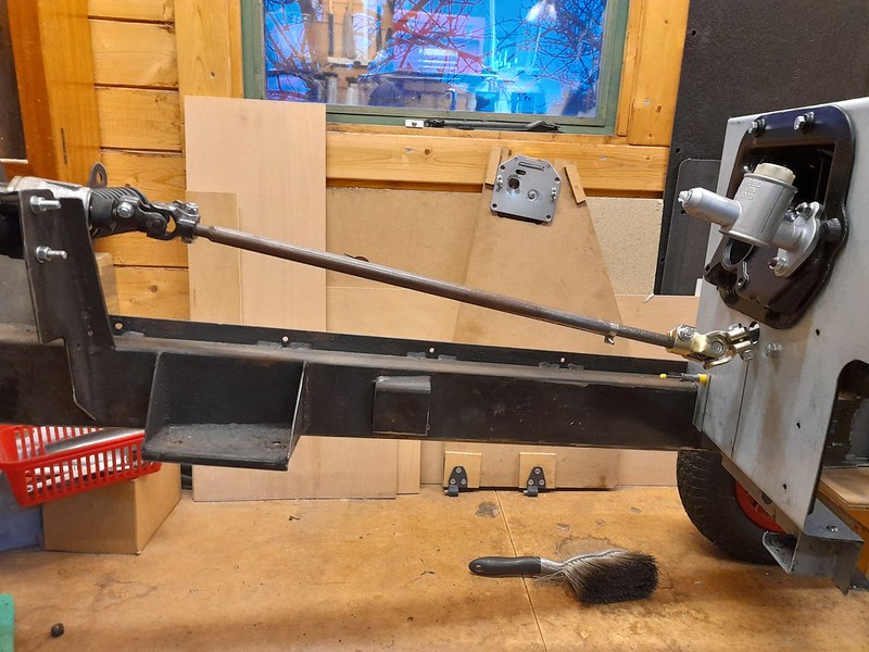 revised_steering_shaft
 by
Robin Martin, on Flickr
Now back to the kitchen fitting.... It's too cold in the man shed anyway :-)
Cheers, Robin
Took me a few minutes but I see what you mean. As far as I am aware it doesn't really apply to steering shafts. But I will do some Googling to check.
The problem with the first arrangement is that the UJ at the steering wheel end (the shiney new one) was running at about 38deg. According to the manufacturer (and some other wise sages :-) ) the maximum angle is 35deg otherwise you are in danger of wearing it out quickly and/or, in extreme cases, locking it up.
Cheers, Robin
Scuttle Top
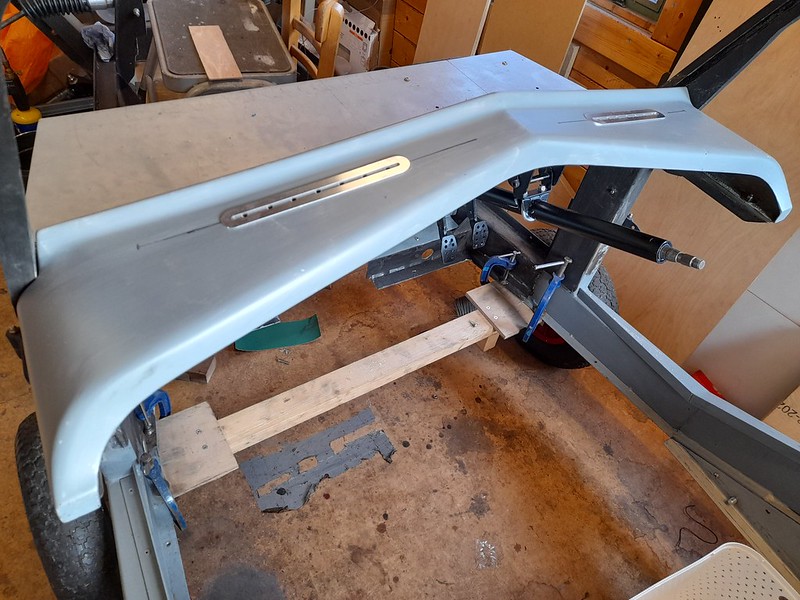
After a great deal of fitting and re-fitting I finally have the scuttle top fixed in place. It needed a lot of fettling to get it to fit and even now, if I was to be critical, its a little too narrow - it could do with being about 4mm wider.
 scuttle_top1
 by
Robin Martin, on Flickr
The front lip, which fixes to the bulkhead also is not flat and had to be pulled into place. I will have to bed it into some sealant when I finally fix it.
 scuttle_top2
 by
Robin Martin, on Flickr
I have also bonded in a couple of plenums so I can have windscreen demisters. I have drilled a series of holes in the scuttle top rather than cutting a slot. You can just see them in the first picture with a rather flimsy aluminium surround purchased from the well know kit car bits place, as were the plenums.
 demister
 by
Robin Martin, on Flickr
Kitchen now almost complete so I hope progress to be a bit faster. One can always hope...
Cheers, Robin
Door and windscreen frame
I have been making slow progress albeit going a bit from one thing to another.
The windscreen frame has to be one of the Roadster's main features doubling up as a roll bar. However I was never very happy with it in the "raw" state. It is bent from a solid steel bar with a slot milled on the inside to take the screen. This left very sharp edges and some hollows in it from the bending process. So I have taken the angle grinder and P38 to it. Looks much more acceptable now.
 windscreen_frame2
 by
Robin Martin, on Flickr
 windscreen_frame1
 by
Robin Martin, on Flickr
I have also completed a prototype door. The plan is to use a solid plywood core as in the original Marlin supplied door. However decent plywood is sooooo expensive now I made the proof of concept door from MDF. I have now skinned it in alluminium (left over from the Pembleton build). I am pretty pleased with the result and now happy to take the saw and router to the final plywood version. The latch is from a landrover, modified by removing the outside handle and lock barrel. I was going to use a Morgan latch but they are now over GBP70 each whereas the landrover one is GBP30.
 door_prototype1
 by
Robin Martin, on Flickr
 door_prototype2
 by
Robin Martin, on Flickr
Cheers, Robin
Engine
Never buy an engine from ebay and someone you don't know were the words echoing in my head as I handed over my hard earned.....
Anyway the story is BMC 1800 engine (Marina, MGB etc.) for sale on Ebay. It had an almost unbelievable spec with a Vulcan gas flowed head, Piper camshaft etc etc and had never been run since its rebuild. Of course I smelt a rat particularly as it had had a quick blow over with black paint. Anyway - I persued it and the story had a certain ring of truth. Advertised by an older, and and possibly a bit naive, guy. He had purchased it for his MGB but then found it was originally from a Marina TC and wouldn't fit. The crankshaft spigot bearing is much smaller for a Marina. So he decided to sell it on Ebay and, not suprisingly as it wouldn't easily fit an MGB, hadn't had a lot of interest. So a bit of negotiation ending up in a price that was far less than what just the head was worth and the engine was mine. He even delivered it.
Today I couldn't resist any longer and started the checking process. The plan is to dismantle and re-assemble it anyway not trusing work that someone else has done. An engine built to this spec should have certain features, double valve springs, duplex timing chain etc. And I am pleased to say it all looks good so far!
The head has clearly had a lot of work - you can see the porting through intlet and exhaust ports.
 engine4
 by
Robin Martin, on Flickr
 engine3
 by
Robin Martin, on Flickr
And it has the requisite double valve springs and duplex timing chain.
 engine2
 by
Robin Martin, on Flickr
 engine1
 by
Robin Martin, on Flickr
The next step is to get it on to the engine stand and pull it apart a bit more. But so far looking good.....
Cheers, Robin
Head Completed
I have now completed the dissassembly and reassembly of the head. It's now resplendant in MGB maroon which I understand would have been the original colour. Everything looked pretty good. The head has been gasflowed to what I suppose is stage 2. I am no expert but it looks pretty much as Peter Burgess describes in his MGB tuning book with the exception of hardened exhaust seats which it doesn't seem to have. Which leads me to think all the work on it was done many moons ago.
 stripped_head
 by
Robin Martin, on Flickr
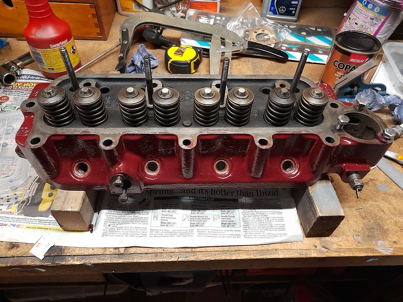 reassembled_head
 by
Robin Martin, on Flickr
During the strip and reassembly process I also cleared out all the waterways by blanking off the thermostat position and filling it with a solution of Rust Destructor and letting it soak for several days. It seems to have done the trick.
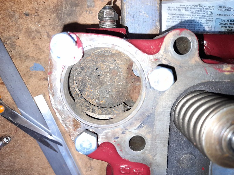 derusted
 by
Robin Martin, on Flickr
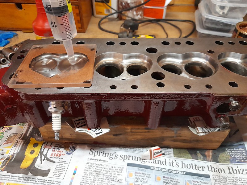
While I was at it I also measured the combustion chamber volumes so I could work out the compression ratio.
 combustion_chamber_vol
 by
Robin Martin, on Flickr
Using the formula in Peter Burgess's book:
Engine size with +30 overbore = 1834cc. Cylinder swept area = 458.5cc
Combustion chamber volume as measured = 41cc
Clearance volume = 6.5 + 2 + 4.5 + 41 = 54cc
Compression ratio = (458.5 + 54) / 54 = 9.49
While I was at it I though it would be fun to work out the potential 0 to 60 time. Again using a formula from Peter Burgess.
0 to 60 = (2 x W / T) to the power of 0.6
W = weight – say 750 kgs = 1650 lb
T = torque – say 120 lb/ft (figure from Peter Burgess book for an engine with similar configuration)
0 – 60 = 7.3 seconds
So - no slouch then....
Cheers, Robin
I have been looking for ideas that would help to bring the exhaust out of the side of the car as Marlin intended. Marlin supplied a special exhaust downpipe which allowed this but it was a very tortured design and probably not good for gas flow. And of course it's long since you could obtain it. I even tracked down the manufacturer (Double S) and they confirmed that had binned the pattern. But after a lot of Googling and general phaffing about I have purchased this exhaust manifold - currently on its way from the USA.
 patriot h4800 exhaust
 by
Robin Martin, on Flickr
It's a 3 into 1 design, ending in a 2" pipe, that hugs the block. I reckon with a bit of luck I should be able to bring the exhaust out the side either under or over the chassis rail.
So the next question is does anyone have any experience of silencers? There are loads for sale on Ebay, most of which I guess are from China and of dubious quality. I am looking for something that is not outrageuosly loud, but not too quiet either.....
Cheers, Robin,
Yes I think SS made the complete system. But, although they remember making it, they no longer have any of the patterns. Or so they told me.
Cheers, Robin
I have pretty much finished the engine build now other than the water pump and sump.
The sump I have to swap from the original engine as the one that came with the replacement had been buchered somewhat. A bit of a pain as it means I will need both engines in the air at the same time in order to do the swap.
The water pump hmmm... the one I purchased from a well known MGB parts specialist was rubbish - the casting looking like a copy of a copy of a copy... But I think I have located something better now.
You can see from the pictures that I forked out on a vernier timing wheel. Reground camshafts (so I am told) frequently need the timing tweaking to get it 100% correct. Certainly true in my case as when I had selected the specified advance it was nowhere near where it would have been if I used the two dots on the original chain wheels.
And finally I couldn't resist trial fitting the exhaust manifold I purchased from the states. The hope is that this will help me get a side exit for the exhaust without too many tortuous turns or any cutting and shutting of the exhaust system.
 timing1
 by
Robin Martin, on Flickr
 engine6
 by
Robin Martin, on Flickr
 engine7
 by
Robin Martin, on Flickr
 engine5
 by
Robin Martin, on Flickr
And finally - purchased these from Ebay. Already a bit of a bargain, the guy that makes them reduced the width so they would fit the Roadster - FOR FREE!
 seats
seats by
Robin Martin, on Flickr
Engine build now complete. Been a bit delayed with problems caused by poor quality parts. As the MGB is so popular you wouldn't think it would be a problem but there is pretty much nothing available from the "normal" aftermarket and everything seems to come from China. Having said that some of it is very good, but some of it absolute rubbish...
I have fitted a fancy rocker cover as the original was a bit bent, but in fact it is not a great fit so may go back to the original. And a new distributor which has an advance curve (allegedly) tweaked for stage 2. Was rather cheap though, although it looks made well enough, but it will be another 12 months or so before I can verify its operation. In the meantime I will have a go a stripping and rebuilding the original.
Some pictures.
 engine10
 by
Robin Martin, on Flickr
 engine11
 by
Robin Martin, on Flickr
The observant may notice the non-standard engine mounting rubbers. The original Marina ones are like rocking horse poo and so I have used Land Rover ones as suggested by the original Marlin build manual. These have the added advantage of lowering the engine slightly which I hope will give enough clearance for the fron carb to fit under the bonnet. The original bonnet had a couple of unslightly bulges.
Virtually zero progress on the Marlin recently due to holidays and having to catch up with some DIY stuff round the house. Oh - and I managed a freak accident and very nearly cut the tip of my thumb off. Arghh. But I have made these. Any guesses as to what they are. Hint - nothing to do with cars.
 tubes
tubes by
Robin Martin, on Flickr
Bit of a giveaway now as to what they will be...
 first_fit
 by
Robin Martin, on Flickr
Trunions....
After several months of DIY I finally have some time to spend on the Marlin. I really should be completing the resto of the chassis but I fancied something a bit more interesting so decided to trial fit the front suspension. The Marina uses an odd setup for the front suspension using torsion bars and trunions, based on that used by the Morris Minor but, unfortunately, having no common parts. Parts are as rare as hens teeth....
The standard problem with the upright is lack of maintenance causes the lower thread on the upright to deteriorate. Ultimately the trunion can part company with the upright. Mine were no exception.
 upright rusted thread 2
 by
Robin Martin, on Flickr
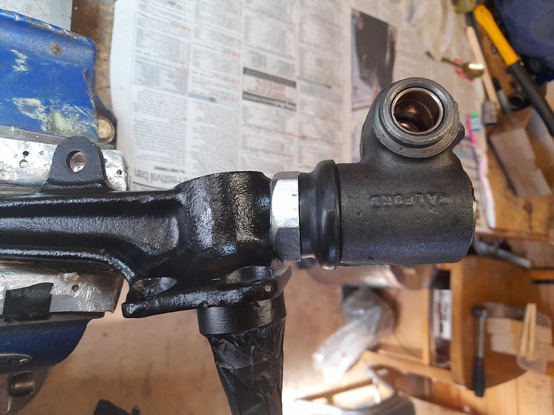
I was able to track down, thanks to the Marina Owners Club, some new old stock of "Walford Trunions" which were a period fix for the problem. Basically a new threaded sleeve is screwed on to the old damaged thread and a new oversize trunion fits to that.
 original and walford trunion
 by
Robin Martin, on Flickr
You are supposed to fit the new threaded sleeve using the supplied threadlock but that was a bit suspect being 30+ years old so instead I bonded it using an industrial Araldite. Jobs a good-un. I should say that it is also tightened up to 100 Lb/ft as well!
 inner component of walford trunion
 by
Robin Martin, on Flickr
 walford trunion fitted
 by
Robin Martin, on Flickr
Finally I fitted all the bits up to the car. The Marina uses a lever arm damber but on the Marlin this is replaced by a Mini upper suspension arm and a conventional damper (not fitted yet)
 front suspension trial fit
 by
Robin Martin, on Flickr
The critical point is that the torsion bar should pass through a hole, on the chassis where it is finally fixed, without any lateral or vertical tension. This is also the rubbish part about Marina front suspension as it makes it pretty much impossible to play with the castor or camber. Anyway after a bit of fettling it's a great fit.
 torsion bar position
 by
Robin Martin, on Flickr
Now that I am happy it fits, and I am not missing any major bits, I can take it all off again and complete the cleaning up of the chassis!
Cheers, Robin
The upright rotates in the trunion using the thread. It effectively un-screws and screws-up a little every time you turn the steering wheel. It's ancient technology inherited from the Morris Minor. Quite why they didn't fit a balljoint instead I will never know. There is a massive balljoint at the top of the upright where it joins to the top arm. They could have put similar at the bottom.
The thread is lubricated using one of the 2 grease nipples on the trunion. The original design only had a single grease nipple which is why not much grease ever reached the thread. And made worse by lack of regular maintenance.
My guess is that the majority of Marinas still out there have worn threads on the upright. I think as long as you fill them full of grease before the MOT the tester doesn't notice.
Cheers, Robin
More refurb work
Doing a bit more on preparation.
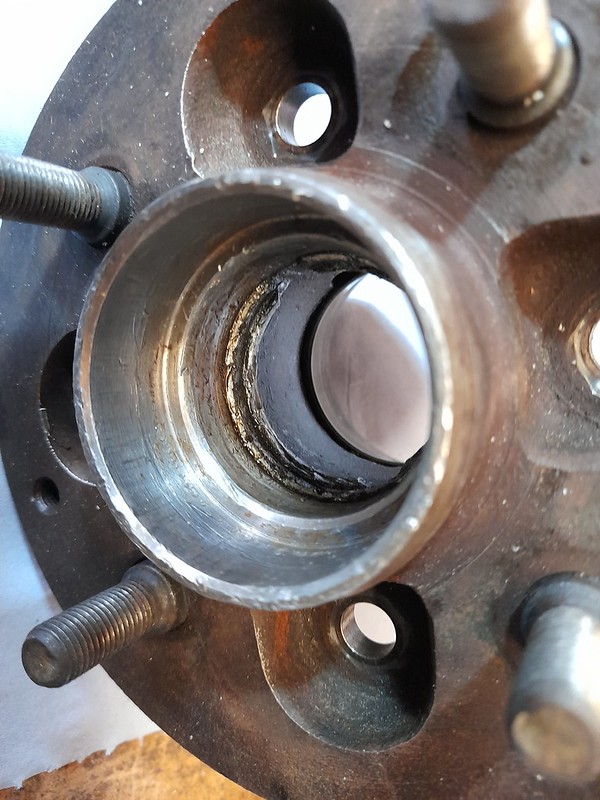
First the front hubs. The good news was they still had the original Timken bearings - or so I thought.... However when I looked at one of them it was totaly trashed inside. It looks like a bearing had broken up at some time judging by the damage. Even the step which locates the bearing outer race was destroyed. Someone had done a quick fix and popped in a new bearing but that's not really an acceptable solution so I am looking for a replacement.
 damaged hub
 by
Robin Martin, on Flickr
And the brake calipers. They are almost the same as those used on the Triumph Spitfire (Girling type 14) so there are plenty of replacements available. But, after experience with buying bits for the engine I am a bit suspicious of some of the stuff that is available. So I thought I would have a go at stripping them - keeping in mind they are at least 50 years old and haven't seen any use for at least the last 30!
Following a good tip I cut the end off an old flexi brake pipe, screwed the uncut end into the caliper and used my compressor to blow down the other. This allowed me to have the caliper safely in a bucket at arms length just in case any of the pistons came flying out!
Three of the four came out "easily" but the last one wouldn't budge.
Now I followed another good tip! I put back the piston in the caliper with the stuck one but in an almost out position. I then filled the caliper with water (yes really) with the bleed nipple screwed up and then a spare bleed nipple where the brake line should go. I used a couple of clamps to push back the "good" piston and Hey Presto the water pressure was sufficient to get the stuck piston moving! Amazing!
Finally I split the calipers. You are not supposed to do this but I couldn't see any other way of properly inspecting and cleaning the bores. There is only a single O ring to worry about and this comes with the refurb kit you can get from Bigg Red. And, suprise suprise, everything looks good even though there was rusty crud in most of them!
 stripped calipers
 by
Robin Martin, on Flickr
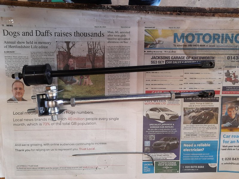
I have made some new adjustable tie bars following what has been done in the past by other Marlin owners. They comprise the front part of the old tie bar, a turnbuckle and some rose joints. The idea is not so much to make the suspension adjustable but to be able to dial out any inaccuracies in the chassis geometry. From what I have read this is not uncommon. I am going to remake the U shaped chassis brackets as I don't think my first attempt looks substantial enough.
 tie_bar1
 by
Robin Martin, on Flickr
 tie_bar2
 by
Robin Martin, on Flickr
Cutting the 1/2" UNF thread on the tie bar proved tricky. Ideally a lathe should be used for larger external threads but I don't have one. I do however have a decent pillar drill - so I used this to drill a perpendicular 1/2" hole through some substantial box section. I then attached this to the die holder positioning it with a 1/2" UNF bolt. The hole through the box section acts as a guide resulting in a perfect thread on the item to be threaded.
 modified_die_holder
 by
Robin Martin, on Flickr
 die_holder_use
 by
Robin Martin, on Flickr
I should say the guide wasn't my idea. I found the basics on t'internet after a failed attempt at cutting a thread.
Yes - over simplified description! Once positioned using the bolt, you attach the box section guide to the die holder using whatever mechanism suits. I just drilled through the die holder and box section and use a couple of M4 screws.
Cheers, Robin
Front suspension rebuild has moved on to fitting the hubs. At this stage I was feeling fairly smug with the bargain triumph wire wheel adapters I had bought from Ebay as a trial fit seemed to be good.
However when I came to fit them properly I found they didn't (fit). The hub casting, where the grease cap fitted, fouled the inside of the adapter. "Easily" fixed by some heavy duty filing. I then found that the wheel studs have a large shoulder on them, great for centering the wire wheel adapter, but unfortunately preventing the nuts securing the adapter to be screwed fully home. Hmmm. after some head scratching I made a thin, 1mm, spacer which did the trick. now everthing fits OK :-).
So the front suspension is pretty much complete and I would have a rolling chassis - if my wheels had any tyres on them,
Some pictures....
 hub_before
 by
Robin Martin, on Flickr
 hub_and_spacer
 by
Robin Martin, on Flickr
 front_suspension1
 by
Robin Martin, on Flickr
I have been making slow progress once again. This getting old certainly slows things down a bit. Plus the more than occaisional holiday...
The chassis is finally all cleaned and primered. I am going to coach paint the bodywork so I thought I would practice on the chassis. This means a further coat of primer, 2 x undercoat and 2 x topcoat. Could take some time, especially as I am going to do it in two halves - first the front as far as the windscreen and then the rear. There is a convinient weld in the chassis at this point to which I can paint up to. I have also painted the front and rear bulkheads. I remade these from zintec some time ago and, although rust resistant, are not rust proof.
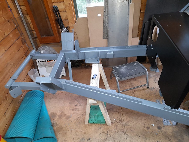 chassis_in_primer
 by
Robin Martin, on Flickr
The plan was always to convert the car to cycle wings but I have seen a few Marlins where this has been done but where the rear wings were retained. So I have dug them out of the weeds and given them a clean. Before and after picture.
 rear_wings_clean
 by
Robin Martin, on Flickr
One of them though has a real bodge with part of it being ground away. I assume this was to aid fitting - who knows. Anyway, I don't like bodges so I have started to repair this.
 rear_wing_bodge
 by
Robin Martin, on Flickr
While the fibreglass is out, and my hands itching, I am also modifying the radiator surround, no pictures yet though...
After a considerable ammount of fettling I finally have an acceptable radiator surround.
It was orginally fitted very badly and I struggled to get a better fit until I finally discovered the whole moulding is on the sqiff! Once I had worked that out I managed to get a reasonable fit although still not 100% square at least it looks OK to the eye. In the process I filled many holes and extended the sides down so they touch the chassis rails. Needed as I will be using cycle wings so this part will be visible. I also did a bit of re-inforcing arround the edges and filled in the gap that is normally visible between the front horizontal edge and the bumper. (Later cars have a neater wrap arround bit that fitted arround the bumper and provides somewhere to mount the number plate.)
 rad_surround
 by
Robin Martin, on Flickr