Week 20 update.....
well to be honest, I don't have a lot to show for the last couple of weeks due to a combination of the weather and 'domestic things' taking up my spare time.
But I have reached a significant milestone.... I've finished painting the chassis and the build can now begin

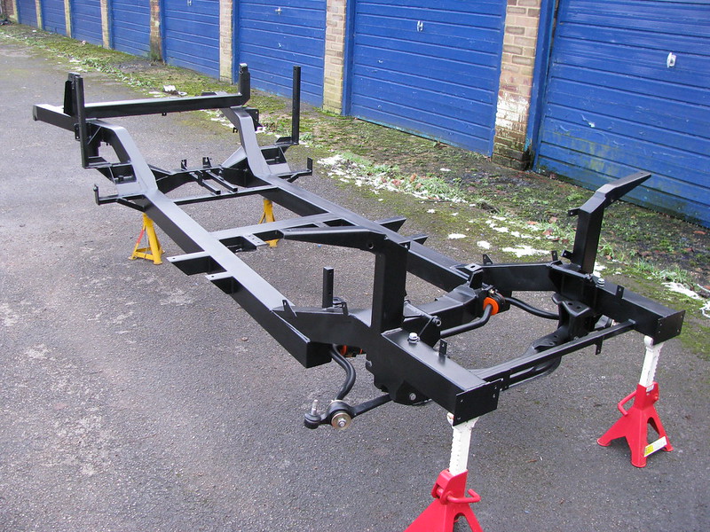 Chassis - painted!
 by
marlinpeter, on Flickr
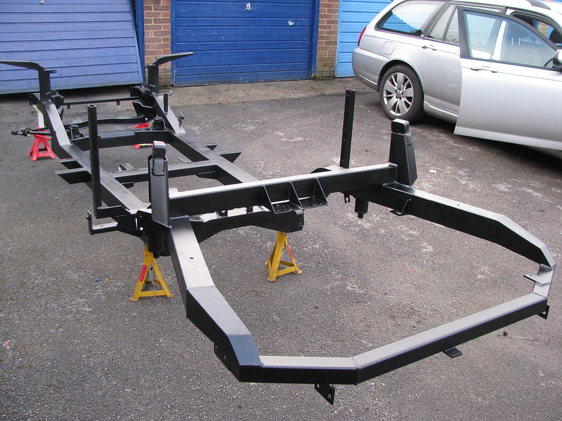 Chassis - painted!
 by
marlinpeter, on Flickr

.......peter
Probably not as my Marlin Sportster is almost the same colour.
I quite like the 'two-tones' but really that decision is a long way off
 Royale Sabre kit-car
 by
Albert S. Bite, on Flickr
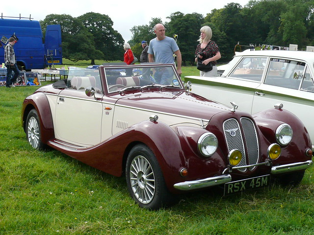 Vintage Car - Royale Sabre [RSX 45M] 110710 Leighton Hall
 by
maljoe, on Flickr
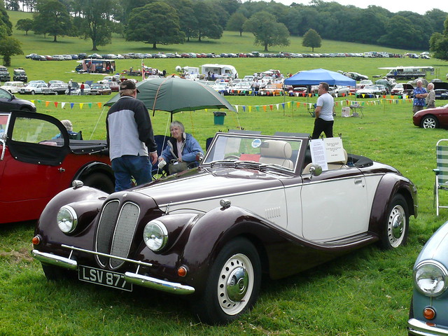 Vintage Car - Royale Sabre [LSV 877] 110710 Leighton Hall
 by
maljoe, on Flickr
It'll be on steel wheels or or maybe wires, but the colour options are still wide open.
I hope to see some finished cars at shows this year before making up my mind.
Fun down at the lockup
It was fun down at the lockups this morning.....
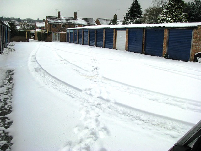 Fun in the snow
 by
marlinpeter, on Flickr
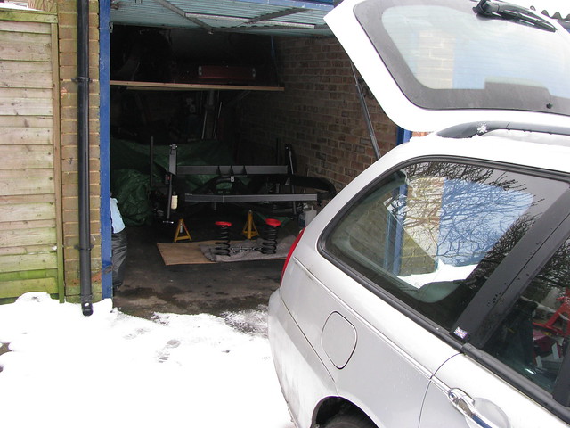 Fun in the snow
 by
marlinpeter, on Flickr
Week 21 update......
After finishing the painting last week meant that I could get back to spannering and start bolting bits back together.
First up was refitting the rear beam followed by the two trailing arms and (temporarily) the shock absorbers.
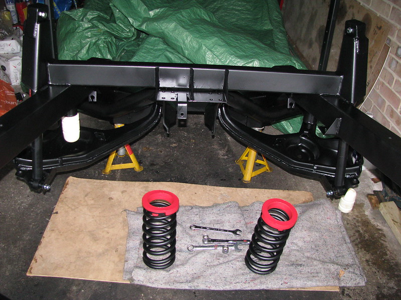 Rear beam and trailing arms
 by
marlinpeter, on Flickr
The rear bump stops are as rare as 'hens teeth'.
Unfortunately, the shocks that came with the kit were for a Granada and the wrong length for the Sabre, so I decided to try these Japanese KYB shock absorbers.
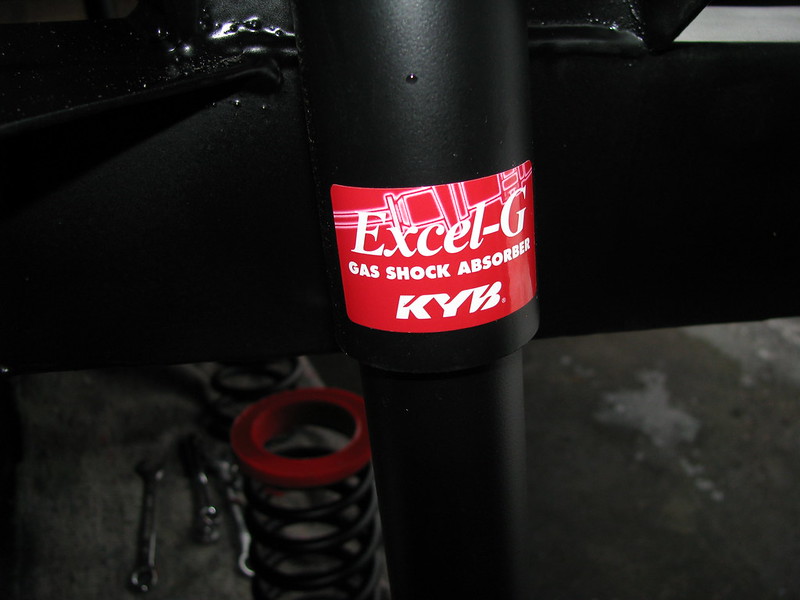 Shock absorbers
 by
marlinpeter, on Flickr
After a trial fit of the rear beam, it became clear that I needed the top part of the bush.
 Rear beam poly bush
 by
marlinpeter, on Flickr
 Rear beam poly bush
 by
marlinpeter, on Flickr
View from below. The smaller bolts are 7/16 inch UNF but I have no idea why.
Rear hubs have been refurbished with new bearings and grease seals.
 Rear hubs fitted
 by
marlinpeter, on Flickr
I've fitted the differential/final drive but the bad news was that the Floflex mount didn't fit so I've put the Ford part back.
 Final Drive fitted
 by
marlinpeter, on Flickr
Next up will be the rear springs, half shafts and then a quick go round with the torque wrench before putting the rear wheels back on.
........peter
Thanks for the feedback.
A quick summary for you and anyone else joining the story late.....
The Royale Sabre Chassis was made in 1994 and the build presumably started shortly after. The car was upholstered in 1997 but the car was never finished or registered. The story I was told was that the guy building it didn't put any antifreeze in the cooling water which froze and split the engine block. After that he lost heart and never finished it. It then languished in garages or under tarpaulins until I bought it last August (2012).
So yes, it will now need IVA testing before I can register it.
Enjoy your IVA

...peter
Thanks, Patrick.It's certainly coming along nicely now but I can't wait to start playing with engines again
Week 22 update.
This week I've refitted the rear springs and drive shafts.
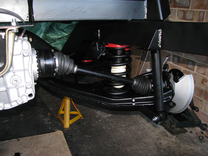 Rear springs and drive shafts
 by
marlinpeter, on Flickr
Which means that I now have a rolling chassis again!
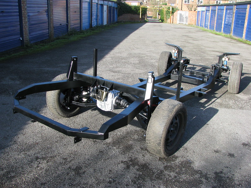 Rolling Chassis complete
 by
marlinpeter, on Flickr
Now I can get back to engine fitting trials
........peter
Week 23.
Sorry no pictures this week. I've been working on an issue with my front hub bearings but nothing new to see at the moment.

....peter
Week 24 update.....
And so on to the engine trial fitting....
The Royal Sabre chassis that I have, was designed to take the Ford 'Cologne' V6 engines. These engines are very heavy and relatively low power for their CC. They are also hard to come by in good condition and second hand ones on ebay can be a bit of a gamble. Other Sabre builders have used the Rover V8 engines but my preferred choice at present is the BMW M52 in the 2.8 variety. These make 190BHP in stock form and there are plenty of cars about to choose an engine from. If I can get an early 1995 model I might escape having to fit cats. The Sabre gearbox tunnel will likely need some modification but as this is made of fibreglass and not structural it should be relatively easy to modify.
The big question still to be answered is whether the M52B28 will fit and still have room for the brake servo due to its 30 degree slant mounting angle. I have a 'gash' M52 engine from a previous abandoned project that I'm going to use to see if it all fits before committing to the final engine.
So I first bolted together the gash engines sump, block and gearbox. I then rested this combo on a 10mm thick offcuts of MDF on the chassis crossmember. I need to get the engine as low as possible but still need some clearance for the engine to 'rock' under acceleration. I'm using very stiff Land Rover engine mounts so there shouldn't be much vertical deflection.
I then cobbled together a gearbox mount from a Marlin part and some old Ford parts to bring the engine block level.
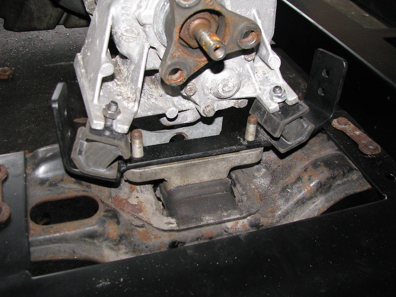 Engine fitting trials
 by
marlinpeter, on Flickr
This combination created just the right height to get the engine block level. A more elegant mount will be made if this works.
(Since posting this picture on my Flickr site, Ian (Morris) has pointed ot that the BMW engines are mounted in their cars with the back of the engine sloppy down by about an inch, so I will experiment with dropping the back of the gearbox down further but I'm concerned about the propshaft working angle deltas.)
I then made up some 'stays' to hold the engine in the right position and at the right cant angle. Even without the cylinder head it tends to roll over if not supported.
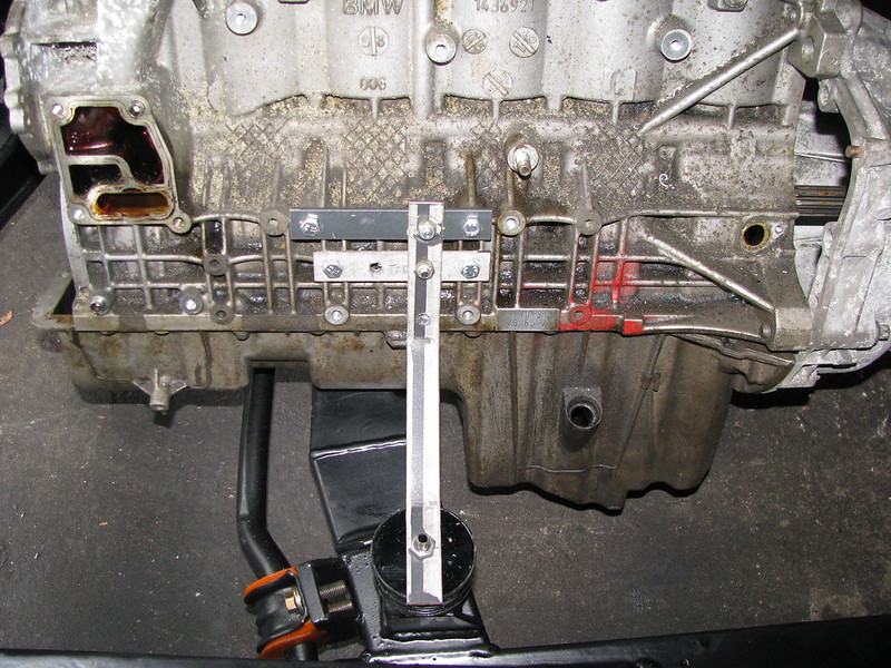 Engine fitting trials
 by
marlinpeter, on Flickr
 Engine fitting trials
 by
marlinpeter, on Flickr
The disposable stays are able to be adjusted fore and aft and sideways. Since taking this shot I've slotted the holes on the stay to the rubber mount so I can adjust the engine side to side.
 Engine fitting trials
 by
marlinpeter, on Flickr
 Engine fitting trials
 by
marlinpeter, on Flickr
Now I've got the engine in position, the next job will be to refit the body tub and see where I need clearance. That's a job for the weekend when my sons are around as it's a three man job!
I've also now swapped my Granada power steering rack track rods for the ones from the Sierra manual rack. This has given me the correct track width to adjust the front wheel toe-in correctly. The track rods have the same screw fitting inside the rack so it was an easy swap.
....peter
Hi Robin,
yes, assembling the engine bits 'in situ' is much easier as I can lift the alloy block without a crane but probably not advised for an engine you plan to use as you can see rust forming on the parts.
Your welcome to come have a look whenever you like....
...peter
Hi Mark,
firstly, welcome to Madaboutkitcars and it's great to meet another Sabre builder. You are the second to contact me in the last two weeks so there are are a small group of us either building or restoring Royale Sabre cars.
I'd be happy to answer any questions that I can, but bear in mind that I'm still learning myself. Other sources of info are from the Royale Owners Club who are a very friendly bunch and also the current manufacturer (ACL) run by Malcolm Badger.
http://www.royaleownersclub.org.uk/index.asp
http://www.automotivecreation.com/
Malcolm has now a comprehensive list of parts on his website above and I'm sure he will help if he can.
Let's see some more info and pictures of your Dad's car and send me a PM if you want my direct email address,
...peter
Week 25 update.....
This is going to be a major update so let's see if I can get it all done in one update
(I might need to split it if there is a limit on the lines of update).
The week started off with the Flo-flex differential/final drive mount that didn't fit. I made up a spacer a couple of weeks ago and decided to fit it before re-fitting the body tub.
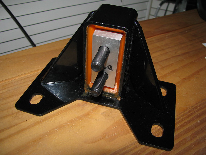 Diff mounting spacer
 by
marlinpeter, on Flickr
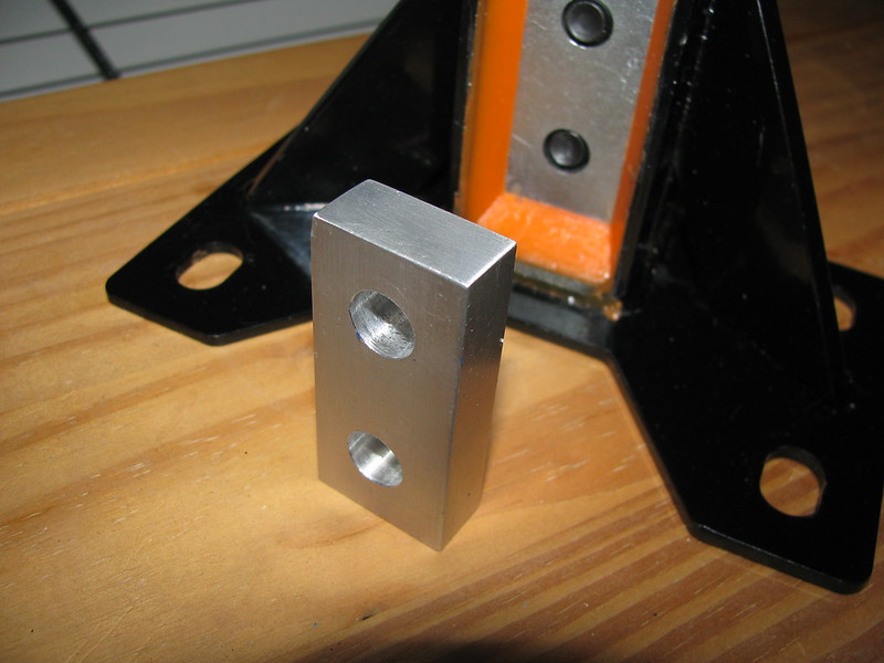 Diff mounting spacer
 by
marlinpeter, on Flickr
It now all fits OK. There was some lateral misalignment of the mounting holes which is possibly why the car came with 8mm bolts fitted. I filed out the chassis holes to align to the mount holes so that I could fit 10mm bolts and nylocks.
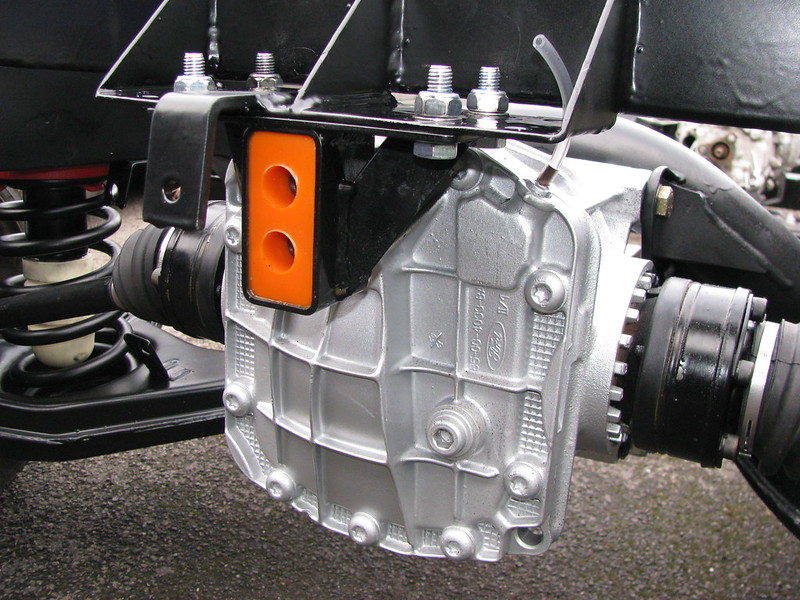 Diff mounting with spacer
 by
marlinpeter, on Flickr
Next up was the body mounting foam. The build manual calls for body mounting felt which I couldn't find anywhere so I've used some handy self adhesive 3mm thick closed cell foam. It was easy to use and went on a treat.
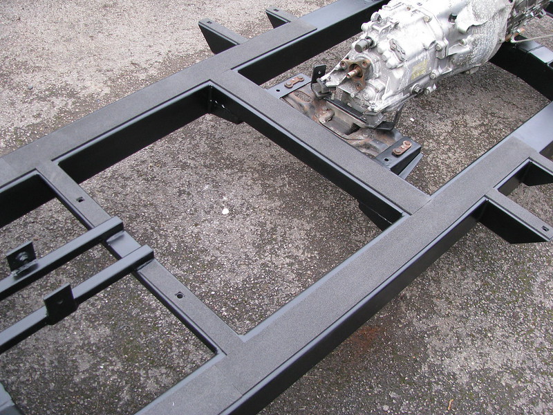 Body mounting foam
 by
marlinpeter, on Flickr
 Body mounting foam
 by
marlinpeter, on Flickr
Then , Saturday morning my two sons were 'press ganged' down to the lock up to help me lift the body tub back on to the chassis to be able to press on with the Engine fitting trials.
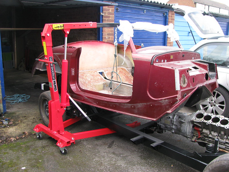
The first problem was that the gearbox tunnel fouled on the Marlin gearbox bracket that I had co-opted, so that had to be removed straight away. Here you can see me using my engine hoist to lift the body up for me to work on the gearbox mount underneath.
 Body lift!!
 by
marlinpeter, on Flickr
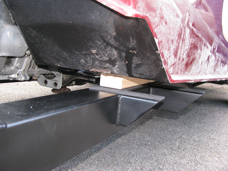
After removing the gearbox bracket, the next obstruction is the top of the gearbox tunnel rests on the top of the gearbox so I've put these 40mm thick blocks of wood to hold the body tub clear.
 Next problem....
 by
marlinpeter, on Flickr
Problem three.....
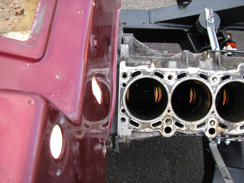
....the next problem was that I had mounted the engine too far back to fit the cylinder head. I had to modify my 'engine stays' to move the engine forward by 20mm leaving a 5mm gap between the sump and the large chassis cross-member.
 Problem three.....
 by
marlinpeter, on Flickr
Problem four....
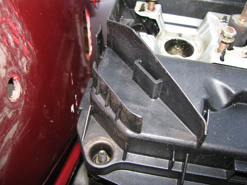
The next problem after fitting the cylinder head is this bit of cover guide gets in the way of the brake servo.
 Problem four....
 by
marlinpeter, on Flickr
I took a saw to the offending bit of plastic. I don't think it is important.
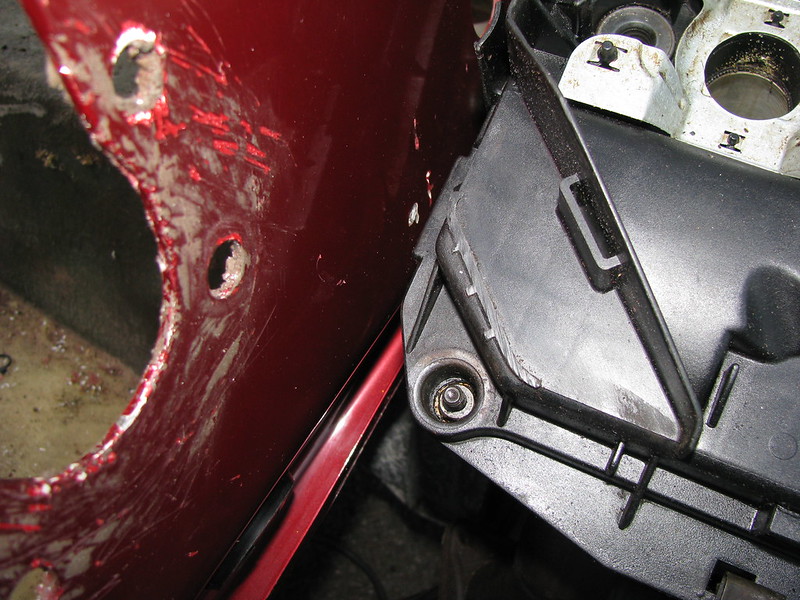 Problem four...fixed
 by
marlinpeter, on Flickr
I think i'll pause here so I don't lose the whole update.....to be continued....
Week 25 update .... part 2!
After lots of trial and error in the foot-well and modifying holes and drilling new ones I managed to get a position for the servo.
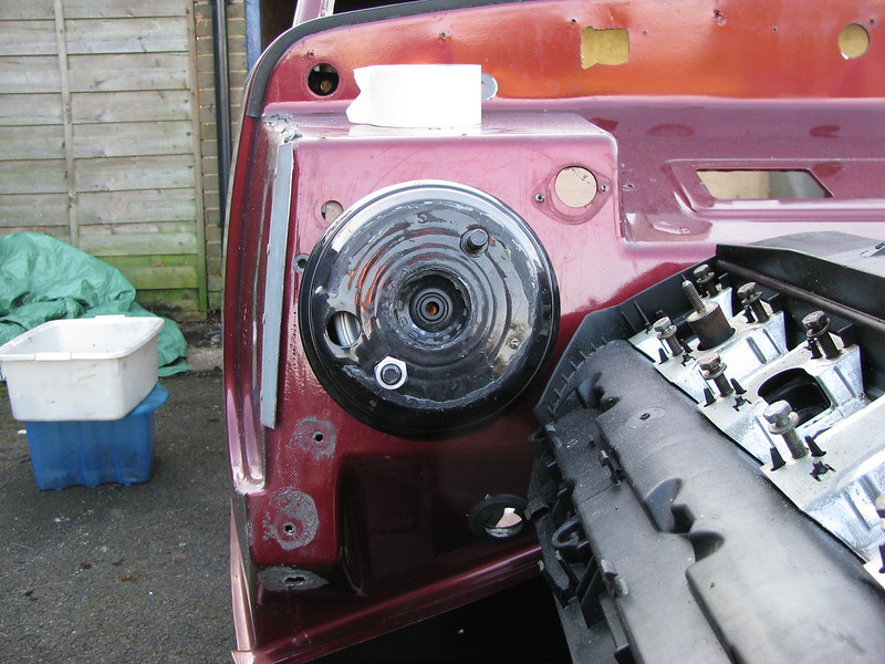 Servo positioned
 by
marlinpeter, on Flickr
Brake master cylinder - I can't see any issue fitting this with its reservoir fitted.
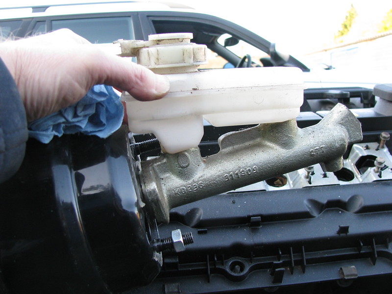 Brake master cylinder
 by
marlinpeter, on Flickr
I had to position the pedals as far to the right and as high as possible to create the best possible chance of fitting the servo. (the MDF is only temporary!!)
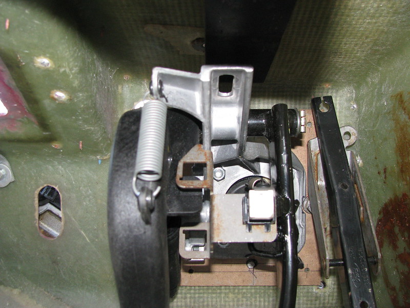 Pedal box
 by
marlinpeter, on Flickr
Pedal positions need a bit of work but it shouldn't be too difficult to achieve a better spacing. They are also a bit high so I might need a spacer block under the carpet on the floor.
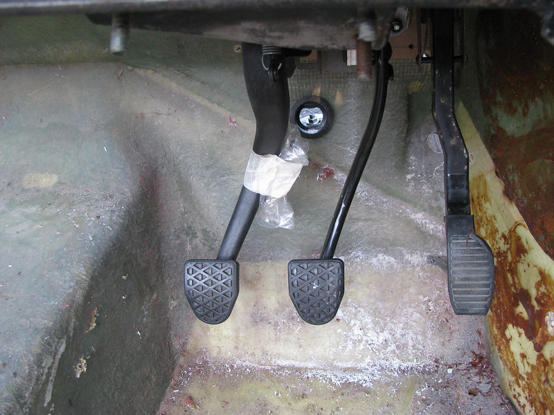 Pedals
 by
marlinpeter, on Flickr
I can just about get the rocker cover on and off with the servo in place but not much clearance for the engine to rock sideways?
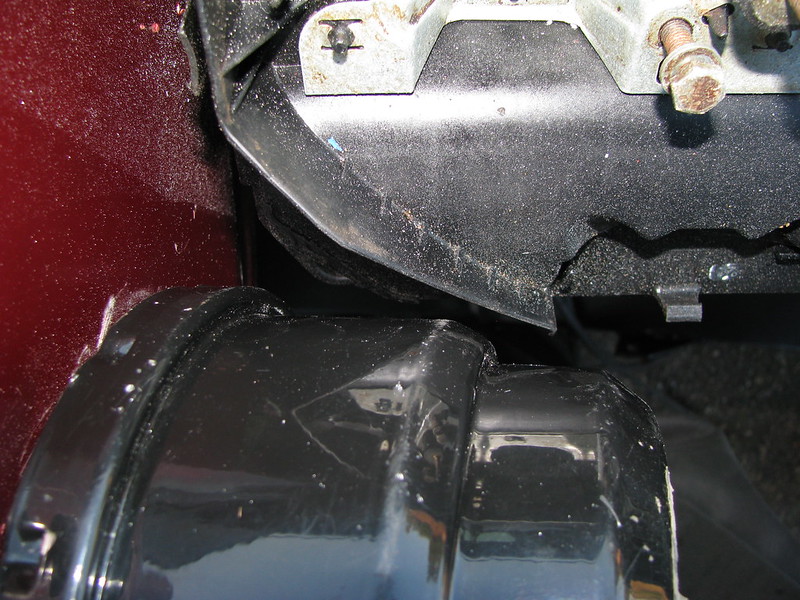 Servo/rocker cover clearance
 by
marlinpeter, on Flickr
So this is as far as I've got this week but there is a lot more checking required....
In the following picture it all looks good but there is still a lot a checking to do like the bodywork, bonnet, radiator space and steering column, etc.
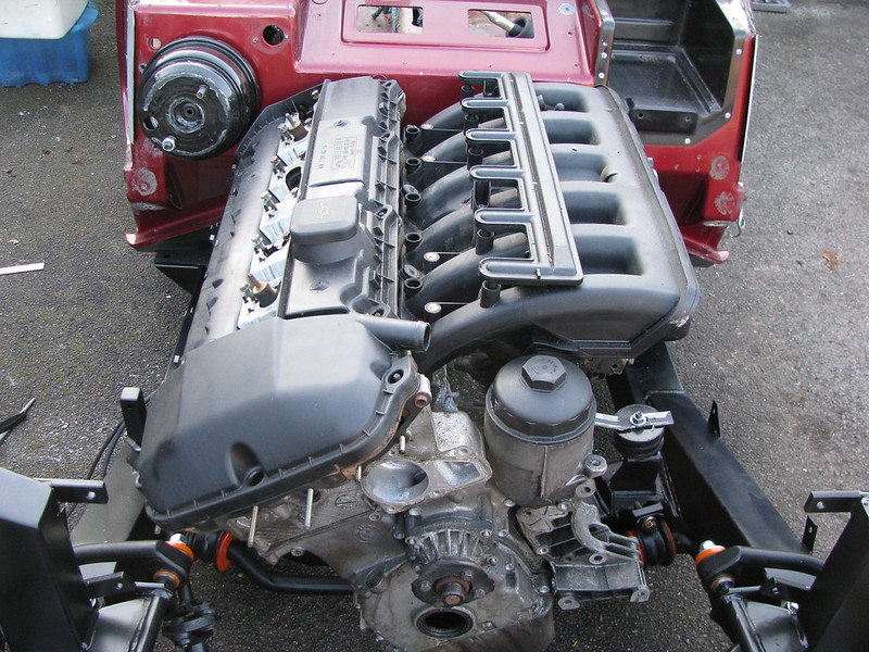 More checking required....
 by
marlinpeter, on Flickr
There is also one fundamental problem and that is the bodywork is still jacked up on 40mm blocks of wood. My original plan was to carve up the gearbox tunnel to lower the body but if I do this the servo will certainly not fit.
If I do fit this type of engine I will need to modify the chassis to lower the engine and gearbox by about 45mm.
I need to do a lot more measuring and thinking about the consequences before embarking on carving up the chassis.
Now where is that angle grinder
Yeah, but I've spent far too much time on the car this week. Pauline says that I've got OCD but I don't know what she is talking about

.....I'll add that to my list of options ...
...along with the electric power driven hood

(Do you think my wife would notice if I nicked it out of her Audi TT

eep: )
But you're right, I do seem to make things complicated for myself. I just can bring myself to putting am old Ford engine (boat anchor?) in it.
Gee thanks John, I think I'll put those on the list for when I've done everything else

Maybe as an alternative to the MBM servo is a remotely located dual circuit servo.
I've found this one manufactured by a Spanish company called Iruna brakes and sold in the UK through a couple of retailers.
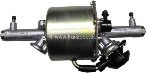 Alternative Servo option
 by
marlinpeter, on Flickr
I've found it on Google fitted in a wide variety of cars from a classic e-type jag to VW camper vans, Cobras and a 356 speedster replica.
By using a remote dual circuit servo it gives me some more options than modifying the chassis.
Anyone got any experience of these units?
...peter
Hi Sorton,
Thanks for the tip. I've had a look at those and yes, I'd need two servos for the dual circuit brakes which is a requirement for the IVA (and good sound engineering anyway

)
They look a bit bulky and have to be mounted at an angle of 25-45 degrees which adds to the space issues. (the Iruna seems to have bleed valves to get the air out)
On styling, I think you and John have watching the Sammio/Tribute threads too much
I'll be sticky rigidly to the kit design i've bought!!
.......peter