MadaboutKitcars

Build Stories are assembled automatically from a build thread's own author, in their own words and order — see all featured builds.

Royale Sabre - Take two!

By peterux · 372 updates · Sep 2012 to May 2025

Read the full original thread (with everyone's replies) in the archive →

April 2021

20 Apr 2021, 1:35pm General Update


This is the guy that gave me the inspiration and the confidence to have a go but there are lots of other 'how to' videos available.
https://youtu.be/kTM8Xy4HYAI
He uses a bit of broken tape measure to cut through the plastic but I just used a single sided razor blade.
20 Apr 2021, 7:56pm Chassis and Body


Yes, there are even video's showing that technique on YouTube but I decided the blow lamp was a safer option. :eyebrows:
22 Apr 2021, 7:32pm Mechanical Overhaul Chassis and Body

Hi Robin,
that's an interesting point you raise that could affect other builders so I had a look at the IVA manual. The closest I can find is in Section 3A requirement 10. that says......10. The fuel tank must be positioned so that in the event of a leak the fuel could not accumulate or find a path to the passenger compartment. (if fitted in a compartment there must be a drain which does not exit onto a heat source)
However, this is not an issue on the Sabre because the plate you see above that holds filler neck and cap is not sealed to the wing so any spills will just drip to the road below.
The photo below shows the filler neck before the wing was fitted, which I think explains it better.

Fuel Filler by Sabrebuilder, on Flickr

There is quite a big gap around the filler neck and the wing.
In fact, it was while I was fitting the tether that I realised I need to fit some kind of inner wheel arches to stop rain and road dirt being thrown up by the wheel all over the filler neck.

I think my car will be OK but thanks for the feedback as I'm keen to head off as many IVA issues as possible.
cheers, Peter
29 Apr 2021, 6:39pm Engine Mechanical Overhaul Chassis and Body
Just a small update to show you all what I'm working at the moment when I get the odd spare moment in the garage.

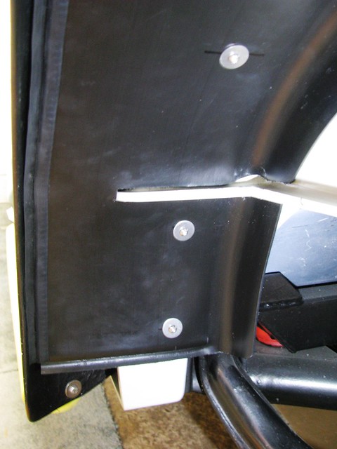
When fitting the tether to the fuel cap I realised that I needed to fit inner wheel arches or all the road muck will go all over the filler. My car wasn't fitted with anything as it was never finished. The Sabre manual says "Cut aluminium splash plates to fit between the body and the wings, behind the rear wheels. Secure to the inner wheelarch with self tapping screws. Fit edge seal to the splash plates where they contact the wings."
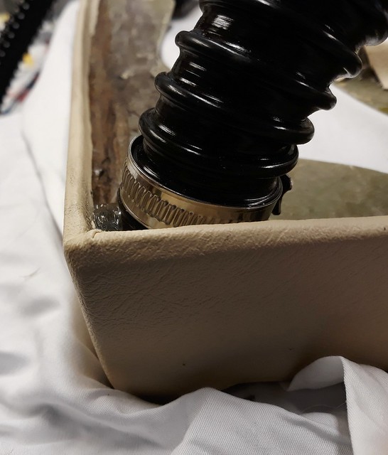
But, I thought I'd try and fabricate something a bit more professional looking so I bought these truck mudguards.
They looked about the right size and cost £36 delivered.
My plan was to cut them up to fit.

Rear inner wheel arches by Sabrebuilder, on Flickr

I first made a cardboard template and set about cutting up a mudguard. I used my jigsaw to cut the edge off and a hand wood saw to cut the slots for the Sabre's body flanges.

Inner rear wheel arch template by Sabrebuilder, on Flickr

I then offered it up and with a bit of pushing and shoving it popped in to place. I then discovered the mudguard is the exact same diameter as the Sabre's inner wheel arch. A perfect fit!

Inner rear arch top by Sabrebuilder, on Flickr

I then found on-line this edge seal that has a finned edge and I fitted that to the cut edge of the mudguard. It's good stuff but a PTA to fit to the now floppy edge of the mudguard.

Small leaf fin edge seal by Sabrebuilder, on Flickr

At the front and top I've fixed the arch in place with m6 rivnuts.

Inner rear wheel arch front by Sabrebuilder, on Flickr

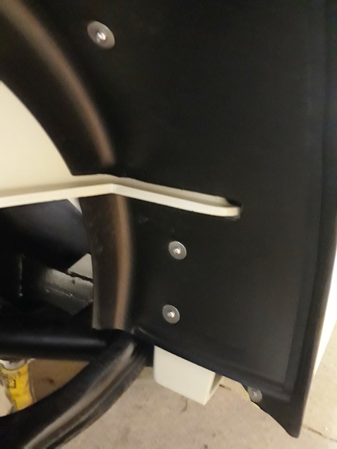
But at the back there is nothing to fix the mudguard to and it's too flexible to leave as is, so I am going to make up a bracket to support it that will be fixed behind and to the lower edge of the body tub.

Inner rear arch back by Sabrebuilder, on Flickr

It's coming together nicely and looks production.
A bit more to do and the other side, of course.

Stay safe..............peter

May 2021

8 May 2021, 8:51pm Mechanical Overhaul Chassis and Body
Work continues on fitting the inner rear wheel arches.

On the nearside, I've fabricated a support for the rear of the inner wheel arch from 8mm mild steel bar. It's fixed to the rear tub floor with saddle clips and now needs painting. The saddle clips are fixed to the bar with a dab of J-B weld to stop any movement.

Inner wheel arch stay nearside by Sabrebuilder, on Flickr

I then moved on to cutting and fitting the offside wheel arch.
It is fixed in the same way as the nearside at the front.

Inner wheel arch offide2 by Sabrebuilder, on Flickr

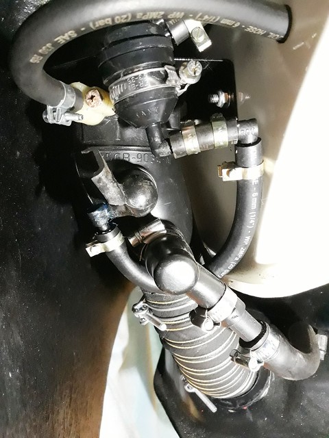
But, at the rear, I had to re-arrange one of the breather pipes to clear the inner wheel arch.

Rerouted breather pipe by Sabrebuilder, on Flickr

And the stay fixing had to be bent forward as the fuel tank was in the way at the rear. It can just be seen here below the body tub seam.

Inner wheel arch offside by Sabrebuilder, on Flickr

This shot is looking up behind the offside inner wheel arch, showing the fuel filler and breather pipes.

Inner wheel arch offside stay by Sabrebuilder, on Flickr

I just need to now remove the stays for paint and final refit.
It's taken far too much time but I'm pleased with the final result.

Stay safe...........peter
15 May 2021, 6:58pm Engine Mechanical Overhaul Chassis and Body
This week I've been tackling various small jobs. Slowly working my way through my task list.
Firstly, I painted the inner rear wheel arch stays and refitted them. So that's the inner rear wheel arches completed and ticked off my list.
Whilst I have the car raised on axle stands at the rear with the rear wheels off there were a couple of other jobs I needed to do.
One was to do with the rear brakes.
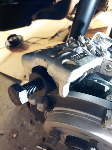
I have had issues with a 'soft' brake pedal with a feeling of some air in the system. Despite numerous attempts at bleeding the brakes I couldn't get any improvement. I found one obscure reference on the internet suggesting that air can become trapped in the Sierra rear brake calipers. I removed each rear caliper and wound the piston back with a wind back tool. I then bled the rear brakes with the tool still in place to stop the piston moving out. After some aggressive pumping of the brake pedal I did get some air out of the offside caliper. The brake feel is now much better.

Brake wind back tool by Sabrebuilder, on Flickr

I was surprised that the brake fluid bled from the rear calipers was somewhat dirty and had some suspended sediment in it. Since the only brake component that isn't new or reconditioned is the rear proportioning valve, I presume this is where the dirt has come from?

Old brake fluid by Sabrebuilder, on Flickr

Another job was to remove the rear silencer and pipework.

Rear silencer by Sabrebuilder, on Flickr

Since I first fitted this I've always had a small leak at the middle joint. I'd used some joining sleeves and exhaust clamps from Jetex that looked like these...

Exhaust shortening by Sabrebuilder, on Flickr

Despite using exhaust sealing paste these didn't work very well at all and tightening the clamps didn't resolve the issue.

I've bought some of these which seem to be a much better design as the sleeve overlaps on the inside and the clamps are wider.

Exhaust clamp by Sabrebuilder, on Flickr

They look a bit flimsy in the photo but I was pleased to find when they arrived that they are very substantial. I've not fitted them yet but hopeful they will make a much better joint and keep the IVA inspector happy.

There are a few other jobs I've started but will include those in next weeks update. Until then, stay safe.......

...........peter
23 May 2021, 8:07pm Mechanical Overhaul Chassis and Body Electrics Interior & Trim
A few more jobs off my list this week........
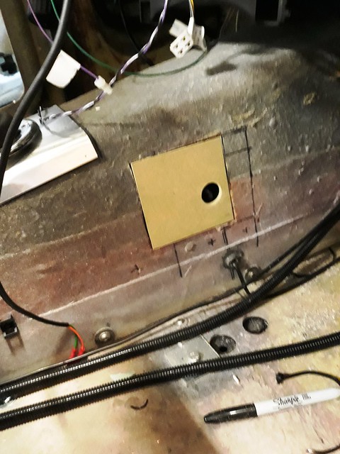
In no logical order I'll start with the speedo sensor access hatch.
I started by cutting a piece of damp resistant mdf. The round hole is to provide clearance for the sensor cable.

Hatch by Sabrebuilder, on Flickr

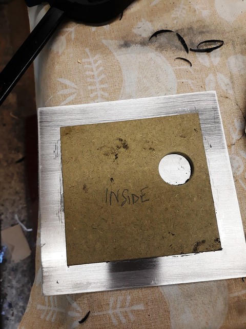
I then PU glued it to a piece of thin ali.

Hatch2 by Sabrebuilder, on Flickr

And I painted the inside to prevent moisture ingress. It was fitted with 4 self tappers and a very thin beed of RTV silicone sealer to allow removal, if necessary.

Painted hatch by Sabrebuilder, on Flickr

Another thing that needed to be addressed was that I had already fitted the window switch cables in conduit and attached them to the gearbox tunnel and I was concerned that I would end up with an unsightly bulge in the carpet.

Window switch cables by Sabrebuilder, on Flickr

I was not happy about this so I stripped out the conduits shown above. And then to reduce the thickness to a minimum, I turned the cables into a kind of 'ribbon cable' by sticking them to PVC insulation tape.

Window cables by Sabrebuilder, on Flickr

I then ran the cables in some flat PVC sleeving and glued them to the transmission tunnel with contact adhesive.

Window switch cables by Sabrebuilder, on Flickr

There are a few more wiring jobs that I need to do and a general tidy up before I refit the dashboard but I'll come back to those in future updates.

Another small job I've completed this week is fitting the front bumpers which was very straightforward.
First the bumper support bars are fitted after trimming the grommets to size.

Bumper bar and grommets by Sabrebuilder, on Flickr

The bumpers are then fitted with 16mm of washers per the RMC manual.

Front Bumper by Sabrebuilder, on Flickr
Front Bumpers by Sabrebuilder, on Flickr

So that's another couple of jobs ticked off my list.........

Stay safe, Peter

June 2021

4 Jun 2021, 6:29pm Engine Chassis and Body Electrics Interior & Trim
Not much to report over the last couple of weeks due to other priorities.
But, I've now re-fitted the rear silencer box with the new connectors. A much better fit than the previous ones and now hopefully gas tight. I just need to tidy up with a bit a paint on the exposed pipes.

New exhaust connectors by Sabrebuilder, on Flickr

I've also fitted an additional 2 way fuse box. One new fuse for the auxiliary power socket and one for the positive feed to the wiper switch which wasn't fused by the original main fuse box. The new fuse box is under the dash, just to the right of the steering column.

Aux fuse box by Sabrebuilder, on Flickr

That's all for now, stay safe.........
,,,,,,,,,,,peter
13 Jun 2021, 9:11pm Chassis and Body Interior & Trim

Thanks, indeed it is.:icon_biggrin:
I'm gradually nibbling my way through my list of jobs.......

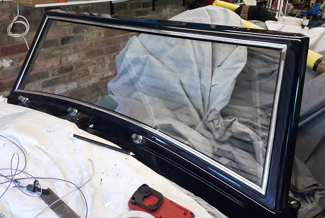
This week I fitted the windscreen. I used Sikaflex 255FC Adhesive. Bit of a messy job but I got there in the end.

Windscreen Fitted by Sabrebuilder, on Flickr

The all important marking for the IVA test.

Windscreen approval mark by Sabrebuilder, on Flickr

A few days later I fitted the 'plastic chrome' trim surround. A very time consuming job to get the mitres and lengths correct.

Windscreen surround by Sabrebuilder, on Flickr

I've also fitted the Interior Light door switches. It's practically impossible to get to the rear of the switches due to the 'A' pillar support structure so I soldered on the wires. The wire loops are to allow movement of the plunger.

Interior Light Door switches by Sabrebuilder, on Flickr

And here's one fitted....

Interior Light Door switches by Sabrebuilder, on Flickr

The lens on my phone camera has made the length of the plunger look much longer than it really is. The plungers will be trimmed to size once the doors are fitted.

So that's another two jobs done!
Stay safe.........Peter
19 Jun 2021, 8:11pm Engine Chassis and Body Electrics Interior & Trim

Thanks Jack and Kon. Some steps make a dramatic impact but others like this week when I have been doing some more mundane but equally important tasks.
I've been doing some more wiring before refitting the dashboard surround. Hopefully this will be the end of the wiring which can take a surprisingly long time for very little to show.
I been running in some extra cables like a supply to the boot for a boot light, some speaker cables and an aerial cable to the boot. The aerial will be fitted after the IVA test.
I've also been connecting up the interior light cables and running supply and illumination cables for the heater control. Plus a lot tidying up to make all the cables secure and IVA compliant.
All the unused wires to the ECU have been terminated in insulated closed end connectors and then encased in some conduit.

Unused ECU cables by Sabrebuilder, on Flickr

And then tied up under the dash.

Under dash wiring (passenger side) by Sabrebuilder, on Flickr

This required the 'head in the footwell' pose :dizzy:

Then taking a break from wiring, I made up a mounting panel for the intermittent wiper control unit. This will be later fixed at a convenient point along the lower edge of the dashboard surround.

Wiper delay panel by Sabrebuilder, on Flickr

So a few more nibbles out of the elephant and edging slowly towards the finish line :nod:

Stay safe.............peter
25 Jun 2021, 7:22pm Engine Mechanical Overhaul Chassis and Body Electrics Interior & Trim
You never stop learning things...

A little lesson on the Ford Sierra steering column that might be useful to other builders.

After what seemed like hours of sitting in the drivers seat fiddly about with wiring to make it all neat and secure I noticed that I had a small amount of play in my steering column around the lower of the two upper column bearings (labelled C).
I know the IVA inspectors are hot on any play in steering components so decided that I had better investigate now before I refitted all the dashboard. I had theorised in my head that the lower bearing might be worn or the thrust washer might be missing.
Here's a useful Ford diagram I found on line....

Ford Sierra Steering column by Sabrebuilder, on Flickr


So I removed the upper outer column which is just two bolts and I immediately saw the problem. The lower thrust washer (labelled B) was the wrong way round. :eusa_naughty:
I swapped it over, bolted it back up and fitted the steering wheel. Problem gone completely with no perceptual play. I must have assembled it incorrectly about 8 years ago when I cleaned and painted the column.
I feel a bit of a dummy for doing this but really glad I found it now before the IVA test!!
More progress to report tomorrow....
Stay safe, Peter
26 Jun 2021, 8:19pm Chassis and Body Electrics Interior & Trim
Sometime the simplest jobs....

Thanks to Jack and Mick for your kind comments on last weeks update.
-----------------------------------------------------------------------
I'm trying to complete two tasks per week and this weeks tasks looked like some easy wins.
My list simply said "recover windscreen trim and fit Interior light and mirror" what could be simpler?
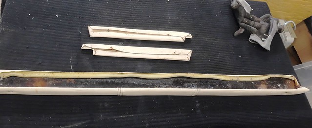
First, I had to push the car out of my garage to access the loft above and the car is certainly getting heavier with so much now fitted. Luckily, the windscreen trim pieces were in the box that I packed them in 8 years ago! And on first sight didn't look to bad.....

Windscreen trim by Sabrebuilder, on Flickr

But when I started to strip of the old covering I found the rain had soaked into the foam backing and rusted the metal former.....

Windscreen trim by Sabrebuilder, on Flickr

So I first stripped of any remaining paint and glue with some paint stripper. I then coated it in some de-rust gel to remove most of the rust and after that sanded it smooth. A coat of rust converter and then some new black paint restored it back to almost new condition.
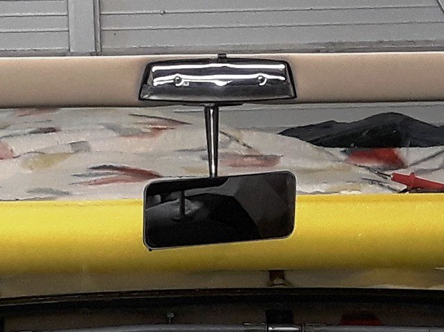
Then it was recovered with some new foam and cream vinyl. I then trail fitted the interior light and mirror before refitting to the car.

Windscreen trim by Sabrebuilder, on Flickr

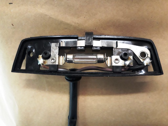
Having connected up the interior light I decided to test it by connecting the battery. As I reconnected the battery there was a spark and a small pop sound. Hmmmmmmm :doh:
I checked the main fuse panel and sure enough Fuse 2 had blown which is the supply to the courtesy lights. The interior light has three connections Earth, Perm supply and switch supply. The colours of the wires match the Sabre loom so I just connected them up.

Interior light by Sabrebuilder, on Flickr

It has three wires because like most interior lights it has a little slide switch which over rides the door switches. After a bit of head scratching and studying the switch I realised it was designed for a 'switched earth' circuit but the Sabre loom is a 'switched live' circuit. (This was my scribble on the bench)

Interior light connections by Sabrebuilder, on Flickr

The simple solution was to swap to 'switched live' by swapping the purple (permeant supply) and the black (earth) wires. The wires are soldered to the light fitting so quite easy to de-solder and swap the wires over.

Finally, I could screw it all back in position....

Interior light and mirror by Sabrebuilder, on Flickr

So I got my tasks done this week but it took much more time than expected but it's all part of the fun :icon_mrgreen:

Until next week, stay safe, Peter

July 2021

13 Jul 2021, 9:01pm Engine Mechanical Overhaul Chassis and Body
Doors, locks and latches.....

For once my lack of updates is because I've been very busy in my garage. I finally decided to tackle the re-assembly of the doors. The original builder had made a start on the doors but I don't think they were ever finished as the locks didn't work and the electric windows weren't wired up.
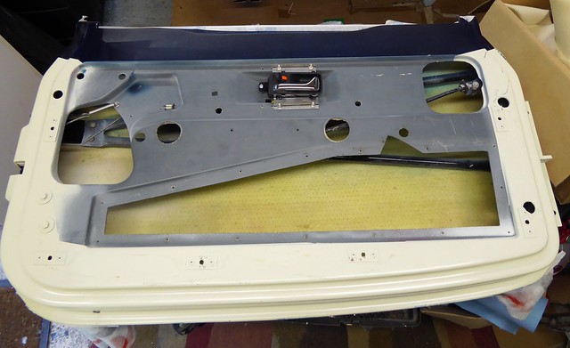
For those of you not familiar with the Royale Sabre, the doors are a complex GRP moulding with an internal steel support frame. Working on the door locks is like key hole surgery and a pair of very long nose pliers are essential.

Drivers door by Sabrebuilder, on Flickr

One of the benefits of my build being over an extended period :eyebrows:, I've been able to accumulate new latches, exterior handles and internal handles. The doors are designed to use either Ford Sierra or Ford Granada locks and handles. I'm using Sierra latches and Granada handles as these are nice chrome versions of the cheaper black plastic Sierra ones. It's a bit of an adventure as the build manual leaves little detail on how the latches and handles should be assembled.
The locks are fiendishly complicated to understand how they operate and I hoped it would become clearer once they are connected.

Drivers door lock1 by Sabrebuilder, on Flickr

The tab on the left with the red clip is for the external key lock. The other left tab with the yellow clip is for the external handle. The tabs on the right are for the internal handle and lock. Ford designed them with a primitive central locking system but I have decided not to use this for a number of reasons and I figured that on a two door car it wasn't really a problem.
I manged to source new locks from Germany.

Drivers door lock2 by Sabrebuilder, on Flickr

The Royale build manual advises that it's not possible to use the original Ford lock barrels as the GRP doors are thicker than the Sierra steel door skins. The ones that came fitted to the car are very rusty so I bought these off a stall at Stoneleigh. The tab is far too large and had to be modified.

Lock barrel 2 by Sabrebuilder, on Flickr

The Ford lock 'red tab' has a total travel of only18mm so I had to create something that translates 180 degree rotation to a 18mm travel. This is the third option that I came up with and seems to work. The small bush in the centre is welded to the tab but is a bit rough as I had the welder turned up too high. The washers at the base are Araldited on just to hold them in place while the 5mm countersunk screw is tightened.

Drivers door lock adapter by Sabrebuilder, on Flickr

With the key lock and adapter in place I then had to bend up an operating rod to connect the two. Here it is shown in the locked and unlocked position.
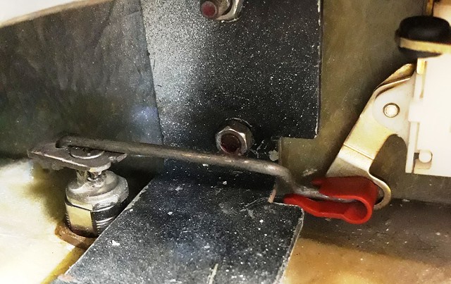
Drivers door lock rod 2 by Sabrebuilder, on FlickrDrivers door lock rod 1 by Sabrebuilder, on Flickr
Rotate the key and it is in the locked position. The metal bar in the middle is part of the steel internal door frame. Bending and shaping the rods is a very tedious and frustrating job with much cursing.

Next, I fitted the exterior handle....

Exterior Locks by Sabrebuilder, on Flickr
And then bend up another rod to connect the extrior handle to the latch mechanism. The original Ford rod turned out to be the right length but the wrong shape so with more bending and more cursing...

Outside handle actuator rod 1 by Sabrebuilder, on Flickr
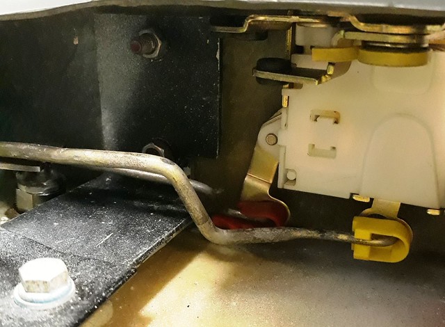
Outside handle actuator rod 2 by Sabrebuilder, on Flickr
So now I had an external key barrel lock and handle that seemed to work so I moved on the fit the interior handle....
The original builder had used the Sierra handles but I wanted to use Granada chrome handles.
Interior door handles by Sabrebuilder, on Flickr

It soon became obvious that I need to fit the door card to get the position and height of these handles correct. Here's the GRP door card being fitted to align the interior door handle.

Door card by Sabrebuilder, on Flickr

I've fixed the interior door handle with these two strips of galvanised steel.

Interior handle fixing 1 by Sabrebuilder, on Flickr

And then make up another actuating rod from the handle to the latch....
NOTE: the following fitting is incorrect. Please see Post #538 below for the correct fitting.
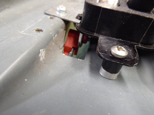
Interior handle actuator rod by Sabrebuilder, on Flickr
Which had to be supported half way along with one of the original Ford clips.

Interior handle actuator rod by Sabrebuilder, on Flickr

At this point I decided not to fit the actuator rod for the internal lock as with a soft top car this would be a security risk. It would be easy to put a wire or stick between the top and window and flick the lock off.
But now I was stuck as the logic of the Ford latch mechanism didn't work.
To cut a long story short I found adding a spring in place of the interior lock appears to work.
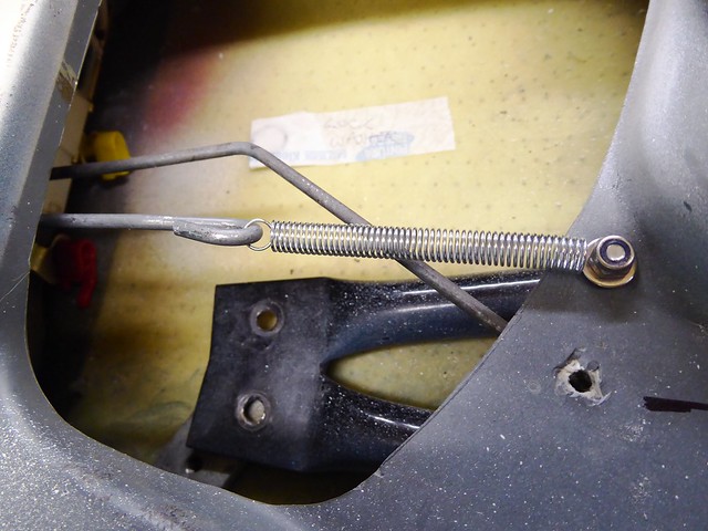
Interior handle actuator rod by Sabrebuilder, on Flickr

The spring allows the fourth operating leaver on the latch to be moved when unlocking with the key and pulls it back to the locked position when the key is moved to the locked position.
Difficult to put it into words but it appears to work.

This has to have been the most frustrating part of the build but I feel I'm nearly there.
Of course, I've still got to tackle the electric windows but I may do the locks on the passenger door while I can remember how I did it!

So until the next update, stay safe........

Peter
15 Jul 2021, 7:49pm Chassis and Body


Yes, it surely is. It doesn't look exactly like any Sierra doors I've seen on line but I'm guessing that this must have been the starting point. Perhaps they modified a steel door and then took a mould?
As you say, the amount of work creating all the drawings, jigs, tooling and moulds for the Sabre must have been a huge project. John Barlow (the designer) must have envisaged selling a much higher number of kits than the 150 that were made. Even the door cards are a custom moulded GRP part.
25 Jul 2021, 7:51pm Engine Chassis and Body Interior & Trim
Not a huge amount of progress since my last update but I have now fitted the grab handle to the drivers door.
The grab handles are screwed to a threaded plate that sits behind the door's inner skin. But the grab handles and securing plates were missing from my car, presumably lost somewhere along the way?

As the grab handle support plates were missing , I made some up from 4x35mm bar simply because this is what I had in my stash. The outer two holes are threaded to take 5mm fixing screws and the two inner holes are to fix the plate to the door inner door skin.

Grab handle and support bar by Sabrebuilder, on Flickr

You then fix the door trim panel in place and drill the holes through the trim panel and inner door skin to get the holes aligned.
The support plate is then pop rivetted to the inside of the inner door panel. The pop rivets are just to hold the plate in place until the fixing screws are done up. A very neat solution.

Grab handle fixing by Sabrebuilder, on Flickr

The keen eyed might notice that the self tapping screws I used to fix the inner handle have now been replaced with M4 nuts and bolts. The original builder had used self tappers but the RMC build manual says to use nuts and bolts and who am I to argue with John Barlow!

I've started fitting the locks to the passenger door now, so no updates for a while...

Until then, stay safe,

Peter
31 Jul 2021, 9:09pm Engine Chassis and Body Electrics Interior & Trim
Taking a break from working on the door locks and latches I decided to refit the dashboard surround which I haven't done since recovering it.
I then discovered that the heater demist pipes fouled against the body tub just below the windscreen. A quick check in the build manual confirmed that these should have been fixed at 45 degrees.
I had to remove them and refit correctly like this...

Demister vent connection hose by Sabrebuilder, on Flickr

Then I was able to refit the surround and dashboard....

Dashboard and surround by Sabrebuilder, on Flickr

And just for future reference this is the surround's centre mounting fixing.

Dashboard surround support fixing by Sabrebuilder, on Flickr

Once the steering column controls wiring is securred I can then test it all again :whistle:

Until then, stay safe.........

Peter
August 2021

23 Aug 2021, 8:43am Engine Chassis and Body Interior & Trim
Not much progress in August due to grandchildren school holidays, days out and a short holiday.

But I did have some garage time yesterday and fitted and tested the windscreen wipers. The dashboard and steering column switches are all back in so I was able to give the engine a good run and I was pleased to find it started first try.
When I first installed the wiper system I had no windscreen so was not able to fit and test the arms and blades.

I started with the usual safe test with drinking straws to check the sweep angles looked ok.
(You will have to click on the picture to see the video clip)

Windscreen wipers 2 by Sabrebuilder, on Flickr


That looked okay so I proceeded to fit the arms and blades. The arms need to be shortened and the crank angle tweaked to get the blades close to the windscreen lower edge. I started with the far left wiper arm and worked my way across.

Wndscreen wipers 1 by Sabrebuilder, on Flickr

Despite all the rain yesterday I was testing inside with a bottle spray so the real test will be in the real rain :-)

Progress will be slow over the next few weeks so that's all for now,
stay safe,

Peter

September 2021

12 Sep 2021, 8:53pm Engine Chassis and Body Electrics Interior & Trim
Okay, so here's a quick update of what I've been up to in my garage....

Apart from the pull handle fixing, I've finished the locks on the passenger door.
(Glad that's over as it's the fiddliest of jobs)

Passenger door by Sabrebuilder, on Flickr

The cut out for the passenger door latch had been poorly cut so I had to fill it, reshape it and paint it before installing the Ford latch. I had sourced some brand new Ford fixing screws but they were too short due to the thickness of the GRP. But I found some yellow passivated Torx screws on ebay that look professional. I also bought some matching yellow passivated bolts for the door crash protection bars fixing.

Door latch by Sabrebuilder, on Flickr

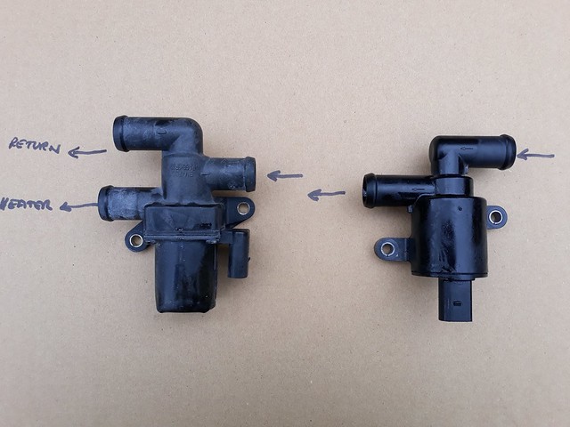
When I first installed the engine I used a two port heater valve between the engine and the Sierra heater matrix.
It dawned on me one day that this was a potentially a big mistake as it means the coolant doesn't circulate through the BMW M52 cylinder head when the heater valve is closed. Whilst looking for a solution on ebay I came across a VW/Audi three port valve that was similar to the two port valve I used initially.

Heater valve comparison by Sabrebuilder, on Flickr

Luckily, the new three port valve is almost identical in size to the original, the same mounting hole dimensions and has the same electrical connector, making it a relative easy swap.

New heater two way valve by Sabrebuilder, on Flickr

Here's the new valve installed. The main work was re-routing the hoses and adding an additional return flow hose for when the valve is shut.

New two way valve installed by Sabrebuilder, on Flickr

Hose work complete. The air vent had to be repositioned due to lack of space.

New heater valve installation by Sabrebuilder, on Flickr

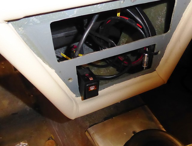
I've wired up this temporary switch to control the heater control valve. Testing confirmed that I can now switch the coolant on and off through the heater matrix.

Temporary heater control switch by Sabrebuilder, on Flickr

That's all for now........

....peter
28 Sep 2021, 4:54pm Chassis and Body Interior & Trim
I'm now back working on the doors again......
The next job on the list is to refit the door windows and their electric winding mechanisms.
I started by refitting the window channels and some new velvet covered rubber channel runners. I then trial fitted the window glass and quickly discovered that it clashed with interior handle control rod. It was then that I realised the control rod has to be fitted above the inner door skin (i.e. between the inner door skin and the door trim panel). At first this looked like a lot of re-work but I manged to rebend the existing rod and cut a new slot for the supporting clip.
This is how it is supposed to be fitted....

Internal handle control rod by Sabrebuilder, on Flickr

A couple of hours of knuckle scrapping and it was re-fitted correctly.

Also, potentially fouling on the window glass was the nut and bolt I fitted to stop the lateral movement of the handle. The new arrangement consists of an aluminium strip bolted to the handle and then fixed to the inner skin well away from the window glass.

Internal handle fixing by Sabrebuilder, on Flickr

The window glass now slides up and down smoothly, without any issues.

I'm now working on fitting the weather strip but I also need to fit the chrome strip and the wing mirror as you can't get to the fixing nuts of these once the glass is in place.

Until next time, stay safe..........

............peter

October 2021

8 Oct 2021, 7:03pm Mechanical Overhaul Chassis and Body Interior & Trim
Work continues on my the doors for my Royale Sabre.....

The original chrome decorative trims are badly corroded and didn't shine up when polished with chrome polish.
When I bought the unfinished Sabre it came with an incomplete set of new trims. I have decided to use the new trims on the doors but they had the remains of the welded on connections for the chrome plating process. It took me a good few hours with a 'dremel' type grinding wheel and a set of needle files to remove all the debris.

Door Chrome decorative trim by Sabrebuilder, on Flickr

Door Chrome decorative trim by Sabrebuilder, on Flickr

The original chrome strips had fixing studs welded or maybe braised to the strip.
The new strips have a slot but no fixings in the box.
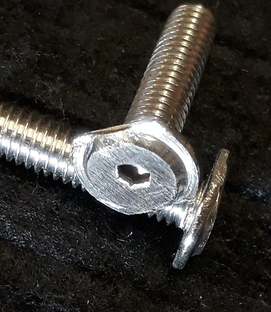
Whilst looking for a solution, I found that if I shaved the top off a m4 button head screw it would slide into the slot but would rotate when you tried to tighten them. So I got some flange head stainless steel screws and by shaving the head and then grinding off two parallel edges these homemade fixings slide into the slot but don't rotate when tightened. It took me about an hour to make 8 fixings.

Chrome trim fixing by Sabrebuilder, on Flickr

Here's the first chrome strip now fixed in place.....

Door Chrome decorative trim by Sabrebuilder, on Flickr

Moving on, I next tackled the mounting of the 'wing' mirrors.
I'm using Tex 'e' approved wing mirrors to avoid any issues at the IVA test. I had to profile the back of plinth to match the curvature of the door.
Nothing seems simple on these doors!

Wing mirror mounting plinth by Sabrebuilder, on Flickr

I refitted the window channels and trimmed the new flocked rubber window channels to the door top profile. Filing out the top of the doors to match the shape of the channels is another tedious time consuming process.
I then moved on to fitting the window glass weather strip....
The weatherstrip was cut to size, trimmed at the ends to fit over the channels and then fixed to the door with small self tapping screws along it's edge. (poor photo warning..)

Door window weatherstrip by Sabrebuilder, on Flickr

I'm now moving on to re-installing the electric lift mechanism and windows....
Until next update, stay safe........

...peter