MadaboutKitcars

Build Stories are assembled automatically from a build thread's own author, in their own words and order — see all featured builds.

Royale Sabre - Take two!

By peterux · 372 updates · Sep 2012 to May 2025

Read the full original thread (with everyone's replies) in the archive →

July 2019

18 Jul 2019, 7:53pm Engine Mechanical Overhaul Chassis and Body Electrics Interior & Trim
Mid-week update...


I've now completed the fuel filler and tank breathing so I thought I'd add an update here....

To fit the fuel filler on a Sabre you take the standard Ford Granada filler tube, cut it in two and extended it with a piece of flexible fuel filler hose. I used ATL fuel filler hose from Demon-Tweeks. The top part of the filler is fixed with a RMC supplied bracket. I was lucky to find a brand new filler cap as the rubber seal on the old one had perished. A fuel cap tether will be added after the rear wing is in place so that I can get the right length.

Fuel Filler by Sabrebuilder, on Flickr

The Ford filler tube has a somewhat complex set of breather connections. One is a condensation trap that is connected to the top of the tank via a very small tube. another is the breather hose which has a ball valve that shuts off the connection if the car is rolled over in an accident and the third 12mm connection is to allow air out of the tank when filling up. Well I think that's the theory? The hoses will be sealed where they enter the bodywork once I'm happy it is finalised.

Fuel Filler by Sabrebuilder, on Flickr
(sorry about the cluttered background in these shots, not my best photo's)

These are the breather hoses in the boot space.

Breather hoses by Sabrebuilder, on Flickr

So now that the filler is ready for it's first fill up with some fresh petrol, I moved back to do some more wiring....

I continued with installing the rear section of the loom.
(warning: more boring pictures of wires!)

The rear loom starts off behind the dashboard, runs down the drivers 'A post' and then along inside the drivers side sill. It emerges here at the 'B post'.
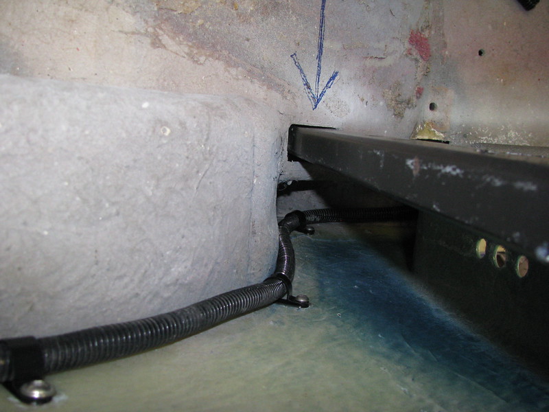
Rear Loom by Sabrebuilder, on Flickr

The loom then runs over the driver's side rear wheel arch. There is a branch off that goes to the nearside rear lights.

Rear Loom by Sabrebuilder, on Flickr

The in-tank fuel pump and fuel level sender could then terminated.

Fuel pump and sender. by Sabrebuilder, on Flickr

I've got to finish off routing the loom to the nearside rear lights. I then have to connect up the handbrake switch, the low brake fluid reservoir switch, the foot brake switch, the radiator fan and thermo switch and, of course, the whole dashboard (!) to complete the wiring for the engine start.
Front and back lighting and power door locks and windows wiring will follow the bodywork re-assembly.

More next week........

...peter
19 Jul 2019, 9:50pm General Update
Thanks Paul, slowly inching forward. :icon_smile:

August 2019

4 Aug 2019, 9:07pm Engine Chassis and Body Electrics Interior & Trim
Progress report....

Here's a few pictures of some of the things I've been doing in the garage of the last few weeks.

So in no particular logical order....

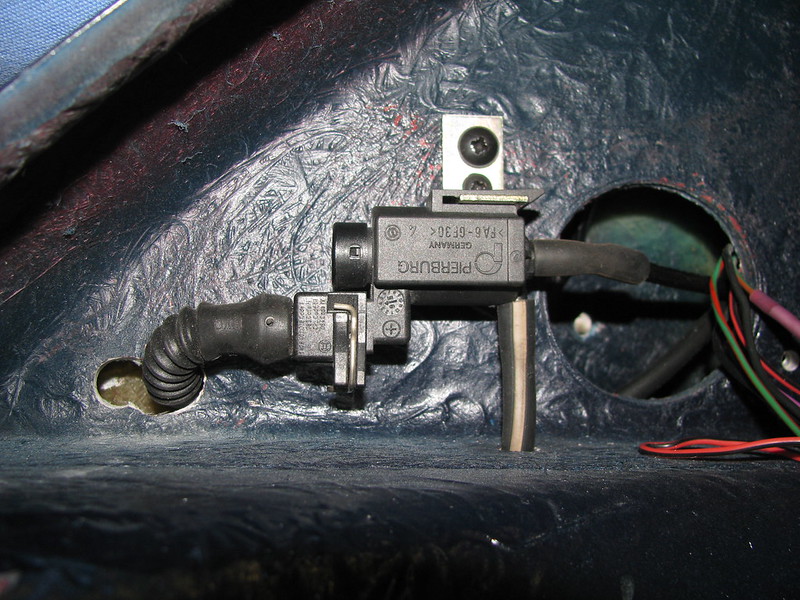
I finished running the cables and vacuum hose for the exhaust flap actuator.

Exhaust Flap solenoid by Sabrebuilder, on Flickr

The exhaust flap vacuum is controlled by a small valve controlled by the ECU. I've mounted the valve in the rear corner of the boot just behind the rear lights. It then runs to the rear silencer box here...

Exhaust Flap vacuum hose by Sabrebuilder, on Flickr

I've also fitted a cheap fuel filter on the end of the fuel tank breather to prevent any dirt or dust getting back into the tank. It is probably not required but it didn't seemed right to leave the end of the hose open.

Fuel tank breather by Sabrebuilder, on Flickr

Taking another break from the wiring, I cleaned and painted the canshaft cover bolts and then refitted the camshaft cover with a new gasket and installed the coils' connection loom.

Camshaft Cover by Sabrebuilder, on Flickr

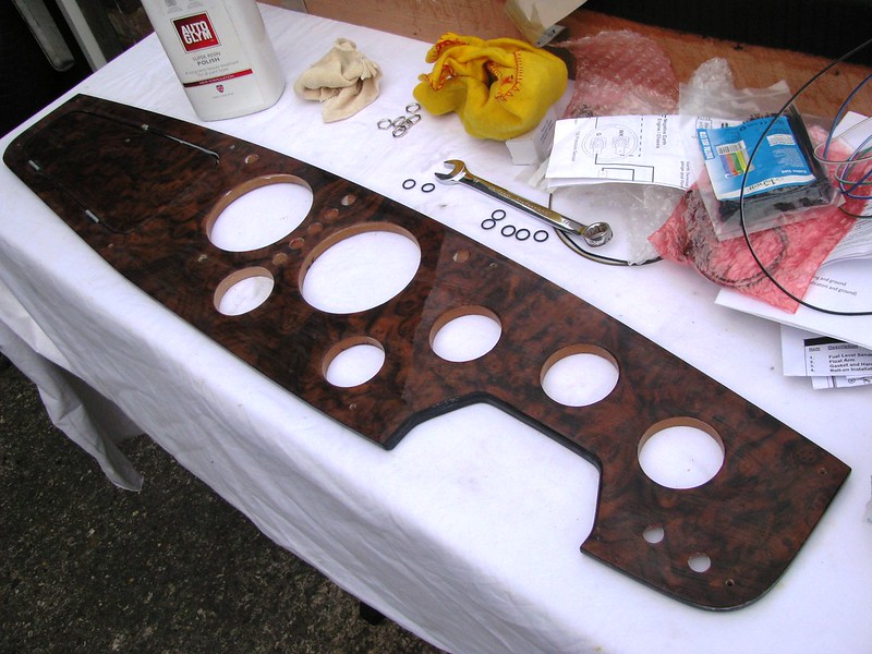
Then back to the wiring so I've made a start on the final assembly of the dashboard. I had one more hole to drill for the Speedo setting push button. I then gave it a clean followed by three coats of Autoglym resin polish to protect the surface and make it easier to keep clean.

Dashboard by Sabrebuilder, on Flickr

I then prepared the warning lights. They came with screw terminals which seemed to have a tendency to work loose so I soldered the wires to the terminals.

Dash warning lamps by Sabrebuilder, on Flickr

I then fixed them to the dash. Keeping the legends straight whilst tightening the back nuts was quite challenging,:eusa_whistle:

Dash warning lamps by Sabrebuilder, on Flickr

Because of the thickness of the dashboard there wasn't space to use a lock washer under the nuts so after tightening as much as I could, I then ran a bead of super glue into the threads and around the nuts to stop them loosening through vibration.

Dash warning lamps by Sabrebuilder, on Flickr

A few weeks ago I had about 40 tasks on my list of things to complete before I can restart my engine.
I'm now down to 29 tasks so making progress!!

Another busy week planned next week with the grandchildren but I hope to make some more progress on the dashboard in my spare time.


....peter
10 Aug 2019, 9:31am General Update


Thanks for the feedback :biggrin1:
13 Aug 2019, 8:37pm Electrics Interior & Trim
Dashing along.........

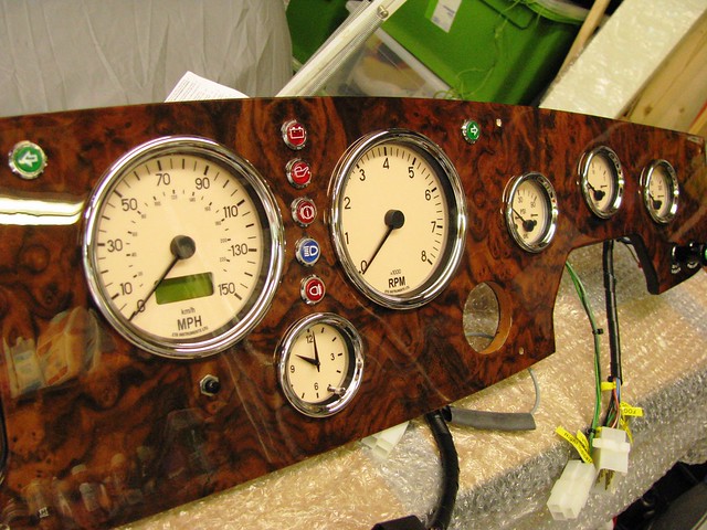
I've now mounted the instruments to the burr walnut veneered dashboard. I bought ETB dials with magnolia coloured faces. These were a little darker than I expected but they match the tone of the dashboard very nicely. I'm very pleased with the way they look......

Dashboard by Sabrebuilder, on Flickr

(I found it very tricky to photograph as it is so shiny :lol:)

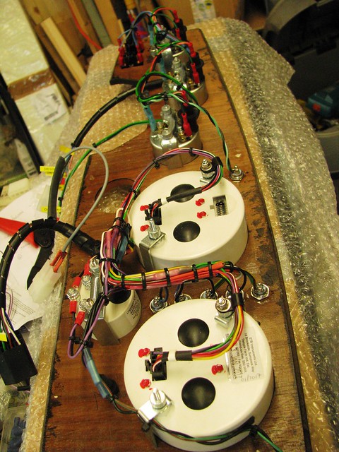
Then after a marathon two day wiring session, I've wired them all up.

Dashboard by Sabrebuilder, on Flickr

And for those interested in the detail here are a couple of close up shots.

Dashboard by Sabrebuilder, on Flickr

Dashboard by Sabrebuilder, on Flickr

I've not tested it yet but I'm very happy with progress this week:tea:


...peter
21 Aug 2019, 7:25pm Engine Mechanical Overhaul Electrics Interior & Trim
A few more tasks....

Molleur, Amir and Pheaton......Many thanks for all the kind remarks.

---------------------------------------------------------------------------

Moving on........ I've manged to complete some more items on my task list.

First up brakes. I had refitted the the brake master cylinder and filled the system with brake fluid a few weeks ago and I was very disappointed to immediately find brake fluid dripping on the garage floor.
One joint was a simple mistake as it was only hand tight and I had just forgotten to tighten it up. The second one took a closer inspection where I found the pipe was not properly aligned with the fitting meaning the flared pipe was not sealing correctly.
With both of these fixed I was able to bleed the whole system. I'm not yet 100% happy that all the air is out but I'll leave it a few weeks to settle and then bleed it again. I also need to crawl around under the car to fully check for any other leaks.

I was then able to fit the brake fluid level switch cable.

Brake fluid level switch by Sabrebuilder, on Flickr

The brake fluid level switch is wired in with the handbrake switch. I have no idea why the Ford designers made the connector so large?

I then had to route the cable to the handbrake switch so it made sense to route the window switch cables at the same time.

Window switch cables by Sabrebuilder, on Flickr

The electric window switches will be mounted on the gearbox tunnel. These cables will be hidden under the carpets.

I had to spend a while on my back with my head in the footwell to cable tie these cables. I just hope the IVA man appreciates my efforts.

Cabling by Sabrebuilder, on Flickr

I then cleaned up and greased the handbrake mechanism and then used a 5mm thick strip of foam rubber to seal it to the propshaft tunnel. The gaps left over from when I modified the gearbox and propshaft tunnels were filled with some small pieces of water resistant mdf.

Handbrake refitted by Sabrebuilder, on Flickr

The handbrake was connected to cable 'half-moon' and liberally coated with white grease.

Handbrake cable by Sabrebuilder, on Flickr

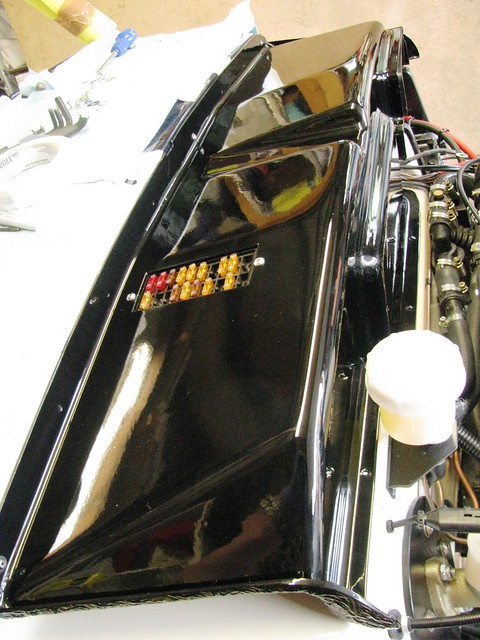
With most of the engine related wiring now complete I then moved back to the engine bay and fitting the scuttle cover. My first attempt at re-fitting the scuttle cover failed when I discovered it fouled on the wiper motor. I hadn't realised how critical the position of the motor is. In the end it took three attempts to get the right position. Very frustrating :frusty:

Wiper motor position by Sabrebuilder, on Flickr

With the motor moved I could then temporarily fit the cover.

Scuttle cover by Sabrebuilder, on Flickr

I then gave it three coats of Autoglym polish before covering it with paper towel to prevent damage.

Scuttle cover by Sabrebuilder, on Flickr

So some good progress this week and next I'll be making up some brackets to mount the cooling system header tank.

...peter
28 Aug 2019, 8:07pm Engine Mechanical Overhaul Chassis and Body Interior & Trim
A small setback....

Pheaton, Amir and Kon thanks for the 'likes'.

--------------------------------------------------------------

I had a small setback this week.........
I opened the garage door to find a small puddle of power steering fluid on the concrete. My recon steering rack is leaking fluid. :eusa_doh:
I assume the seals have dried out and shrunk or possibly the seals have been damaged by turning the steering without any fluid. With hindsight (that wonderful thing!) I think I should have found a way of keeping the rack full of fluid.

Steering rack leak by Sabrebuilder, on Flickr

The leak seems to be coming from this 'dust' cap.

Steering rack leak by Sabrebuilder, on Flickr

I have another used rack that I may try or get recon'd.

Steering rack leak by Sabrebuilder, on Flickr

But I have decided to leave it for now and worry about it nearer to the IVA test.

So moving on with some more progress....

My plan was to mount the cooling system header tank something like this.....

Coolant Header Tank by Sabrebuilder, on Flickr

But that was two years ago and before I had fully worked out the heater hoses and the outlet clashed directly with the heater control valve.

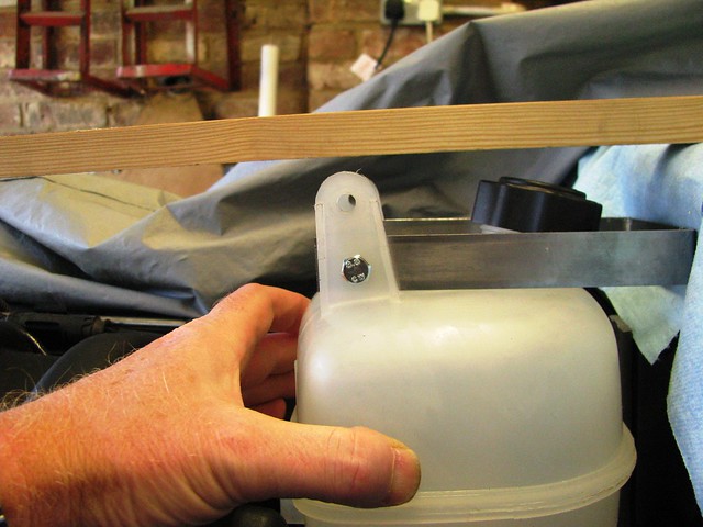
But I found that rotating the tank through 180 degrees meant the outlet cleared the heater hoses but made making the mounting brackets a bit more challenging. Here I am checking the tank clears the bonnet represented by the piece of wood.

Header Tank by Sabrebuilder, on Flickr

Here is the top bracket finished and bolted to the scuttle cover. I put a strengthening plate on the inside of the cover.

Header Tank by Sabrebuilder, on Flickr

The lower bracket was made from 4mm thick steel strip to support the weight of the tank and coolant. Again, a support plate was mounted on the inside of the cover to strengthen it.

Header Tank by Sabrebuilder, on Flickr

And here it is finished.

Header Tank by Sabrebuilder, on Flickr

Next it was on to the Idle Control Valve (ICV) hose....

Because the inlet bellows to the throttle body is upside down (compared to the way BMW designed it) I needed to find a way of feeding the idle air from the inlet bellows to the ICV that is mounted under the inlet manifold. I used silicone hose and Mikalor wire hose clamps. These are much cheaper than Jubilee clips, neater and so much faster to install.

ICV hose by Sabrebuilder, on Flickr

The hose drops down the gap between the throttle body bellows and the inlet manifold and then through a 180 degree elbow up into the ICV.

ICV hose by Sabrebuilder, on Flickr

It was then on to the brake servo vacuum hose with a new length of pucker BMW hose.

Brake Servo Vacuum hose by Sabrebuilder, on Flickr

So that's the progress this week and I'll leave you with this photo.....

August 2019 view by Sabrebuilder, on Flickr

To check the clearance of the header tank I temporarily installed the radiator cover.
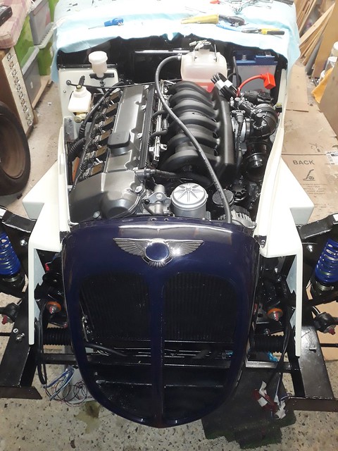
I couldn't resist taking this shot and doesn't that BMW straight 6 engine suit the Sabre!:icon_razz:

Next week I shall be working on mounting the radiator......


....peter

September 2019

11 Sep 2019, 7:40pm Engine Mechanical Overhaul Chassis and Body Electrics
Not a lot.....

I've not had much time over the last two weeks so just a few tasks completed.

I've finished the servo vaccum hose with a reducing elbow.

Servo Vacuum Hose by Sabrebuilder, on Flickr

All hoses are supported with cable ties separated by small off cuts of fuel hose.

I could then complete the Mass Air Flow meter and air filter final installation. One more hose clip (on order) to be added and MAF cable needs to be properly secured.

MAF and Air Filter by Sabrebuilder, on Flickr

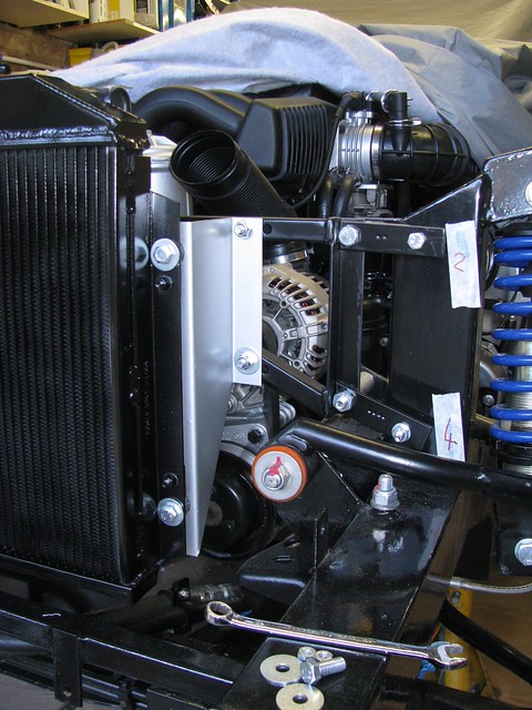
Then, after de-rusting and painting, I've refitted the radiator support frame.

Radiator Frame by Sabrebuilder, on Flickr

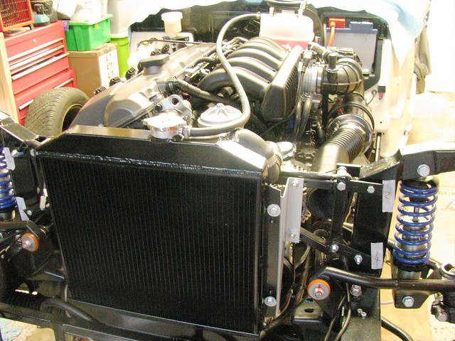
And then refitted the radiator......

Radiator by Sabrebuilder, on Flickr

I didn't want the ali radiator to show through the radiator grill so I gave a quick thin coat of VHT paint. It needs a second coat before final fixing, but I ran out of paint.
Next tasks include fitting the radiator hoses and wiring up the radiator fan, etc.

Well that's all for now........

............peter

October 2019

14 Oct 2019, 7:39pm Engine Electrics Interior & Trim
Cooling and powering on...

Sorry for the lack of updates but holidays and garden clearance have taken priority over the last few weeks but all this rain recently means I have been inside the garage for the odd hour here and there.

I'm getting ever closer to restarting my engine.
I've completed the cooling system and filled it with G13 coolant.

Cooling System by Sabrebuilder, on Flickr

The radiator has been fitted with a valveless cap and the hose between the radiator and the header tank is temporary until I have worked out its best routing.

Here's the top hose. I'm using the original BMW sensor to trigger the electric radiator fan.

Radiator Fan Sensor by Sabrebuilder, on Flickr

For the record here's the bottom hose.

Bottom Radiator hose by Sabrebuilder, on Flickr

Upper part is BMW and lower part is Ford Escort.

Header Tank by Sabrebuilder, on Flickr

The hose coiled up on top of the header tank is the windscreen washer hose.

I've also nearly completed the air intake. Just need to add a duct flange at the front.

Air Intake by Sabrebuilder, on Flickr

I've also finished 99% of the wiring loom so I was able to connect up the battery and install the dashboard.

Dashboard by Sabrebuilder, on Flickr

Not sure yet about the colour of the surround it will depend on the interior trimming.

And powered up it looks like this...

Dashboard powered up by Sabrebuilder, on Flickr

One fault found, so far. Oil pressure light was wired to ground instead of +12v.

I'm now moving on to the preparation for the engine start. I've put a new oil filter in and filled the engine with fresh oil. After removing the old spark plugs I cranked the engine to get some oil pressure.

Next job will be to put some fuel in the tank and prime the fuel pumps.
I'll then be ready to install the coil packs and wiring and see if it will start!!

I hope to have her running before we leave the EU :flypig::flypig:


....peter
19 Oct 2019, 7:48pm Engine Mechanical Overhaul Chassis and Body Electrics
Not a good week....

Sometimes things just don't go well......

It started off OK and I was looking forward to re-starting my engine. Before that there was just a few things to complete.

I made this cover from aluminium mesh to stop things falling into the alternator cooling duct.

Alternator air duct cover by Sabrebuilder, on Flickr

Also, since fibreglass is flammable I have fitted a heatshield above the catalytic converter. I used Cirrus GIIIX 3 Layer Heat Shield from Demon Tweeks. I mounted it with a 10mm gap from the body to allow air to flow both sides of the shield.

Exhaust Heat Shield by Sabrebuilder, on Flickr

But then things turned bad.....

Whilst under the car fitting the exhaust heatshield I noticed a brake fluid leak from the rear brake deceleration valve.

Brake fluid leak by Sabrebuilder, on Flickr

I think it is just a case of not tightening up the front joint enough but the brake fluid had damaged the paint on the bracket so I had to remove the valve to clean it up.

After finding this brake fluid leak I thoroughly inspected every other brake line joint. I then found brake fluid weeping from both rear calipers where the flexi line enters the caliper.

Brake caliper leak by Sabrebuilder, on Flickr

After dismantling the hose I found that the copper washer had not been crushed, even though the joint was very tight. I found that this was because the fitting had bottomed out in the hole before crushing the washer.

Brake caliper leak by Sabrebuilder, on Flickr

I have now cleaned everything up and refitted the hoses each with two copper washers.

I then moved on the fuel system hoping for better luck.

I put 10 litres of fuel in the fuel tank and proceeded to prime the fuel lines. I disconnected the supply line from the ECU to the fuel pumps and temporarily connected a wire from the battery to the fuel pumps. Hmmm, just a click from the HP pump but not the whirring noise I was expecting. I then noticed the temp wire was getting hot, not good!! :doh:

Long story short, I worked out that the low pressure lift pump in the tank was working fine and drawing about 1.5 amps.
But the HP pump was jammed solid, not pumping and drawing more that 20 amps. I bought the pump (a cheap Chinese copy of a Bosch pump) from Rally Designs and a call to there technical department was less than helpful. Basically as it was out of warranty they weren't interested. :argue: That was yesterday.
This morning I removed the HP pump and mounted it on my bench. I reconnected it to the battery but still had very high current and only the click noise. With nothing to loose I gave it a good talking to with a rubber mallet and after a few more clicks it started to run but sounded very rough.

A new genuine Bosch pump is now on order!!

So I have a brake system in pieces and a fuel system in pieces as well.:icon_sad:

Hopefully next week will go better........:eusa_pray:


...peter
20 Oct 2019, 3:55pm Mechanical Overhaul Interior & Trim
Thanks Peter for the feedback on copper washers.
Those Goodridge seals do look nice and thick. The originals I used were the ones that came with my Goodridge SS braided hoses but I don't think they were as thick as those.

Even though I have now refitted the hoses again with two soft cooper seals (supplied by HEL Performance) I'm now thinking that this is the wrong approach on these calipers. The area around the threaded hole has not been machined flat and is just the rough casting finish suggesting the seal should at the bottom of hole. But the Goodridge hose fitting is the wrong shape to seal with the concave seat in the caliper and being Stainless Steel it doesn't deform when tightened up.

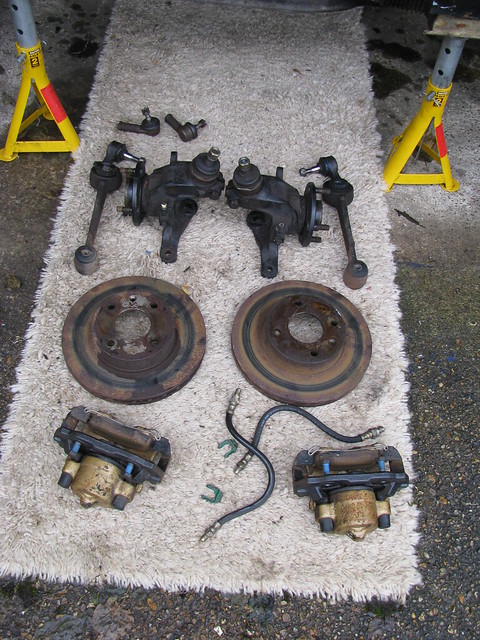
Looking back at my dismantling photos I can see the original builder used traditional rubber brake hoses which were simply screwed into the caliper without a copper crush washer.

Front brakes, hubs, etc by Sabrebuilder, on Flickr

EDIT: This is the wrong photo, please see post #408 below

A bit of a retrograde step but i'm thinking of reverting back to rubber hoses.:ohwell:
21 Oct 2019, 9:09am Mechanical Overhaul
Hi Peter,
thanks again for your suggestions but I think I have confused matters by posting the wrong picture above. It should have been a picture of my rear brakes which is where I'm having the issues.

Here is the correct picture......

Parts removed today by Sabrebuilder, on Flickr

Sorry for wasting your time.
26 Oct 2019, 7:14pm Mechanical Overhaul
Thanks for the photo's.
I have bought some Borg and Beck traditional hoses. Here are some comparison photo's.

Goodridge v. Borg and Beck hoses by Sabrebuilder, on Flickr

Goodridge v. Borg and Beck hoses by Sabrebuilder, on Flickr

And they are clearly not designed to use copper washers.....

Borg and Beck brake hose by Sabrebuilder, on Flickr

When you tighten them up you can feel them deform and create a good seal. No leaks so far!

With hindsight I'm thinking that it was actually the copper washer that was preventing the original Goodridge hoses sealing properly.
On my front calipers I did not fit copper washers and no leaks.

November 2019

1 Nov 2019, 8:18pm Engine Mechanical Overhaul Chassis and Body Electrics Interior & Trim
Engine running....

Today was a momentous day in my somewhat protracted build.

Last week I spent a day troubleshooting a strange electrical fault. I thought there was a fault with my ignition switch but I eventually worked out that a light green wire for the heater was swapped with a normal green wire for the dashboard instruments. I have no idea how they got mixed up but easy to fix.

Yesterday, I fitted my new Bosch HP fuel pump so today I primed the pumps, and then re-installed and connected up the ignition coil packs.

That only left one thing to do and that was to turn the key and see if it would start.

It started first time but immediately died and then wouldn't start again. I quick check over and I found I had left the fuel pump fuse out after priming the pumps :doh:

After re-inserting the missing fuse I then restarted and it ran fine albeit a bit clattery while the oil filled the tappets, etc.
After a spot of lunch and a quick check over, I then ran the engine at 2000rpm for 20 minutes to 'set' the catalytic converter. (Recommended by the supplier)

Everything seemed fine with the electric fan cutting in and out at the set temperature. :peace::peace::peace:

Here is the obligatory video ....

BMW Engine running again by Sabrebuilder, on Flickr


I last ran the engine in the BMW donor car in October 2014 and can't believe it's taken 5 years to get to this stage! I installed the painted body tub this time last year on the 3rd November 2018.

I am very pleased that the engine is running smoothly with no rattles or noises.

Further checking showed the Tacho, Oil pressure, Coolant temperature, Fuel gauge and Clock all working fine. The car is still raised on jacks so I was able to test the clutch, prop, rear drive which all work fine but the Speedo has so far refused to budge?:noidea:

I also checked the engine with my fault code reader and there were no fault codes bar the EVAP purge valve which is not fitted.

Once I get the Speedo working I can think about refitting the wheels and driving out of the garage for the first time.:madgrin::madgrin::madgrin:

Happy days.............

Peter
2 Nov 2019, 5:48pm Mechanical Overhaul Interior & Trim
Speedo fixed

Amir and Jack - thanks for the feedback.


----------------------------------------------------

I have fixed my speedo today. After removing the dashboard (again!) and checking all the connections I moved on the looking at the sensor mounting.

It's almost impossible to reach from below the car and I needed to adjust the gap between the speedo sensor and gearbox lobes. I couldn't face the job of removing the whole gearbox tunnel so I cut a hole in the side which will be plated later. The manufacturing instructions say that the gap should be set at 1-2mm and I had set it up at 2mm when I installed the sensor. Reducing this to approx 1mm fixed the problem.

Speed Sensor adjustment by Sabrebuilder, on Flickr

With 4th Gear selected the speedo is registering just over 10 mph at idle. I seem to have clocked up 1.8 miles already during testing. Final calibration will be done once I have selected my tyre size which is still TBD.

Speedo working by Sabrebuilder, on Flickr

Happy days.........

Peter
10 Nov 2019, 6:11pm Engine Electrics
Noisy Fuel Pump - fixed!

Thanks Jack and Robin.

-----------------------------------------------------------------------------

During my engine starting trials I noticed that my very expensive brand new Bosch '044' high performance fuel pump was very noisy. It sounded like it was straining to pump enough fuel through the system. Looking at the pump's spec I feared I had over spec'd the pump as it is rated at 285 litres/hour whereas the Ford lift pump is rated at only 120 litres/hour. Clearly a poor mismatch and a silly mistake.
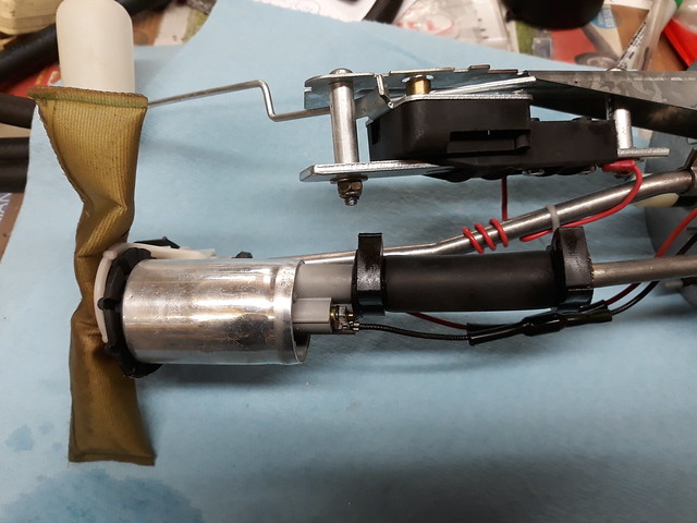
Here is a picture of the Ford in-tank lift pump.

BMW Fuel Pump trial by Sabrebuilder, on Flickr

Now I remembered that Mike Garner who built a Marlin Cabrio a few years back had suffered with a noisy HP pump so I asked Mike to comment. As the Granada fuel tank has a built in sump Mike suggested ditching the external Bosch pump altogether and using a BMW HP pump in the tank.

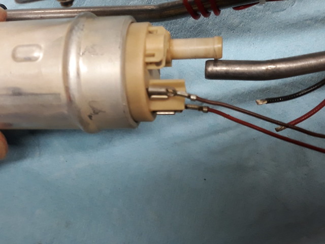
I really liked the simplicity of this idea so bought a used BMW pump to see if it would fit in the Granada tank unit. (I had to buy another BMW pump as my original donor car's one was sold long ago)

BMW Fuel Pump trial by Sabrebuilder, on Flickr

Comparing the two pumps It certainly looked feasible so it didn't take me long to remove both pumps. The BMW HP pump is about 4cm diameter and 12 cm long and a bit bigger than the Ford lift pump.

BMW Fuel Pump trial by Sabrebuilder, on Flickr

The BMW pump neatly fits in the Ford pump support cradle but is just a few mm to long.

BMW Fuel Pump trial by Sabrebuilder, on Flickr

So I used my mini tube cutter to remove a short piece of the steel feed pipe. I used a new piece of suitable rubber hose as the old Ford hose had been softened and swelled by the fuel.

BMW Fuel Pump trial by Sabrebuilder, on Flickr

Here's the BMW HP pump fitted and connected with a short piece of 'in-tank' compatible fuel hose.

BMW fuel pump in Ford unit by Sabrebuilder, on Flickr

The result is everything seems to run fine. I've only run the engine for about 10 minutes but no issues.
I need to run a thicker cable from the fuel pump relay to the pump in the boot as the Sabre loom is only 1.0mm (BMW loom is spec'd at 2.5mm) and I’m going to remove the LP pre-filter as it is no longer required. I’ll also have to put an extra couple of p-clips on the hoses where I’ve bypassed the filter and the external HP pump.
Thanks again to Mike for such an elegant solution and probably more reliable as the pump exactly matches the BMW design and engine requirements.

I just wish I’d thought of it at the outset! 😊

It's been a 're-work' week rather than progress but I'm really happy with this solution.

...peter
P.S. anybody want to buy a very slightly used Bosch 044 HP pump??:heh::heh:
15 Nov 2019, 7:19pm Chassis and Body
Bling bling..........

After years of being stored outside, the Sabre's front quarter bumpers and light plinths had gone rusty so I have had them stripped and re-chromed.

Bling by Sabrebuilder, on Flickr


Needless to say but, I am delighted with the results.:biggrin::biggrin::biggrin:

Bling by Sabrebuilder, on Flickr

Re-chromed by Vehicle and General Polishers and Platers Ltd, Arlesey, Bedfordshire.

:smokin::smokin::smokin:
24 Nov 2019, 8:02pm Engine Mechanical Overhaul Chassis and Body
Thanks again to Jack and Paul for your kind comments.

----------------------------------------------------------

This week I have been making permanent the bypasses to the external HP fuel pump and pre-filter which meant adding hoses and a few 'p'clips. I've kept the original mounting holes should I ever decided to revert to my original design.

I've also been cleaning and painting my 'spare' used power steering rack which I hope will not leak like my so called 'reconditioned' one. The rubber mounting bushes are shot so I have had to order some rather expensive Superflex poly bushes since the original Ford bushes are like the proverbial hens teeth.
My 'rack is made up of a Mk3 Granada power rack fitted with Sierra manual rack tie rods which are shorter than the Grandad ones. This is to get the track width correct for my Sabre which has Sierra donor suspension components. So I have also been swapping tie rods from one rack to the other.

Whilst testing my engine a couple of weeks ago, I had noticed that the fuel tank was pressurized and the breather vent seemed to be permanently closed. The Ford vent closes off if the car is upside down to prevent fuel spillage. I have now discovered that the valve closes when tipped over by more than about 15 degrees. I had originally installed it attached to the filler neck, as designed by Ford, but on the Sabre the filler neck is rotated by about 120 degrees. This meant the vent was mounted at an angle which meant it was permanently closed.
I have now re-mounted it so that it is vertical.

Fuel vent valve by Sabrebuilder, on Flickr

Fuel tank breather vent valve re-positioned to be vertical.

Fuel vent valve by Sabrebuilder, on Flickr

It may not look it in the photo but it was set with a spirit level to confirm it is now vertical and venting the tank correctly.

Next week I hope to get the 'rack back on......

.........peter

December 2019

1 Dec 2019, 9:14pm Engine Electrics
Misc updates

So this week I finished refurbishing my other S/H steering rack and I have re-fitted it and reconnected the hydraulics. So far so good and no leaks but time will tell if it's OK.

I've also fixed the intermittent wipe so now I have 'Not so fast' , 'Slow' and 'Intermittent wipe' that is adjustable between 3 and 20 seconds. The old Lucas wipers were not the fastest in this world! Rain must have been lighter back in the day.:lol:

I then installed my horns and eventually traced a silly wiring fault which was two of the relay terminals swapped over.:doh:
I mounted the horns on a couple of the radiator mounting bolts.

So just one picture this week.....

Horns by Sabrebuilder, on Flickr

....peter
12 Dec 2019, 7:48pm Engine Mechanical Overhaul Chassis and Body Electrics
Body Building....

No, I haven't been to the gym but I have started to assemble the Sabre's body panels.

But first, I had some housekeeping jobs to do. One was to make the engine air intake hose fixing permanent.
It was temporarily held in position with a couple of tie wraps so I bought a suitably sized flange which was bolted to the radiator support frame.

Air Intake flange by Sabrebuilder, on Flickr

I also had to fix the radiator frame with nylocs as it had previously been fixed with plan nuts.

I could then move on to fixing the inner wings and the radiator cowl.

Inner wings by Sabrebuilder, on Flickr

Even though they have been fitted before by the original builder they still needed a fair bit of fettling to clear the wiring loom and the radiator frame brackets that I have added to move the frame forward to accommodate the BMW engine. They are only loosely fitted in this photo as they need to be removed to paint the inside faces and they will only be aligned and tightened once the bonnet is in place.

Inner Wings by Sabrebuilder, on Flickr

I also had to re-position the air intake filter as it was fouling on the inner wing but I managed to move it back a couple of cm's.

(sorry about the quality of these pics as they were taken on my 'phone)

A bit more fettling required and I need to cut a hole to be able to get to the brake servo bleed screws. So until next time.........

.....peter