MadaboutKitcars

This is a read-only archive of the old Madabout Kitcars forum. New posts and replies are no longer possible, but every thread is still here to browse and read.

Spare Wire!

13 Aug 2008, 11:18am
I have completed the installation of the wiring but ended up with a spare end!

On the Marlin loom the Wiper and Washer wires are all connected up but I have Grey/Blue and attendant Black (as a pair taped together) coming out of the loom in approx. the same place that are not mentions on the sketch and with no apparent place to go.:frusty:


Second issue how do I modify the Hazard circuit to make it operate with the ignition off. It looked at first glance like a Green/Pink connection but I do not seem to have solved the problem yet.
I am using the Rover set up and everything works as it should just no hazards without ingition. :icon_confused:
13 Aug 2008, 3:21pm
Just ditch the grey/blue seal the ends off!

For the hazards you need to feed them with the purple perm live!

Some used a relay (secondary) some used diodes!

I being useless at wiring opted for the diodes as they were (for me) much easier to work out
13 Aug 2008, 5:25pm
Can help you on the hazard switch. I use the stand Rove 3 pin flasher relay. And the standard mk3 Rover switch. You will find the hazard circuitry one of the most complicated bits of electrical works in the car!

Also make sure you have a indicator lamp fitted. Other wise it will be a high pitch screech from relay, not a flashing.


I'm working on your grey/blue wire. It's been a while!

Any chance you could trace it to the other end? where does it end up?

Only grey/blue in the Rover manual, is cooling fan.

If I remember rightly, can't remember device, but there was a different colour. Maybe due to Marlin not being able to get the right colour wire. Wire every thing up and see what's left. :)
13 Aug 2008, 5:56pm
If memory serves the grey blue was for the fan if you run it from the rad as I did, as you had the choice or that or runing it from the engine temp sendor switch.

In the matter of the hazzards, I ended up with two relays which Simon who was as Marlin suggested.

Steve
14 Aug 2008, 11:03am
We are making progress;
Steve is correct the Grey Blue wire when shorted to the black operates the marlin relay and starts the fan, well done that man.

I guess I have the option to use this wire to start the fan manually i.e. during a 'hot run' or during track running or fit a temperature switch on the rad. manual switch I think I like the control.

Thank for that I now know what I need to do.


The Hazards are not to easy thus far...

I have tried wiring to John' s sketch but it powers up the ign I guess by a back feed up the Green/pink.

Just so we are all together here, the winkers and the hazards all work as they should with the ign on.

With the ign off and the green connected to the Green/pink the car powers up up like the ign is on.

So 'a diode' Craig says so I connect a diode in line with the Green and the green pink and the pod hazard lamp lights up when the switch is operated but the lights don't work/flash. I have tried a 5amp power diode and still it will not operate the lights.

So Craig, mate where did Marlin tell you to stick the diode!

JohnC
14 Aug 2008, 3:31pm
John, I tried to copy from John Dry!! But wiring is not a strong point and after I while I just played about until it worked. I may have the diagram still somewhere but I did find myself in the same situation as yourself in that everything worked with ign on but not with ign off.

What switch are you using?

On the savage switch pin 1 is green (switched)
pin 2 purple (perm feed)
pin 3 not used
pin4 earth
pin 5 illumination
pin 6 not used
pin 7 indicator red/white wire
pin 8 indicator green/white wire

You need two diodes to stop feedback to each side of the car


I just ditched the manual fan wire and went with ecu control
Craig
Ps I have emailed you the wiring diagram
14 Aug 2008, 5:43pm
I'm a bit stumped as well with hazards??

Mine would not work until I wired up the green/pink as per diagram with the ignition off.

As for fan. You should have another grey/blue at the rear as well. To control fan. You can connect this to the ecu to control fan as I did.
20 Aug 2008, 5:39pm
Okay so we are clear what I am referring too I have a standard Rover 200 or 25 hazard switch and the standard supplied Marlin loom (the switches from all shades of 200/25 are the same I have one of each).

The detail of this thread identifies my problem so I will not repeat it again.

For the indicator circuit to work......

The hazard/indicator circuit works with the hazard switch feeding power from pin 3 to the hazard relay (the relay that clicks during indicator/hazard lights operation). Power is normally fed from pin 1 of the hazard switch, (green - switched power feed).

The hazard relay, if loaded by the stork being operated or the hazard switch operating, will oscillate the current to the bulbs so with the ign on and the indicator stork operated the load is provided and the relay oscillates and the selected bulbs flash.

With the ign off the indicators do not work.


The indicator circuits is always fed via pin 3 from the switched 12 volt pin 1.

The hazards circuit is always powered from pin 3 via the permanent 12 volts on pin 2.

As the hazard switch is operated the power from pin 2 is directed to pin 3 and on to the hazard relay, the other multiple contacts in the hazard switch are used to switch the relay output and load it with all the indicator bulbs, hence all hazards lights are flashing.

That's how it should work.:biggrin1:


In my circuit if I fed the hazard circuit with power with the ignition off, the car ignition was 'back fed' from the same supply which is not wanted or required.

What I found was that the hazard relay was hard wired direct to the switch live common point, and not from the hazard switch pin 3. As a result if I applied power to the relay with the ignition off that feed lit the ignition up. If the ign was on the indicator worked independent of the hazard switch.

I cut the green at the hazard relay and loomed in the correctly fed for it from the hazard switch pin 3 and all works fine.

Interestingly there was no Green/Pink (pin 3) wire in the Marlin loom to feed the hazard relay and the green feed to the relay was already installed so I can only assume that the loom was designed for a different hazard switch circuit that somehow prevented the back feed to the ign circuit.

If you use the Rover hazard switch you may need to make the same modification to the supplied Marlin loom.

I can only stress that this was the fault I had and may have been a faulty loom, on the other hand it may have been designed for a different circuit installation, we may never know.

On a side note the RAVE diagram is so complicated its unreal, I dismantled a switch and re-drew the circuit before I could identify that was causing my fault.

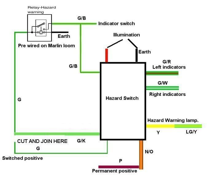
Interestingly that makes 'limpabit's' circuit above correct provided the green wire does run to the hazard relay as shown.

All my electrical work, baring the clam mounted lighting is now complete.

I must get an exhaust !!
20 Aug 2008, 8:21pm
Hi John.

The diagram is not too clear. Sorry about that.

With mine, and the diagram above, what I had to do, was cut the green "switched" wire in the Marlin loom going to the Hazard Relay.

Wire the Green/Pink of the hazard switch to the green wire going to the relay.

Then wire the green wire from the hazard switch to the other end of the green wire just snipped "switched power".

Is this your solution John?

I told you this hazard switch was complicated!
20 Aug 2008, 9:06pm
Yes that's what I had to do.

Sorry I credited the wrong person for the diagram it was yours not John's.

It would seem then that the Marlin loom is at fault if you use a Rover hazard switch!
20 Aug 2008, 10:44pm
It's a prerequisite to building a 5exi that you be called John. It helps confuse things :).

Just for the record, my wiring is totally different for the hazard, as I used a Savage switch, which is simply a double latching switch..... the simplicity of which only serves to complicate matters.

Anyhow, good to hear another glitch has been overcome. How have you done your wipers John C? Did you put an intermittent relay in? Sticking on the wiring theme, have you checked the voltage drop across the Marlin loom, with the headlights on? My feeling was that the loom could benefit from bigger wires for the lights - there's nothing that irritates me more, than headlights that are like candles in jam jars!

I have a 170 amp 12V feed running from my alternator to a distribution box under the dashboard - with 14v registering at the battery, headlights on, fuel pumps running, I still get a noticeable drop in voltage, so what this would be like with the Marlin loom I wouldn't like to know.
21 Aug 2008, 11:28am
I have not wired up the clam based lamps yet as I have no body parts yet.
Anybody got any bits they want to sell?

Wipers the motor works in two speed and self parks I had not thought of intermittent!

I have not checked the loaded voltage but you are right the battery feed does need upgrading.


On a final note for the electrics I would like to mention the Rear Fog Switch.

I have not seen any other threads on this topic but its a pig of a problem if you are not aware of the issues.

The Rover rear fog warning switch is a momentary operation switch that tells the MFU under the drivers knee to turn the lamp on if there are headlights turned on.

You press the switch again to tell the MFU to toggle them off, now this is not a lot of use for a switch to do if you did not incorporate the MFU into the 5EXi and why should you!
So a different switch is required to switch on when required and switch off when not needed.

You can use the front fog/spot lamp switch but the logo on the switch is wrong and the contacts operate differently and all the switch sockets are keyed to stop the original Rover car builders getting the circuits mixed up.

You have to choose your switch then wire in the socket that fits it.

After falling into this one as well I installed the green socket of the rear fog switch.

I dissembled 5 switches to get all the right bits and contact configuration to re-build a toggle on/off with the correct logo on the front, in the end that was a rear fog switch front and an a/c switch contacts and socket, all the other bits were broke or of no use by the time I was finished, but its now right and as it should be.

The keyed socket was then changed to a white one to fit the body of the switch.