MadaboutKitcars

This is a read-only archive of the old Madabout Kitcars forum. New posts and replies are no longer possible, but every thread is still here to browse and read.

Swifty's Navigator

21 Sep 2014, 7:46pm
I suppose you could send the pic to one of those suppliers and ask?
22 Sep 2014, 6:07pm
davecymru Thanks for the link, that's the type of latch i was thinking about, cheers.

Started to think about the interior and have come up with an idea that i hope will both look good and work in regards to the installation.

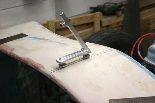
Made a few bits to see how it will look for now.


IMG_4707.jpg
IMG_4708.jpg


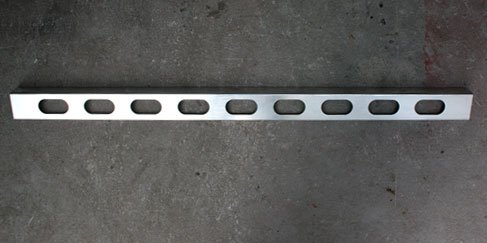
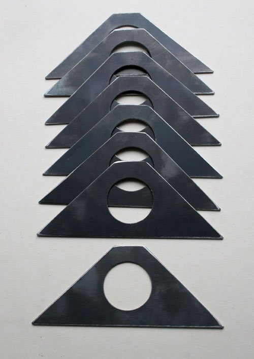
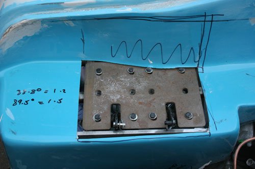
Not going to say exactly where these will be used for now but i am sure some of you will possibly know where they will end up. The first image is 1.5 mm ally plate with slots, second image is 1.5mm mild steel plate.
22 Sep 2014, 6:37pm
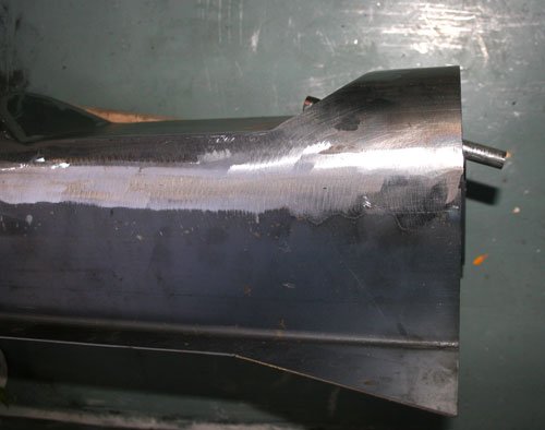
Finally finished the off side rear wing, i had to cut back my first attempt as it was not quite right when the filler was applied.


Attachment “IMG_4713.jpg” from the original forum could not be reliably recovered.
IMG_4714.jpg


The wing is now symmetrical with the nearside and the gap between the cockpit edge and wing curve is even both sides which is what i was looking for.

My first attempt was too high so i cut back the fiberglass to the foam filler then removed some of the foam to give the correct height, fiberglass the whole area again followed by a light skim of filler, then used the cardboard templates i made from the nearside arch profile.

IMG_4709.jpg


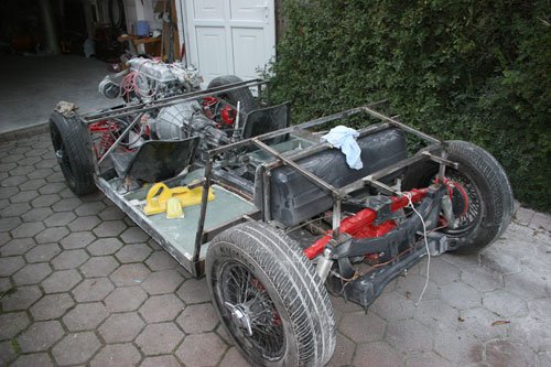
Capped the sub frame box section open ends with 1mm plate welded into position to prevent future corrosion.

Also removed the section which tied the front frame to the rear frame as this is the area i am going to add the bits in the previous thread too, moved the tank forward slightly to give me as much room in the boot space as is possible.

The floor i will finish off internally with 2/3mm ally plate possible leveling the front well with the sub frame top and angling the rear well from the front down to the back, the angle i was thinking of using to aid the seat angle backwards to give a more sporty feel and keep the rear of the seat as low down as possible, but again i won't know if this works until its finished.

Attachment “IMG_4715.jpg” from the original forum could not be reliably recovered.


The wire in the mig welder ran out half way through welding the sub frame so i decided to trial fit the bonnet to see how it looks.

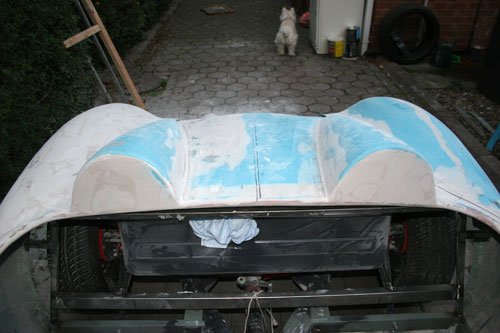
The center bulge in the bonnet circled in red is now off center (slightly to the right) to the car's center line and out of line with the bulge in the dash top which i re-done in a previous thread so i now have to come up with an idea to align the bulge, straighten the grill area out and also cover both front wheels with the bonnet oh and also make the gap between the headlights and the grill equal, circled in red.

So to try and achieve all of these realignment issues will be a challenge especially the bonnet bulge.


Well that's it for now see you all soon.
23 Sep 2014, 6:28pm
Swifty - Good luck with sorting out the bonnet.

Obviously I will be following how you do it with great interest.

Have you worked out how to hinge the bonnet yet?

Everything else seems to be coming together nicely. :cool:

Cheers, Paul. :)
23 Sep 2014, 7:53pm
Paul I have idea's but until the bonnet is finished i am unsure if it will work, i may change the way the grill area angles down to the ground but again i need to see how it looks once the alignment issues are sorted.

One thing i am looking at is to strengthen the bonnet structure which will tie in with the hinge mechanism, so until i sort some of the other issues i can't decide on the way to go.
27 Sep 2014, 7:34pm
Today i tack welded with the mig both side frames and worked out how to make them removable to be able to fit an ally plate side panels after the body is bonded to the chassis, i am after a seamless panel finish if possible and trying to hide the fiberglass side panels to give the illusion of a race chassis and interior but i may be given myself a lot of problems but so far it looks good.

My next move is to tig weld the side frame's as i have used round tube and tig gives a smooth even weld which will add to the illusion.

One question i have for you guy's is what is an acceptable rear arch clearance so that the tyre's don't catch the top of the arch when cornering etc, i can see Mr T had the tyre's very close to the arch rim?
27 Sep 2014, 9:32pm
Assuming you have MGB 4.5x14 wires fitted (as I do), rear wheelarch clearance depends on four factors: tyre size; number of leaves left in rear spring; rear lowering block choice; and the weight of the occupants.

With 175/70/14 tyres, the top three loose leaves removed from the rear spring stack and a 75mm lowering block I had no clearance issues whatsoever. Ground clearance and ride quality were a different matter, however - I had to crawl over speed bumps and at 50mph on 'B' roads the car was so jumpy and skittish it was too scary to drive any faster.

To address these issues I fitted: softer, 150lb front springs (cut down by a coil and a half); 175/80/14 tyres; a 50mm lowering block over the diff; and removed another leaf from the remaining spring stack.

This made a world of difference to the ride and handling and I had no clearance issues with just me aboard, or while driving my (then) 12y/o son about. Then I took an adult passenger out for a drive on the bumpy B roads round here and found that the nearside rear tyre fouled the arch over every bump. Thankfully it didn't do any damage, but it sounded and smelled awful.

Taking the lowering block out raised the rear by a couple of inches and sorted the fouling issue out, and, with a few other tweaks, my car can now be driven with real vigour on any road surface and at ridiculous speed with complete confidence.

So, the suspension setup I now have is as follows:

Standard dampers (new);

150lb Spitfire front springs cut down by 1.5 coils (170lb would also be fine);

7/8" Spitfire anti roll bar;

Spitfire steering rack (quicker than Herald/Vitesse but not too heavy with a 14" tiller);

Blue poly bushes all round;

Three loose leaves removed from the rear spring stack, plus a further leaf taken out of the remaining stack;

No lowering block, diff clamped directly to spring;

4.5x14 wires wearing 175/80/14 tyres (20psi front, 22 psi rear);

Toe in on rear wheels, toe out on front wheels.

On that last point, I haven't actually measured the angles, I just trial and errored it until it stayed straight as an arrow at high speed but turned in with a lovely balanced feel when you began to give it some steering input.

Others may prefer a stiffer setup for the track, of course, but for the road I reckon I've got mine just where I like it now.

Good luck getting yours set up how you want it. :)
28 Sep 2014, 12:54pm
On my old Spyder i fitted a swing spring and a 1" lowering block on the rear, with 15" wire wheels, sporting 165 SR 15's.

TBH it was a bit _too_ low and i did get tyre scrub occasionally!
28 Sep 2014, 6:46pm
Mr T A very thorough answer, thanks for the info. I have the later rear spring fitted with a 3/4'' block so no leafs removed at the minute, i also have 14'' mgb wheels fitted so are trying to work out how much clearance is required between the tyre and wheel arch at the top, i would like as little as possible for the looks aspect but don't want the tyre fowling.

davecymru Thanks for the info, i think it is a case of suck it and see.

Made a little progress with the sub frame adding bits to various points.

IMG_4719.jpg
IMG_4718.jpg


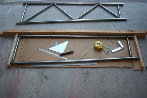
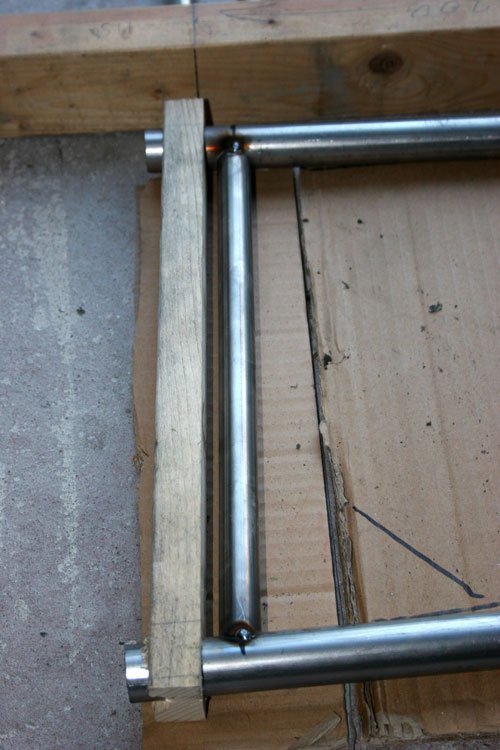
Started by making two tubular frames that will go between the front and rear half sub frame. Tacked with the mig for now and will go around the joints with the tig for a smoother weld. Used a simple wood jig to space the top and bottom tube runners to follow the angle of the body sides and give the correct spacing.

Not a hole saw in sight just cut to length and finished with a half round file to match up with the tube, brought back memories of my apprenticeship many moons ago when all work like this had to be done by hand to prove you were capable of using hand tools accurately, oh happy days.

IMG_4722.jpg


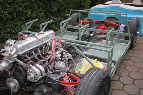
Also added box section to the front sub frame which will be the mounting points for the dashboard and anything else fitted behind the dash. Welded into place four plates with holes to allow the side tubular frame to slide into place after the body and side ally plates are fitted, the plan is to then weld the tube frame to the four brackets.

I am now looking at how to mount the pedals and it looks like i'll have to cut and fabric the box section on the drivers side to accommodate the pedal mount plate and add some strength.

Well that's it for now see you all soon.
29 Sep 2014, 7:27am
Swifty - More nice work as always.

You are definitely on your way to having one of the nicest cars built to date. :cool:

Good luck, Paul. :)
5 Oct 2014, 8:07pm
A little progress made to the sub frame and boot frame.

Started making a screen center support pillar out of ally that will also be the mount for the rear view mirror, once it's finished i will post some pictures.

IMG_4725.jpg


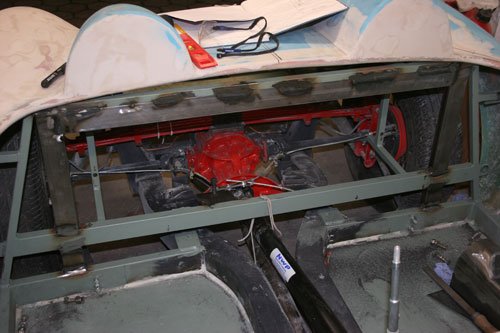
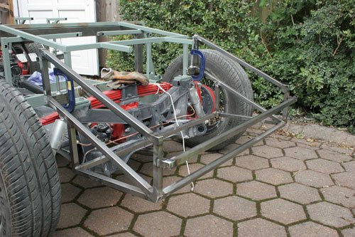
Started work on the boot frame which i had to do with the body in place to work out where the box section would fit. Due to the body being in place the welds are not the best as the room to work in was limited but will finish the welds once the body is removed.
One thing that the frame has pointed out due to the fact i made it square and equal dimensions is just how far the body is out from one side to the other.

IMG_4729.jpg


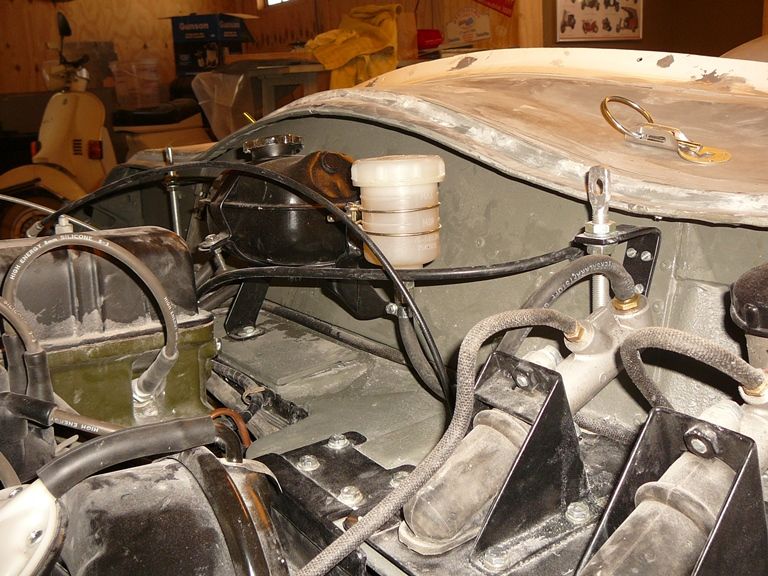
Fabricated a frame out of 20 x 20 box section to mount the pedals and brake/clutch cylinders. It looks like the original brake/clutch master cylinders are too high and will obstruct the bonnet so i will have to look around for a solution.

Has anybody found a solution to this problem, maybe a remote reservoir!

IMG_4730.jpg


Added 50 x 20 box section around the rear sub frame which i may use to mount the seat belts eye bolts.
Also fitted a plate to mount the hand brake pivot bolt.

Well that's it for now, see you all soon.
5 Oct 2014, 9:13pm
Will the frame and bodywork be able to be removed from chassis?
5 Oct 2014, 9:36pm
At the minute the body has not been bonded to the chassis but will be once i am happy that all the work has been completed and the boot frame is part of the rear sub frame which is bolted to the chassis.
6 Oct 2014, 5:11am
swifty wrote:
Has anybody found a solution to this problem, maybe a remote reservoir!


Michiel fitted a remote reservoir on Spyder #47.


Using a Spitfire bulkhead in my Frankenstein build was how I resolved this particular issue.
( As neither the metal framework, nor the fibreglass bulkhead, worked for me. :icon_sad: )

Of those two solutions, I wouldn't actually recommend the work required for mine to anyone. :icon_wink:

Good luck, Paul. :)
6 Oct 2014, 4:26pm
Swifty, now you know why I went for floor mounted pedals..:-(
7 Oct 2014, 8:46pm
Paul Thanks for the picture, i knew i had seen these on the forum some where, it looks like i will use the land rover master with remote reservoir's if i keep the original pedal box.

Viatron I may give this solution some thought but will have to way all things up first. Thanks.

Finished the screen center support bracket today.

IMG_4740.jpg
IMG_4744.jpg


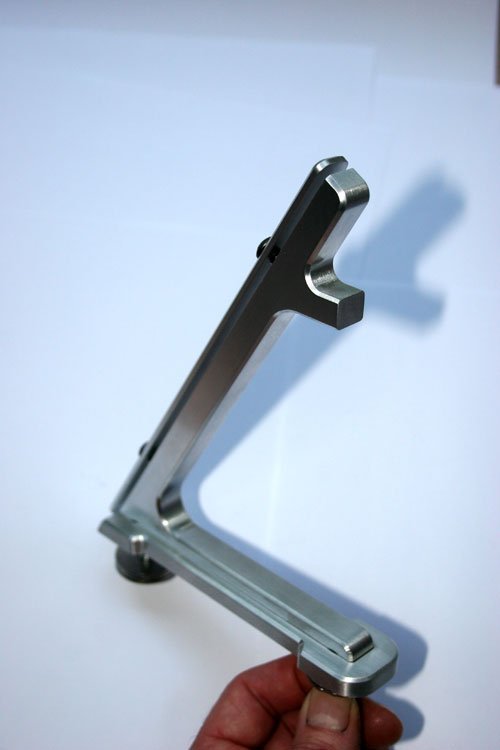
Machine out of ally with two 6mm studs to mount through the dash area. I did consider making it out of a solid billet but decided this was just as easy to make from three separate pieces, one for the body, one for the front clamp plate and the other for the base.


I decided on a 60 degrees angle which i think is about right, all the edges have a 1.5mm chamfer following the profile. The small lug near the top is where the rear view mirror will attach to, I've not drill this as i will have to buy the mirror first to work out the mirror mount foot print which i will copy out of ally and then machine a pocket to match the small lug profile to mount securely to the bracket, if that makes sense.

Also trial fitted the bonnet again to get to grips with the major surgery required for it to fit correctly, also i am looking to add side vent trims to the bonnet so i wanted to see how the various ideas i have will look, i find that if i look at a problem one day then come back to it another day i can see it in a different light sort of speak.

Well that's it for now see you all soon.
8 Oct 2014, 8:10am
What bit was easy, balancing it on top of the bulkhead...
9 Oct 2014, 12:17pm
Swifty - At this rate, your car will look better than some original factory cars! :cool:
10 Oct 2014, 11:05pm
Paul L wrote:
Swifty - At this rate, your car will look better than some original factory cars! :cool:


I agree! stunning work
12 Oct 2014, 6:55pm
Paul L & DapperDan Thanks for the comments.

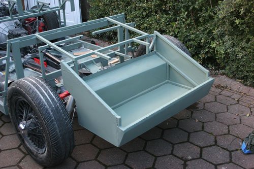
Finished the boot compartment off today, i basically made the frame with the body loosely fitted so that i could see the maximum area i had to work with then dropped the frame down onto the floor to remove the body and fully welded the frame before fabricating the sides etc out of 1.5mm mild steel sheet, i am possibly thinking of lining the inside with ally sheet but will wait and see what the steel looks like once painted the same colour as the chassis. One thing i will do is extend the sides up to suit the curved profile of the body to both bond/stiffen and seal.

IMG_4763.jpg


Frame in position after removing the body to check all is ok after fully welding the joints as you can get some movement after welding, all was ok so next moved onto cutting and bending the 1.5mm mild steel sheet to suit the frame, all open ends of the box section were capped to prevent future corrosion.


IMG_4764.jpg


Sides etc welded in place and etched primed ready for the top coat.

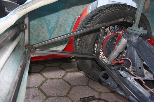
I've made the frame sit unaided on the rear sub frame to make it easier while welding into position with the body in place. This had to be done due to the size of the boot frame (the distance it sticks out to the rear) and the front bulk head sub frame means i can't drop the body onto the chassis so i had to be able to sit the frame on the ground, drop the body in place then reach through the boot hole in the body and lift the boot frame into position to weld without using clamps etc to hold in place.

IMG_4767.jpg
IMG_4768.jpg


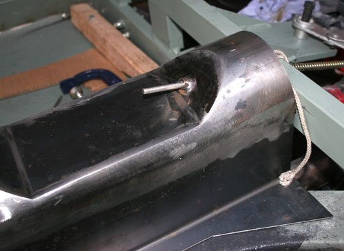
Also welded a piece of 10mm o/d stainless pipe in position to guide the handbrake cable through. The rear of the pipe sits inside the 50x20mm rectangular section to help support the tube, I've not welded this section of the pipe to the 50x20 section as i want to be able to remove the prop shaft tunnel as and when required in the future.

Well that's it for now see you all soon.
12 Oct 2014, 7:51pm
Inspiring to see all these variations for framing and boots.
19 Oct 2014, 7:08pm
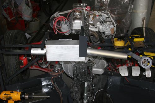
Made a little progress over the weekend. Ive decided to fit a heater which i bought online from car builders solutions, it's a 4kw unit in a small box.

IMG_4769.jpg


Made a distribution box from ally sheet as i wanted warm air blown into both foot wells, the main box is 1.5mm ally sheet folded with welded seams. The tubes were hand rolled from 1mm ally and tig welded up the seam, each tube is welded to the ally box section. The tube ends are blanked off with a hole in the side so that air is blown down over.

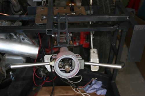
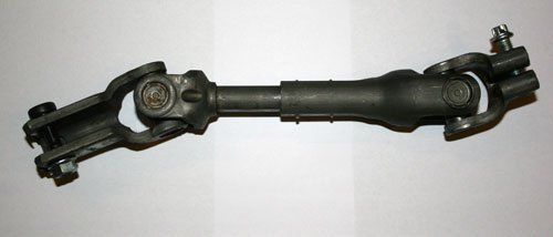
Next job was to start mounting the steering column. I paid a visit to a local scrap yard and came away with two UJ's attached to a 300mm rod from a corsa, this will be used to align the spitfire steering column to the lower steering box rod with a slight modification.
Will make a couple of adapters to mate the corsa UJ's to the spitfire parts.

IMG_4771.jpg
IMG_4779.jpg


Used the original spitfire steering column u clamp by fabricating a bracket to the front sub frame. You can see the steering column hanging off the bracket. The second picture is of the corsa steering column parts.
19 Oct 2014, 7:22pm
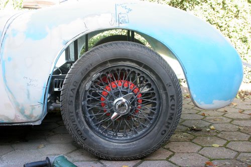
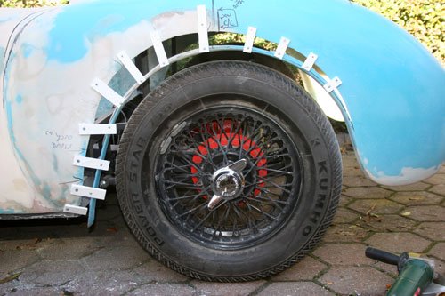
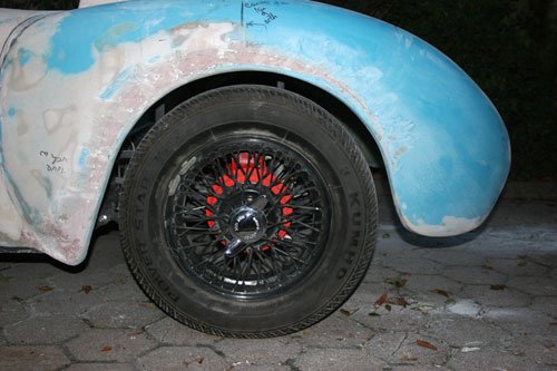
After working out what is required for the steering adapter i decide to start work on the rear wheel arches to fix the uneven gaps.

IMG_4773.jpg


Picture of the near side rear arch before i started to cut and shut.

IMG_4775.jpg


Cut around the arch then used a wood spacer between the Tyre and the cut edge to get an even curve.

IMG_4777.jpg
IMG_4776.jpg


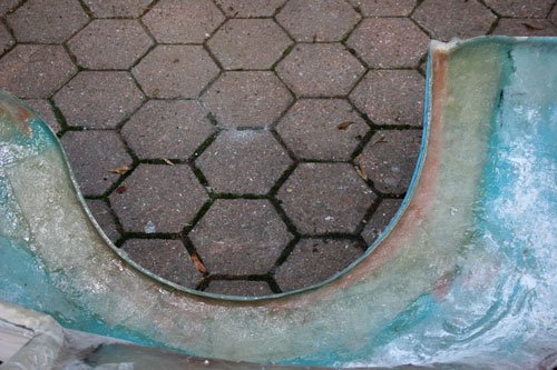
Gap glassed up with four layers of fiber glass and roughly filled in for now, the leading edge will have to be blended in as its too low at the minute, i intentional left it longer than required until the body was refitted to the chassis to be able to see where it should blend in.

Both side have been done so its down to smoothing off with filler. This is probably the last job where i had to be able to remove the body so hopefully very soon the body will be bonded to the sub frame.

Looking at ways to mount the fuse board under the passenger dash board area but still be able to gain access for future maintenance. I am thinking along the lines of hinging the unit but will have to see what room i have to play with.

Well that's it for now see you all soon.