MadaboutKitcars

This is a read-only archive of the old Madabout Kitcars forum. New posts and replies are no longer possible, but every thread is still here to browse and read.

Another Cordite Is Born ...

14 Jan 2013, 10:12pm
You need to check the "file last updated" date currently october 2012 for my car
14 Jan 2013, 10:29pm
Hey Paul, that pic would make a nice Christmas Card.....!
14 Jan 2013, 10:38pm
Hey Mocha, you've got it! Were all C R A Z Y over here, zooming around in cars we made ourselves,breaking as many laws as we can, just for the fun of it!! Sometimes, I even drive with my windows OPEN!
14 Jan 2013, 10:45pm
micha wrote:
you have so many kitcar constructors in uk....in terms of seatbelts..why nobody is phoning somebody of the specialists like westfield, tiger racing or sylva to get a professional answer in terms of seatbelt mountings....also the kit constructor ( sammio) should be able to give a technically correct answer. here it seams that the kit builder is left alone to find a solution himselves...very poor.


Since when has Westfield, tiger racing and sylva been specialists in seatbelt mountings? What technically correct information would you like Ribble (not Sammio any longer, try to keep up dear boy) to give? Its easy enough to state regulations but its upto the builder to make sure that his/her own car is safe.
14 Jan 2013, 11:00pm
For our purposes the seat belt mounts just need to be 'secure' to be legal.

To be honest, if you skid into the path of an artic it doesn't matter whether you're riding a unicycle or driving a Range Rover, you've had your chips.

As part of my previous life I had to clear up the wreckage of aircraft from both sides that'd been shot down in the Falkland Islands. If nothing else, ejection seats have 'king good seat belts and they were almost always intact. Sadly, the pilots hadn't always fared so well...

So, build and enjoy your own car. Put the best harnesses in that you can manage. But if a thirty tonne truck turns over on top of you on the bypass even the best racing harness ain't gonna save you. :)
14 Jan 2013, 11:27pm
Mister Towed wrote:


So, build and enjoy your own car. Put the best harnesses in that you can manage. But if a thirty tonne truck turns over on top of you on the bypass even the best racing harness ain't gonna save you. :)


- but do make sure they are suitably colour-coordinated for the benefit of the coroners photos..
15 Jan 2013, 2:30am
And being a Tiger owner I can assure you that they know no more than is already available on this forum and possibly the iva manual! I think you miss the point of kit cars, they are built by the owners to the owners specification, we have a proud tradition of she'd building in the uk and generally I think most builders take their own safety fairly seriously, hence my decision to have a full welded cage fitted to my soon to be road legal tiger, not a legal requirement but after years of racing I have seen what can happen so have adjusted by technical spec to take that into account. There will always be those that do stupid things, believe me I've seen a kit car with one of the seatbelt mounts riveted on! But it would never have passed scrutineering, an mot or an iva,
15 Jan 2013, 1:49pm
Some of us might also argue that part of the enjoyment of updating the older type of vehicle, which is not liable to IVA inspection, is to research the available options. If the prudent owner wishes to fit the very latest in safety equipment it is through personal choice and not solely as a legal requirement, the major challenge being to fit any updates in a sympathetic manner.

- or go buy an off the shelf IVA compliant Cobra kit where its all done for you.
15 Jan 2013, 7:31pm
Sorry chaps, it was my own fault really, I tried to be polite and subtle. :rolleyes:

Paul L wrote:
...
micha - Welcome to my build thread.
I'm not worried about the V5Cs of the cars in the photos, the context was their front indicators, nothing else.
...


Micha - To remove any doubt whatsoever...
This is my build thread where I am documenting my build as best I can.
I hope that there may be things on here that might help others with their builds.
I also encourage other Sammio / Ribble builders to guide me & exchange tips & ideas.
It can also be used by my friends and family to see what I am getting up to.

It is NOT somewhere for you to complain about anything what so ever!
If I give you the benefit of the doubt, perhaps you don't know what poor forum form that is.
So if you must continue to rant, please take it away from here and onto the main forum, thanks.

Everyone else - Carry on. :icon_wink:

davecymru wrote:
... Now back to our main feature ...


And here is something I prepared earlier...

Goldilocks & the 3 front indicator choices...
Well my Classic Mini front indicators arrived in the post and thankfully they do look "just right". :icon_wink:


For the record, the new Mini lens is 54mm diameter vs. 70mm for the rear lens & 25mm for side repeater.

However, there are still two things I need to do before the indicators are ready for use:
The first is to add a separate earth wire that will be connected to the metal rim around the bulb holder.
As these lights were designed to be mounted to metal body work that would provide the required earth.
( This tip came from watching the Mark Evans "A Car Is Born" programme, as he used similar lights. :cool: )

The second job will be to establish the best place, & best way, to mount them onto the bonnet itself.
Whilst certainly not an urgent job, it would make a good little job for me to start working with fibre glass.
As I'd rather see how it all works with something small before I need to tackle something more substantial.
I just need to check the minimum working temperature as it may remain cold outside for a while. :icon_sad:

Stretching the fairy story theme a little bit further…

One hump, or two?
Once upon a time I talked about building a second car with twin humps after I had finished my first car.
That idea quickly when out of the window when the cold reality of building this one dawned on me. :rolleyes:

However, one of the interesting developments in the far away land of 'Ribble Kits & Classics' is humps.
All the future bodies with come out of the mould without humps, which will then be available separately.
This raises the possibility of buying an "extra" hump & retro fitting this car into a twin hump set up. :cool:

I will give this some serious thought, as I am conscious I already have quite an extensive "To Do" list as it is!
Once I have established just how many humps my car will have, I will order some padded heads for them.
I intend to use the company that did Mister Towed's interior, as they did a great job on his head rest.

Cheers, Paul. :)
15 Jan 2013, 7:47pm
Paul. How's about this for a deal. Now I've got your missing bits organised, if I chuck in a spare hump to say sorry for the delay, you can play with it with abandon, document how you get on and we're all winners :biggrin:
15 Jan 2013, 9:29pm
Andy - Blimey! You have caught me completely off guard there. :shock:

That is a very kind offer, as I know a lot of the issues have been beyond your control.

Thanks, Paul. :)
15 Jan 2013, 9:43pm
Re GRP and temperatures, its very forgiving. Anything over freezing and it will go off, just add more catalyst. A lead lamp with a filament bulb our under the job, then covered with a tarp will bring the temp up locally to set it off if you do have a problem.
One thing though if it is cold, mind as you breath out you don't get condensation where you are about to put on the resin. That tiny bit of contamination will make it go milky and it won't stick as well. Just hold your breath!
16 Jan 2013, 9:32pm
Removable Frame & Body:
Charman.tech made a good point on his build thread the other day about "thinking time".
I've also spend a lot of time thinking about my build (as anyone reading this thread can probably tell :rolleyes:).
Even though there is little to show for it, it gives me comfort when working out how to put this car together.

I know the whole re-body inspection process relies on the frame and body work being removable.
However, based on previous comments, this is based on theoretical, rather than practical, evidence.
( i.e. As long as there are visible brackets that appear bolted to the chassis, that is good enough. )

But the more I think about this, the more I want to make sure that I do nothing to prevent physical removal.
I have been putting a lot of thought into the rear of the car & there are a few areas I need to consider carefully.
These are the petrol tank, filler cap, the rear frame bolts themselves & the fuel hard line...

Access Behind Rear Cockpit Wall:
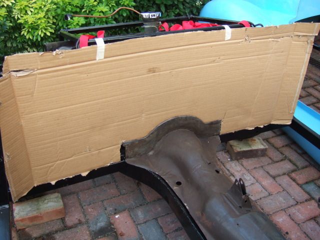
This was my 1st crude 'mock up' of the rear of the cockpit which will be "fitted" around my handbrake panel.


My understanding is that this panel is bonded / fibre glassed to both the floor & body shell for added strength.
So then it would be a case of cutting out a removable panel in this wall that would allow access behind it.

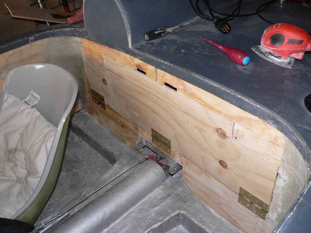
AndyP57 put a very discreet panel in his first demonstrator, for the fuel gauge wiring…


Mister Towed has a much bigger panel providing access to his luggage area…


Sorry, I feel another Goldilocks moment coming on...

"One panel is too big and the other one is too small...

:icon_twisted:

So I will have a look at the weekend to see how easy it would be to reach the following from inside the cockpit:
- Petrol tank mounting bolts - Might need captive nuts at the rear of the frame rail.
- Rear framework mounting bolts - Hopefully these can be removed without removing the petrol tank.

The filler cap securing clips, fuel gauge wiring & the fuel line connection should all be easy to reach.
The fuel line itself is the next area I need to make some changes to…

Fuel Line:
I bought a cheap and cheerful pipe bending tool to re-route my hard fuel line to the new petrol tank location.
My initial plan was to bend it around the frame and clip it all in place before bonding the body shell on.
The downside to this plan is there would be no way to disconnect the pipe in order to remove the body. :icon_sad:

So new master plan is to use some of this flexible fuel hose instead…


I would need to cut the existing fuel hard line at, or slightly above, the chassis level.
I would then run this flexible hose from the hard line to the tank, clipping to the frame work along the way.
But by disconnecting both ends of the flexible hose there would be nothing to stop the body coming off.

I would just need a simple rubber grommet to seal the pipe into the new floor (see below).

Rear Body Work:
Without doubt, my biggest headache is the area underneath the bodywork, behind the rear cockpit wall.
I have spent a lot of time trying to come up with a solution that will resolve these issues:
- Somewhere to mount my twin exhaust silencers.
- Inner rear wheel arches.
- Protection of, and access to, the rear lighting mounting points and wiring.

But no matter what I try, I keep coming back to DonnySoutherner's re-using bits of Spitfire solution…
( Which is why the new Ribble Navigator demonstrator being bonded to the Spitfire tub works so well. )


I plan to send the first photo to Spitfire Graveyard shortly so they know what I am looking for when I ring them.
( As I had enough trouble trying to describe the headlight rims I wanted over the phone. :rolleyes: )
If the price is right, then this is the road I will go down to sort out the back of the car.

Cheers, Paul. :)

Replies:
SeaNick - Thanks for the advice. :cool:
Although I might try wearing a mask rather than not breathing! :icon_wink:
19 Jan 2013, 10:24am
Well the snow has finally arrived in London with a vengeance…


But as SeaNick said the other day, at least the photo would make a nice Christmas card.

At least there are still a few little jobs I can be getting on with indoors...

Front Indicator Earth Wire:
This was a very simple & straightforward job (who said there were none of these? :icon_wink: ).
There were three tiny bolts & nuts to remove to allow the bulb holder to be separated from the seal.
( I will not be using these to mount the indicator to the bonnet, I will use fittings a bit further apart. )


Then I just recycled a length of the excess wire I'd already removed from my loom into two lengths.
I had to cut a very small hole in the rubber seal to thread the new purple earth wire though before I started.
( I will be producing my own version of the wiring diagram which will list all colour coded wired used. )


I then crimped small 'O Ring' connectors to one end & bolted it to the outer bulb ring as the earth connection.
I just had to cut a small "V" out of the rim to allow the wire a new route in which wouldn't foul when fitted.


So another little job done, and the philosophy on this build is still that every job done counts. :cool:

Rimmer Bros. Delivery:
Another very fast delivery of a big box of bits from them...


Next Steps:
We are hoping to head off for a family Panto later this afternoon...

Oh no you're not!

Oh yes we are!

Etc.
:rolleyes:

Although they did ask us to ring before hand to check it was did on.

But I have another couple of indoor jobs in mind if I get the chance.
( I'd dug out any bits & tools I might need from the bottom of the garden before the snow came. )

So until next time, take care, Paul. :)
19 Jan 2013, 11:33am
What's in the box?
19 Jan 2013, 11:38am
Radiator?
19 Jan 2013, 12:31pm
Sorry, just realised my shopping list was on the previous page...

Paul L wrote:

Rimmer Bros - January Sale
I had built up a list of assorted small bits & pieces I needed and this seemed like a good time to order them.
- All the retaining bits for end of throttle cable (previous clip went missing & was the wrong part anyway).
- Choke cable (as there is some fraying on the outer surround on my donor's one).
- Olive for petrol tank "fuel out" pipe (as I need to turn this through 180 degree, given the tanks new location).
- Clips for fuel & brake lines (easier to get these now rather than source them separately).
- A couple of small enamel Union Jacks which I plan to fit either side of the car (final location TBC).

However, I also made one significant purchase at this time…


Didn't get a chance to open it yet as my sister & her family are due any minute for Panto.

Oh no there're not!

Oh yes they are!

Etc.


Got to go, Paul. :icon_wink:
19 Jan 2013, 12:50pm
Nice work, good idea drawing up your own wiring diagram for future reference.

I've done a colour coded diagram of the mods to my loom, although, as I had a rather large reel of red 5 amp cable lying around, which I've used for everything, and could only find a blue pen when I drew up the diagram...
20 Jan 2013, 3:37pm
Front Indicator Earth Wire - Extra Photos:
Just a quick follow up to yesterday's post, I should have added extra "before" & "after" photos.
These are from the second indicator that needed to be done, showing where I made the cut...


Which leads me nicely into...

Front Indicator Mounting:
I still need to "mock up" the best location for this, but I already know I want a vertical mounting surface.
Mikmiglia had previously suggested one way of doing this, but this advice actually gave me another idea.
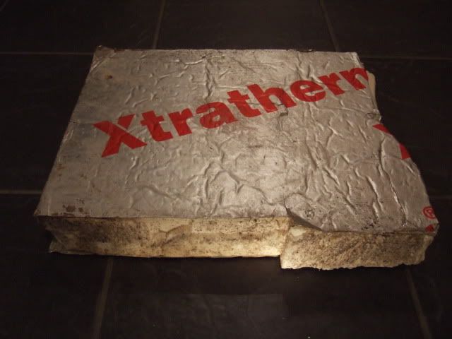
I've already collected some discarded sections of house insulation foam from nearby skips.
As I had a vague idea that I might stuff these inside the doors before adding some sort of interior door panel.


Then I remembered my Fibre Glassing Instruction DVD using foam as a mould to make a particular shape. *
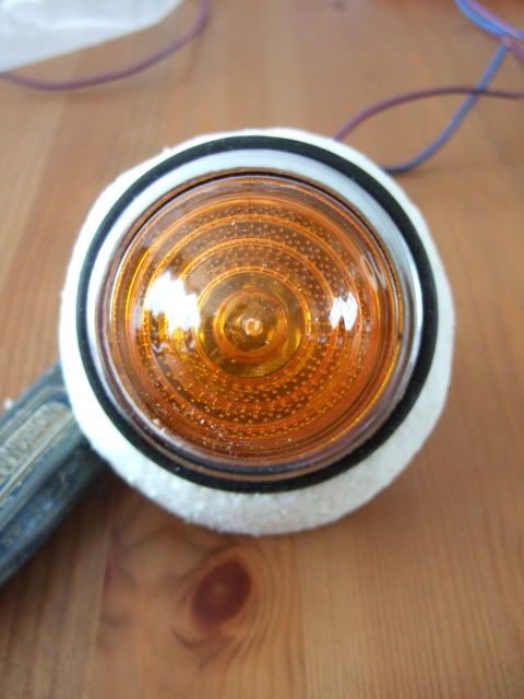
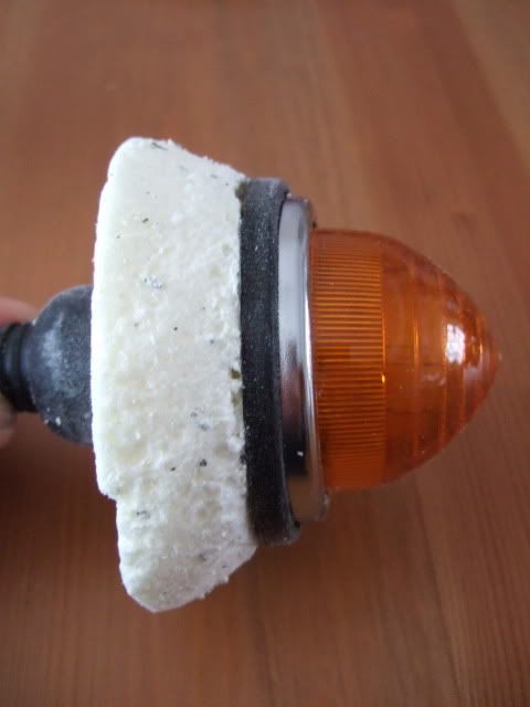
So I decided to have a go at shaping some of this foam into the basis for my indicator mounts.

* OK, technically speaking, the DVD suggested making a fibre glass mould from the foam, then using that.
But that sounds like a lot of extra work to me & I don't have any gel coat to play with anyway. :rolleyes:
So it will have a rough fibre glass finish, which be be "smoothed" on the visible bonnet side with some filer.

I just had to bare in mind a few things before I started attacking the foam with a collection of sharp "toys":
- I wanted it to match the contours of the headlights, which appears shallower above & deeper below.


- I needed to make it deeper than required, so that I can trim the back to blend into the bonnet's contours.
( Although the deepest point will still be less than an inch to keep in step with headlight mounting point. )
- I actually need both a 'left' & a 'right' mould to take account of the bonnet shapes.

So I started by cutting off a slightly over sized cube from the insulation block…


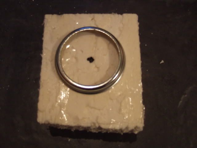
I then used the indicator's outer chrome ring as a basic guide to mark a centre hole for drilling...


I used a wood working drill bit to cut a hole for the back of the indicator to go through...


Question:
Has any body used this type of drill bit to cut through their fibreglass bodywork?
Or do you have to use the cylinder type drill bits usually used on metal?

With the indicator's rubber seal pushed in place I could use a marker pen around the outside.
Which gives me the size of the vertical surface to starting working "back" from…


At this point I sliced the block horizontally to give me the two "sides" I would need.
So this left me with two sections that both looked like this to play with...


Then I slowly, but surely, whittled the foam down into something that looked like this...


I figured in the best Sammio tradition it didn't matter too much if it wasn't perfectly symmetrical. :icon_twisted:

I now need to confirm the final location for the indicators on the bonnet.
( Ideally as close to the "red circle" mock up in the bonnet photo above).

Then I need to do is to shape the foam's flat "bottom" to blend in with the bonnet's contours.
I also must work how thick the fibre glass will end up being after it is applied over the top of the mould.
As I will need to reduce the mould by this thickness, so the fibre glass ends up the required size (touch wood).

After that, I should be ready to have my first go at making something out of fibre glass. :cool:

Observation - Working With Foam :
This insulation foam is very easy to work with, a bit like a large cheesecake.
But the stuff gets everywhere & sticks to your clothes like iron fillings to a magnet!
I think I've spent more time cleaning up the mess than on the shaping work itself.

So another inch of progress made towards the finishing line.

Until next time, take care, Paul. :)

Replies:
Mr T - At least if you have an electrical problem, chances are it will be a red wire at fault.
:icon_wink:
20 Jan 2013, 3:41pm
Nice job, any hole that big in fibreglass needs to be made by either stitch drilling and filing or using a hole saw.
20 Jan 2013, 3:55pm
Viatron wrote:
Nice job, any hole that big in fibreglass needs to be made by either stitch drilling and filing or using a hole saw.


Agreed, I would expect that wood bit to split the edges of the hole in fibreglass and leave cracks radiating from it.

I bought a set of hole saws from my local hardware store for about a tenner. They work really well, cutting very clean holes, but I did burn out a reasonable new power drill using the largest saw to cut too many holes in quick succession for the gauges :(

Planning and executing all the little mods is one of the real joys of Sammio building. You don't get such little pleasures with a mainstream kit-car. :love:
20 Jan 2013, 7:07pm
Viatron & Mr T - Thanks for the feedback chaps. :cool:

I've seen cheap & cheerful drill bit sets on ebay that look like this...


Although I'd still need to buy the odd bigger size for things like the gauges.

Is this the kind of thing you mean?

Cheers, Paul. :)
20 Jan 2013, 8:08pm
This will also work mate, i would prime foam with resin fast as it will be stronger, and when you add filler it will stick
20 Jan 2013, 9:22pm
Yep, that's the type of hole saw set although mine has them from about 15mm up to about 108mm.
24 Jan 2013, 8:29pm
Even though it was dark outside, I wanted to quickly check something in preparation for the weekend.
So sorry about the poor photos, but they are the best I could manage.

Mind The Gap - Part 1:
When removing the seat belt bracket fouling the body work the other week, I spotted something else.
The top edge of the rear cockpit body work is being pushed out by the frame rail behind it.
Not easy to see, but you can just make out the bulge in near the bottom of the hump…
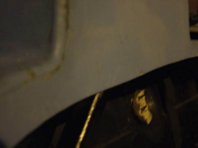
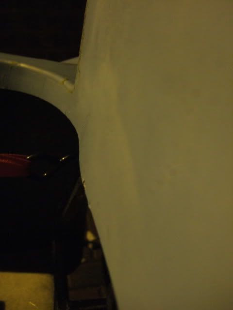


This area is effectively being "stretched" to allow the front of the cockpit to fit over the frame at the other end.
Again, not easy to see, but it is the centre of the dash area that is bulging out...
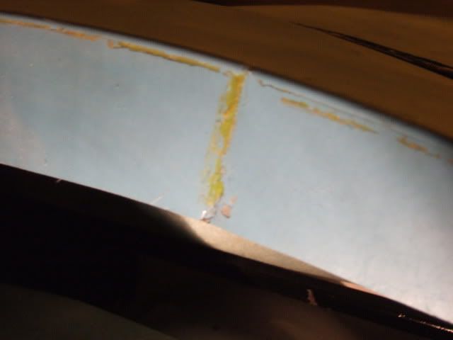
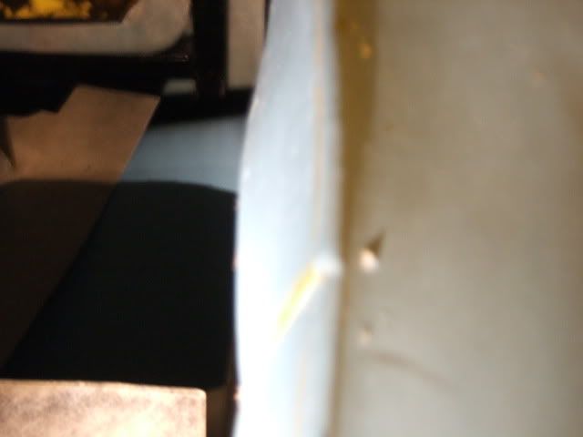


So gap between front & back of the cockpit is marginally smaller than the corresponding gap in the frame!

I'd also spotted this photo when I was searching for one of AndyP57's rear cockpit access panel…


I had previously noticed that his frame had a different design to allow the steering column to pass through.
( There is a "kink" in one of his vertical frame rails, whereas DonnySoutherner & I have straight rails. )

But what I hadn't spotted before, was that he had a revised design on the top "dash board" rail too.
So is looks like DonnySoutherner had a MkI version, I've got the MkII & Andy has a MkIII version! :rolleyes:
Which gives me some comfort that it may be the frame design, & not my fitting of it, that is the problem.

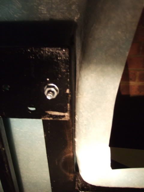
Before I start to take my jigsaw to parts of the body shell, there was one other area that I needed to check.
The body will only be able to move forward if there is a gap between the door cut outs & the frame work.
Unfortunately these touch the frame, with no real "wiggle" room to "shove" the body forward a few mm.

Driver's Side


Passenger Side
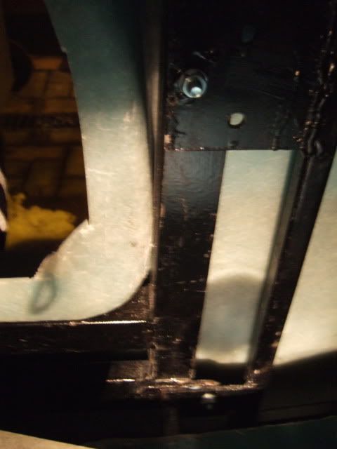


Therefore it may take a combination of alterations to both the body work & the frame to fix this.
So I will have another look in daylight just to make sure I am not missing something else.

The door cut outs lead me nicely to a related issue...

Doors - More Thoughts:
I found an old photo of one of MikMiglia's "hockey stick" bonnet braces for Mr T's build thread.
The photo was from Barry May's build and this had doors added to the original Spyder body shell…
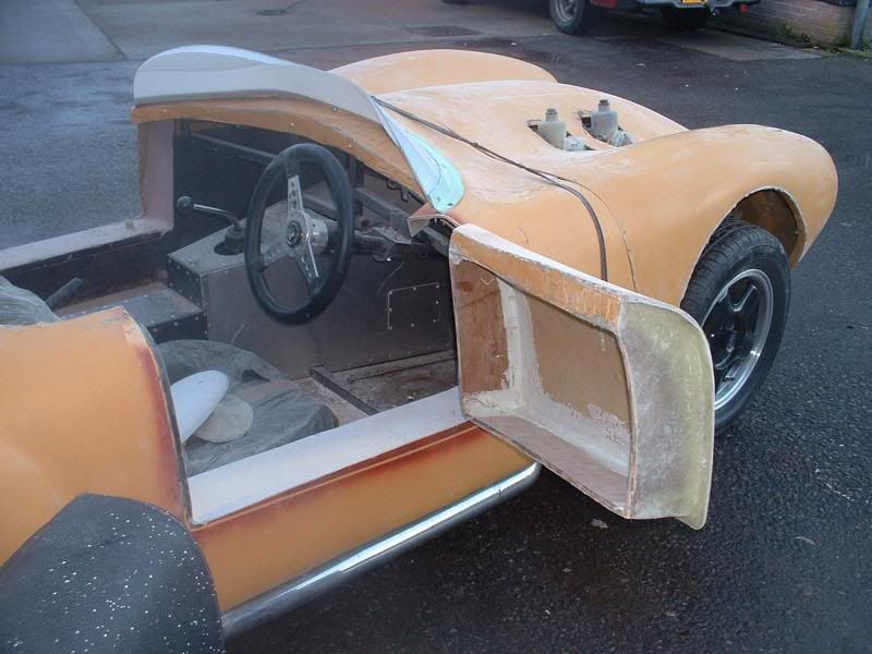


It is interesting to see how the shape of these doors & their openings differ from my Cordite ones.
The bodywork edges are very straight and only a bottom "lip" was added before this painting photo.
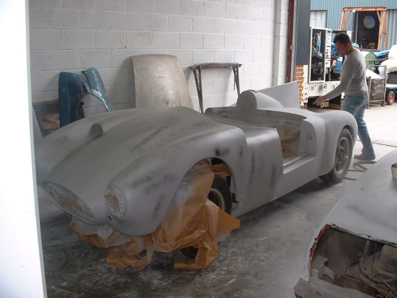


It is only when you compare the above with my first attempt at door "fitting" that the difference is clear.


Mike himself hopes to post an update on his own build shortly & I look forward to seeing his doors too.
But I've got the feeling there is no escaping some major re-working to get my Cordite doors to fit / work.
The only good news is that if the door cut outs get re-worked the body might be able to move forward.

Rimmer Bros:
Received an outstanding piece of customer service from Rimmer Bros. following my "big box" delivery.
When I finally opened the box, there were a couple of items that were not quite what I expected.
There had been some sort of technical problem with the website photos so I needed to return them.
I spoke to them on the phone, then I needed to send an email to get a "Return Authorisation Number".
So I mentioned the headlight retaining rings I'd bought in error last year when I clicked on the wrong parts.
( I only realised my error months after their normal returns policy had expired & was planning to Ebay them. )
But fair play, in a very generous act of good will, they will let me return these at the same time for a refund. :cool:
I just need to pack everything up carefully and get it to the Post Office on Saturday morning.

Whilst I'd checked all the small parts, I'd actually left the radiator bubble wrapped for "safe keeping". :rolleyes:
So just to be on the safe side, out it came for a quick check before being tucked back up in bubble wrap.


One thing that strikes me is just how light it is, I know it is made up of a large chunk of "air", but still.
I also realised just what a clever design it is too, as although it is wider, the inlet / outlet pipes are inset.
These pipes are effectively in the same place as the originals, so I can re-use the donor's radiator hoses.

I read that Mr T had accidently damaged his new radiator while working on his car which was a shame.
So in the 'learning from others' tradition I will not rush to fit this & then fit some sort of protection when I do.

Front Indicator Mounting:
While I was outside I thought I'd have a quick look at where the front indicator might go.
( Sorry I know the photo is very blurry. :rolleyes: )


It looks like the overall diameter (taking account of the rubber seal) does get in the way a bit.
So I will need to "cut in" the foam to take account the body lines from the grille & headlight.
At least I have plenty of foam to mess about with if I need to try a few options.

Anyway I'm off to do a bit more beard scratching, take care, Paul. :)

Replies:
Mikmiglia - Thanks Mike, another great tip. :cool:
Mr T - Cheers, in which case, I'll keep an eye out for a set with a wider range of sizes.