MadaboutKitcars

This is a read-only archive of the old Madabout Kitcars forum. New posts and replies are no longer possible, but every thread is still here to browse and read.

Another Cordite Is Born ...

20 Sep 2015, 5:20am
Yesterday - Part 1:
Saturday turned into quite a long and hectic day, as I tried to juggle family life with working on the car.

Thankfully the weather held, so I managed to get quite a lot done over several separate sessions, ranging from minutes to hours.

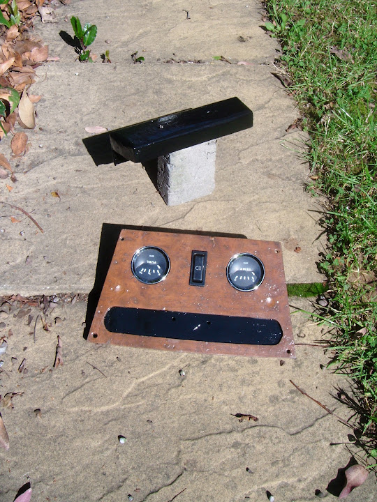
First job of the day was to leave the stuff I painted yesterday out in the sunshine.
( Just to be sure they were dry enough to play with later on. )


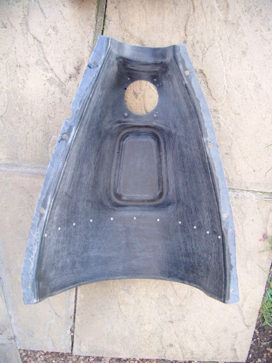
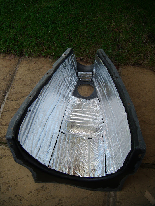
Then, in order to continue with the cockpit wiring, I pulled out the gearbox cover. :rolleyes:


Although it is not the cover I was interested in, but the heat reflective foil I bought to cover the inside.

I cut out & fitted the first few pieces.


Then finished it off.


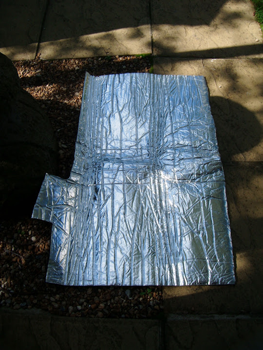
This way, I knew that the "left overs" could be used behind the dashboard to protect the wiring later on.


But while I was at the bottom of the garden I pushed the 1500 badge into position.

It is actually a tight, friction fit, but I added a couple of blobs of glue to the badge pins just to be on the safe side.
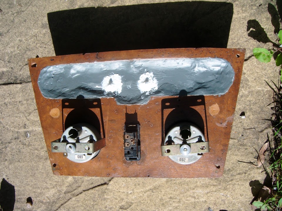


I also dug out the new metal brake light switch, which is marginally thinner than the plastic original.


I spending ages crawling around in the foot well, upside down, trying to fix the main dashboard section in place.

I lost count of the number of times I caught my back on something, banged my head, or hacked my fingers. :icon_sad:

In the end, I was so relieved when the dash was in, that I forgot to take a photo until later on.


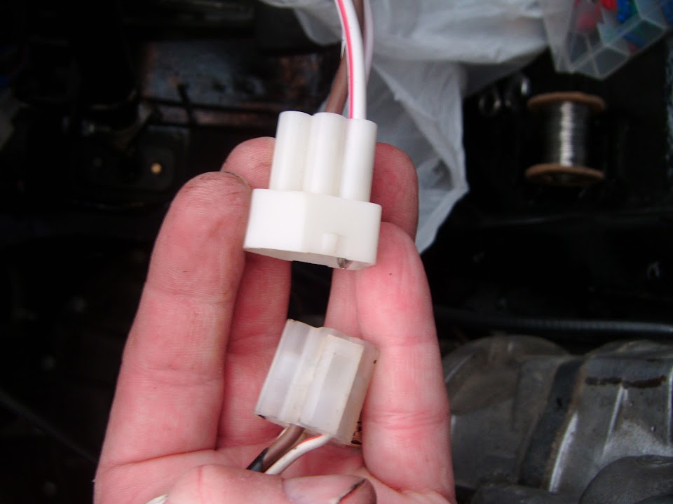
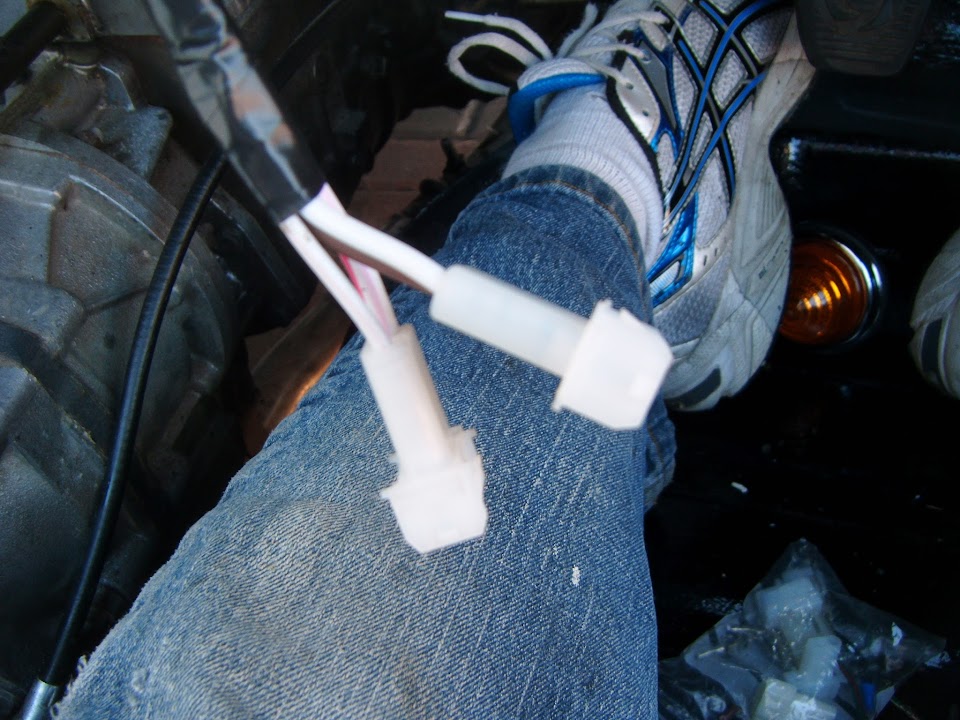
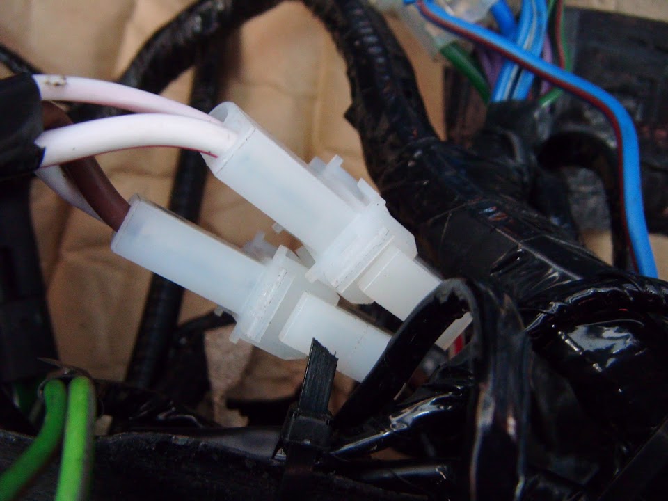
I did discover one snag, as the connection block on the new ignition wiring didn't match the old connector in the loom. :rant:


So I need to come back to sort that out at some point and I just carried on with the rest of the loom.

The more I looked at it, the more I was convinced that the relay with the clip catch wouldn't actually stay in position.

There was one hole in the dash nearby, so I drilled another and added a zip tie to help the clip do its job.


Then I wrapped some of the heat reflecting foil around the heater and the vent hoses.
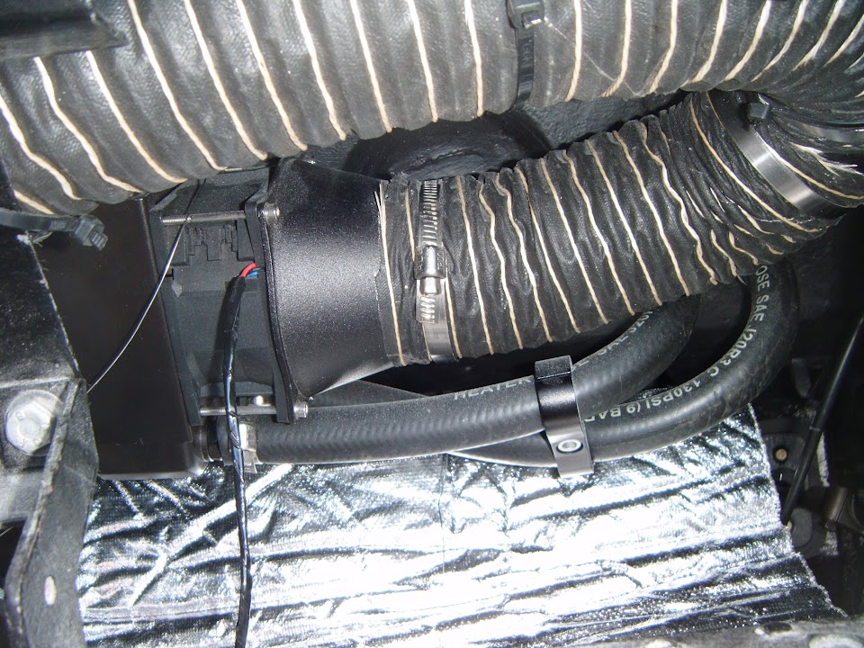


This is not a great photo, but the area behind the main dash panel has also got some protection now.
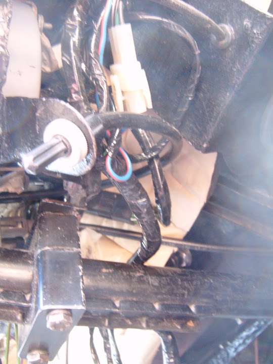


Whilst I am sure this approach is a bit OTT, and not strictly necessary, I hope it will help.

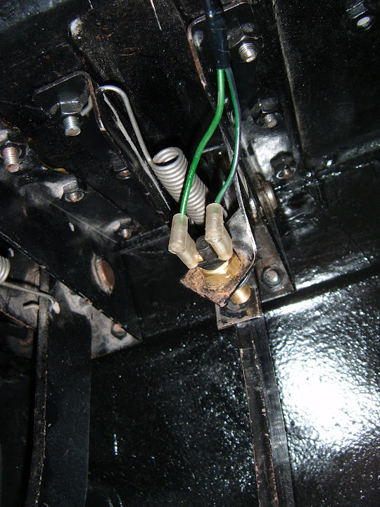
I just added a washer to one side of the new brake light switch and that went in fine.


The left hand section of the dash went in with no problems.


Note:
The wires hanging down are where the rear loom attached and these have now been properly connected and tucked out of the way.

End of Part 1...
20 Sep 2015, 5:25am
Yesterday - Part 2:
Eventually I had zip tied the bulk of the loom into position, ready to fit the centre section.


Hopefully the use of the heat reflective foil will protect this main section of the loom from being "cooked" when the heater is on.

But before I could fit the central dash section in place, I had to fix the heater control panel that sits below it into position first.


The centre section was the easiest bit of wiring I did all day.


Although fitting the panel itself turned into a complete pain, as the last screw would just not line up. :icon_evil:

So I had to remove all the other screws and start again from the troublesome corner and it worked this time.
( Excuse the run of poor photos I seem to have. )


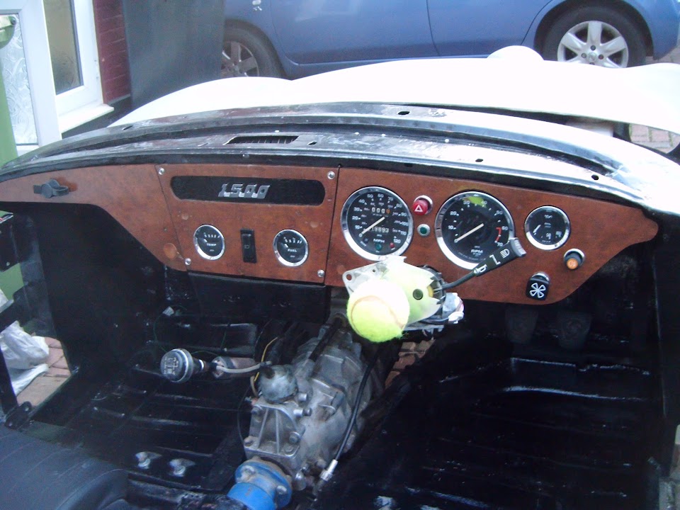
So now all three sections of the dash board were in position.


And before I packed up for the night, I couldn't resist pushing the steering wheel into place. :cool:


I just hope everything works as well as it looks. :icon_wink:

- - - - - - - - - - - - - - - - - - - - - - - - - - - - - - -

Dashboard - "To Do" List:
- Fix the mis-matched ignition wiring connection.
- Sort out the wiring for the heater fan speed switch.
- Connect the heater control dial to panel and attached to control value.
- Seal off space for wiper controls on steering column cover & re-fit.
- Attach end of choke cable to carbs.
- Plumb the heater into engine (OK, technically, that is on the bulkhead list, but is kind of related).

- - - - - - - - - - - - - - - - - - - - - - - - - - - - - - -

With a bit of luck I will get the chance to do some of these jobs later today.

Cheers, Paul. :)
20 Sep 2015, 6:33am
Its coming along in leaps and bounds now Paul.

Dash and steering wheel look the part :)
20 Sep 2015, 10:52am
A Dash, seat and steering wheel, when lunchtime comes I would be having my sandwich and tea sat in the car...
20 Sep 2015, 5:16pm
Roadster & Gary - Cheers chaps. :cool:

After so long spent trying to work out how to build this car, it does feel good to be actually putting parts back on.

- - - - - - - - - - - - - - - - - - - - - - - - - - - - - - -

Slowly Getting There - Part 1:
A slight change of plans today, as two nice days in a row saw me oiling the garden furniture before the real bad weather arrives.

I also ended up mowing the lawn and doing a number of other domestic chores, but at least I did get some car time...

I actually managed to work my way through most of the "To Do" list I posted yesterday:

Plumb the heater into engine

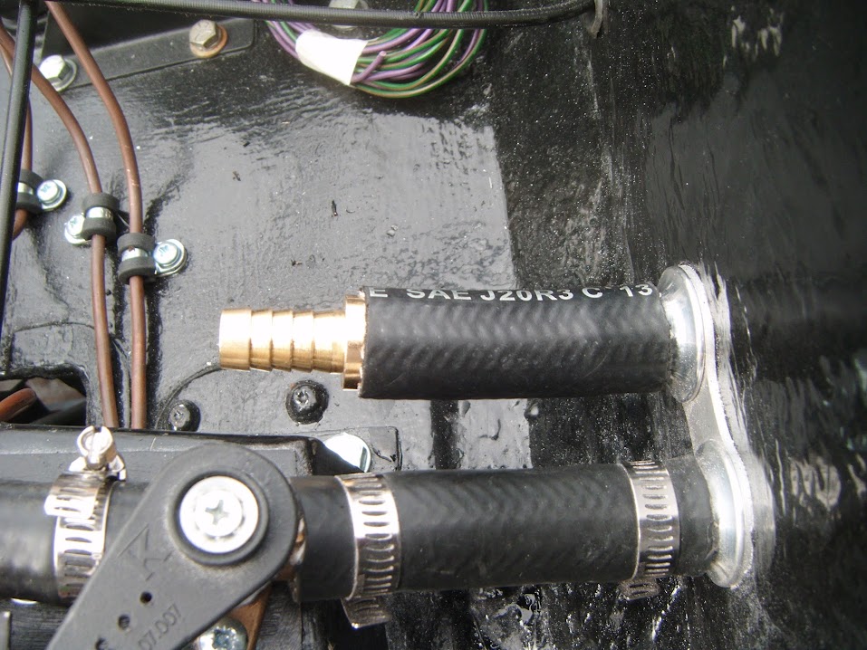
This should have been straight forward, as I had previously just by-passed the old heater like so.


I cut that hose down so that I could re-use it to connect to the heater control valve.
( Having previously double checked old photos to ensure I knew which hose went where. )


Then the wheels came off as I realised I had a mis-match in pipe sizes / hoses.

After a lot of time spent trying to make a 13mm ID hose fit a 16mm ID fitting I had to admit defeat.

So I have now ordered a reducing connector that will allow me to joint the heater pipe to the engine pipe.


As this was the first job of the day, I wasn't happy with how long I'd spent not completing the task. :rolleyes:

- - - - - - - - - - - - - - - - - - - - - - - - - - - - - - -

Fix the mis-matched ignition wiring connection

I went through my various electrical "spares", but could only find "double" connectors, rather than "fours".

So I simply used two "doubles", although this first photo is blurred.


Note:
The front indicator was there to remind me which way round the connectors needed to be wired.

With both ends changed, the ignition wires could be joined and tucked up out of the way with the rest of the loom.


- - - - - - - - - - - - - - - - - - - - - - - - - - - - - - -

Sort out the wiring for the heater fan speed switch

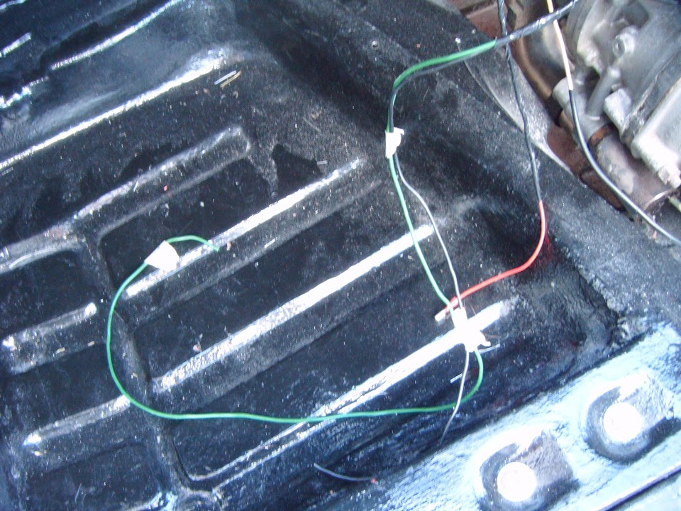
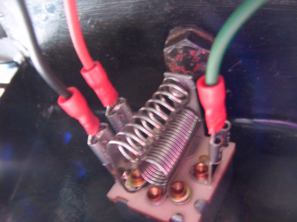
I needed to join up the wires from the loom, the wires from the heater and some earth wires.


Once I had shortened everything to the right size and added the appropriate connectors, it was time to fit the switch.

At which point, my second problem of the day appeared, which was a mis-match between the fixing holes in the panels.
( Two small holes for locating pins and one big hole in the middle. )


After spending some time hand filing the gap to fit, I then realised I actually needed a bigger hole. :doh:

Once that had been sorted out, the switch could be fitted with ease.


And then wired up.


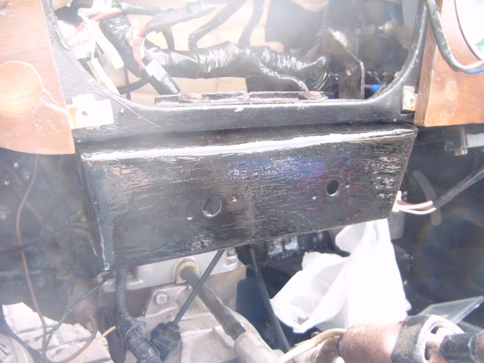
I also drilled a small hole in the metal dash board support for the three earth leads.
( Main loom, heater & heater switch. )


- - - - - - - - - - - - - - - - - - - - - - - - - - - - - - -

Attach end of choke cable to carbs

The most straight forward job of the day.


- - - - - - - - - - - - - - - - - - - - - - - - - - - - - - -

End of Part 1...
20 Sep 2015, 5:17pm
Slowly Getting There - Part 2:

Connect the heater control dial to panel and attached to control value

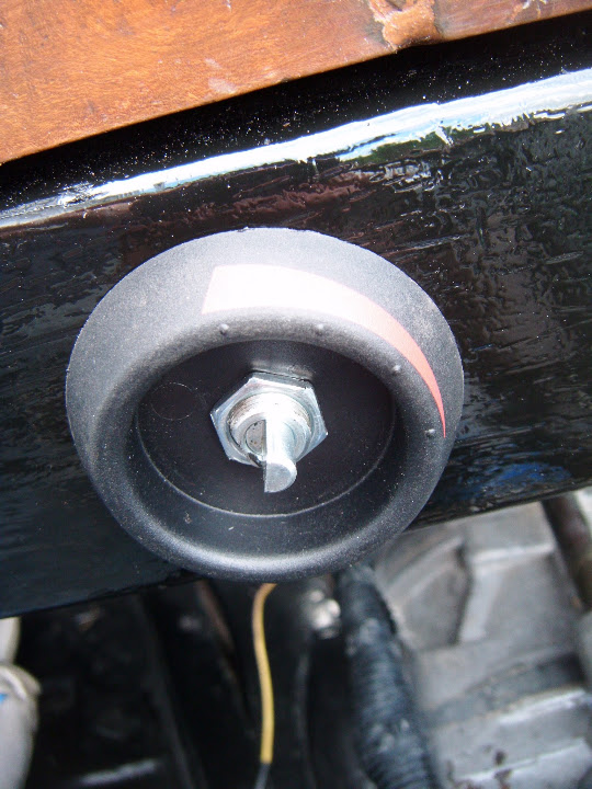
Thankfully this switch could be fitted on the first attempt.


The photo above shows the dial in the fully off position.

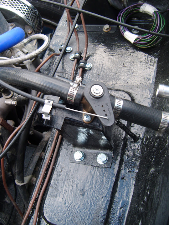
This corresponds with the cable being attached to the control valve like so.


Then as the dial is turned to the fully on position...


The valve moves like so.


For the on & off positions to tie in with the red markings on the dial, the cable would have to attach to a different hole on control lever.

However, when I tried to do this, I could not get the cable to line up nicely, so have left it as it is.
( Thankfully this build has killed off most of my old OCD tendencies. :icon_wink: )

- - - - - - - - - - - - - - - - - - - - - - - - - - - - - - -

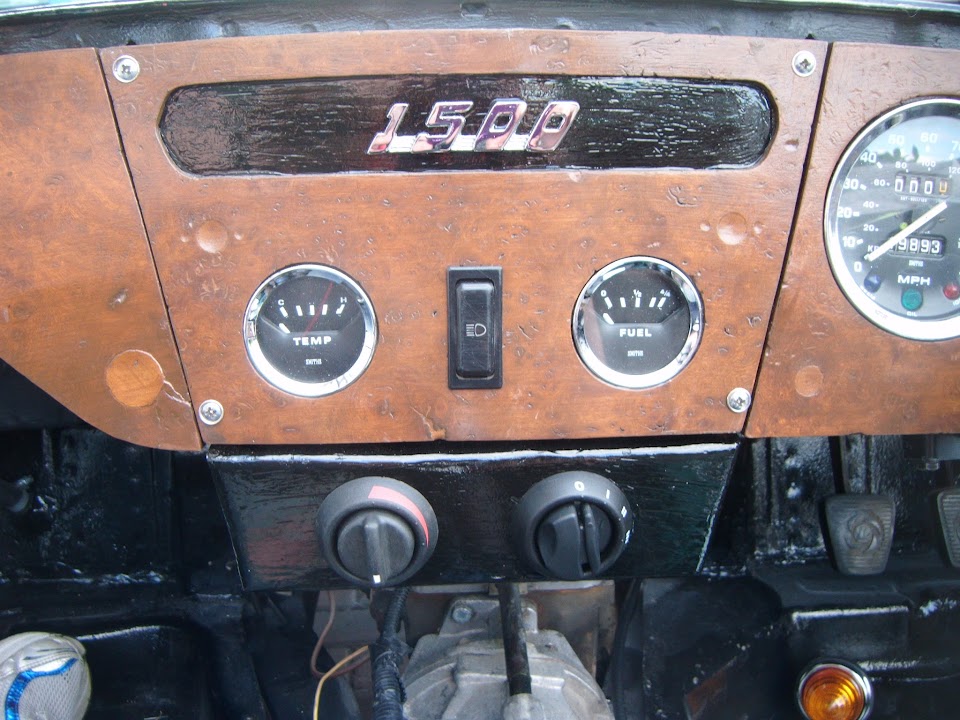
Which now leave the centre section of the dash looking like this.


The plan was to make it look like the heater was a new, modern, addition to an old racing car.
( Well that is my excuse anyway. :rolleyes: )

- - - - - - - - - - - - - - - - - - - - - - - - - - - - - - -

Which just leaves Seal off space for wiper controls on steering column cover & re-fit on my "To Do" list.

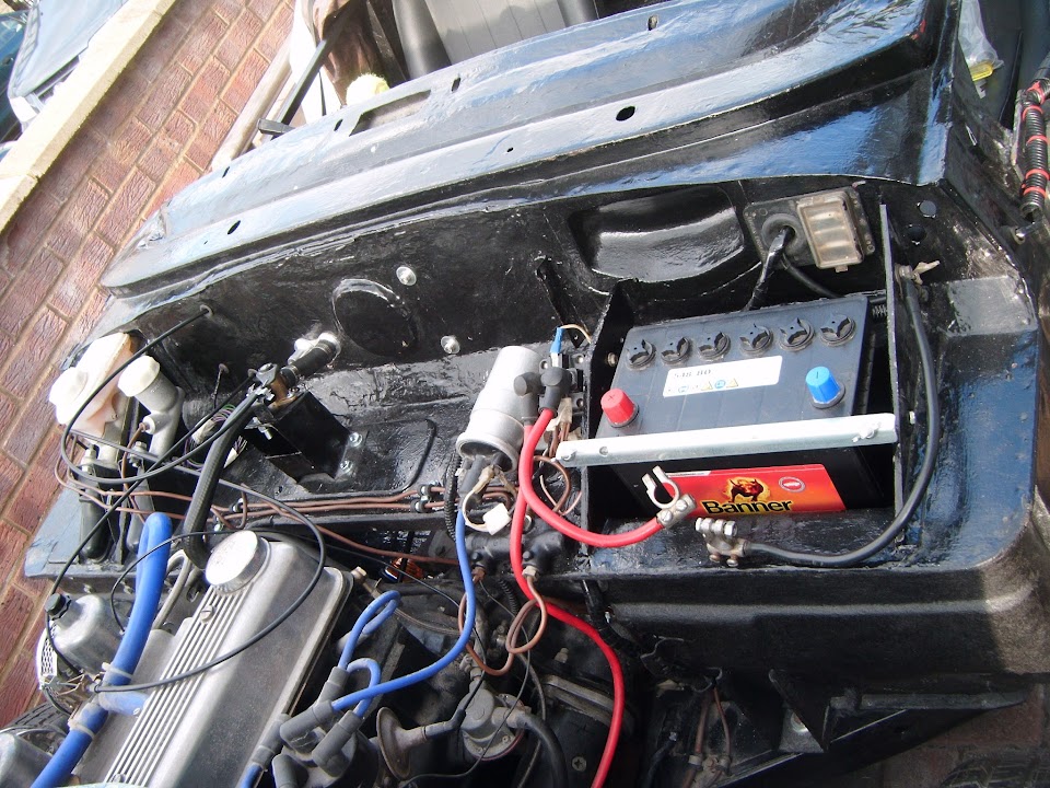
But for now, I will leave you with this photo showing how the bulkhead "shelf" is now looking.


- - - - - - - - - - - - - - - - - - - - - - - - - - - - - - -

Until next time, take care, Paul. :)
21 Sep 2015, 2:00pm
A bit of a wash out:
A combination of rain outside and a daughter off school inside, meant there isn't loads to report today.

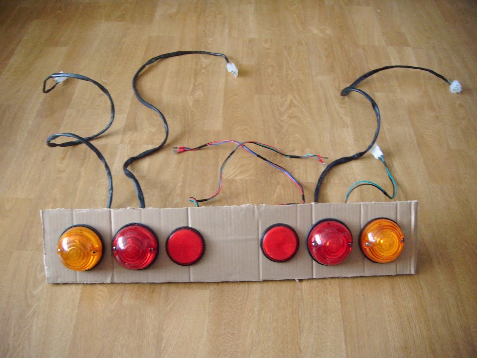
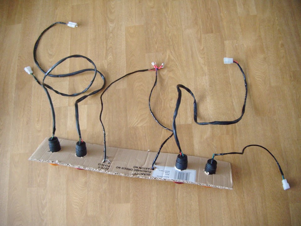
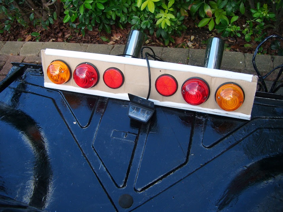
Whilst indoors I cut holes in a piece of thick cardboard based on my rear lighting template.


Then put all my rear lighting into position, so they can be tested with the rest of the Moon Rover's electrics.


I also finished wrapping up the last few wires while I was at it.


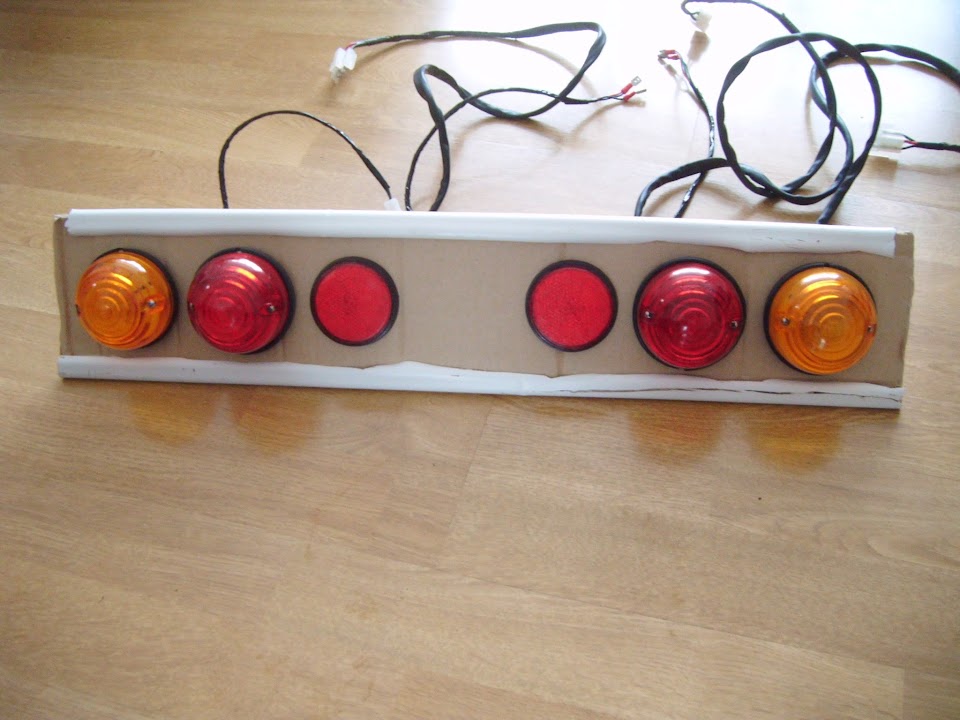
Then to stiffen up the "lighting board" a bit, I added two lengths of plastic conduit to to the top & bottom.


Which just makes it a bit easier to carry around.

- - - - - - - - - - - - - - - - - - - - - - - - - - - - - - -

I did make the tactical error of taking a chance and working outside for a few minutes when it looked dry. :rolleyes:

As I had pulled out the radiator overflow bottle I ordered years ago to replace the one that was missing from my donor.

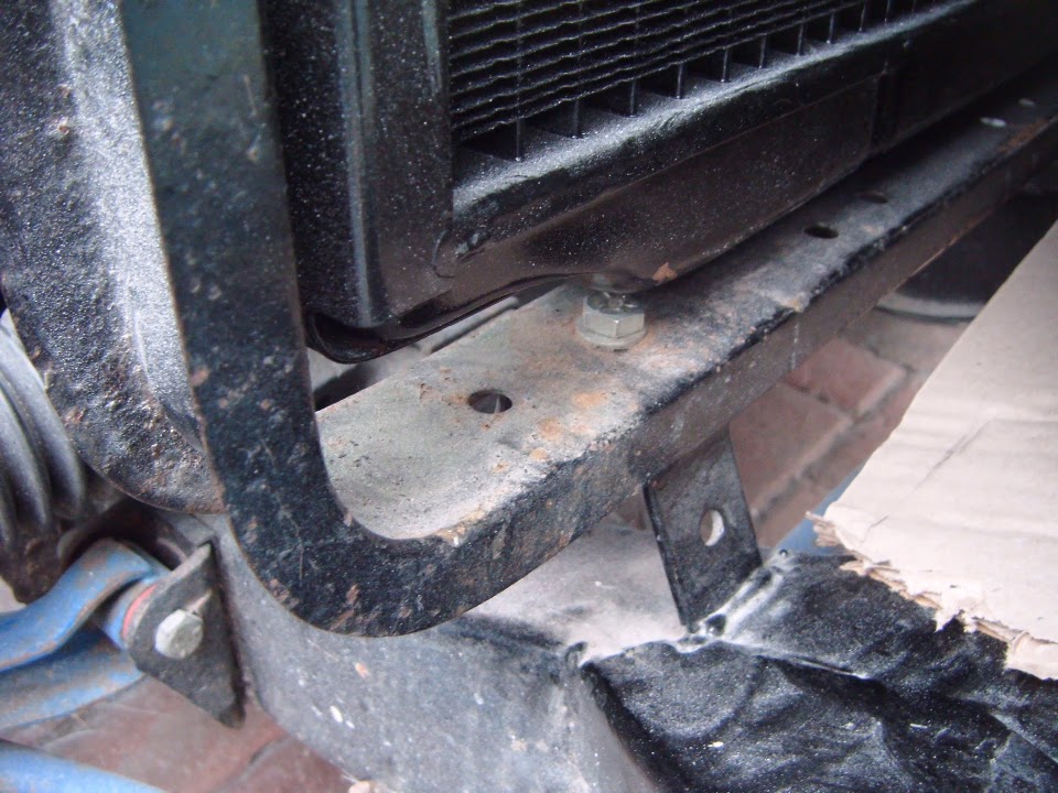
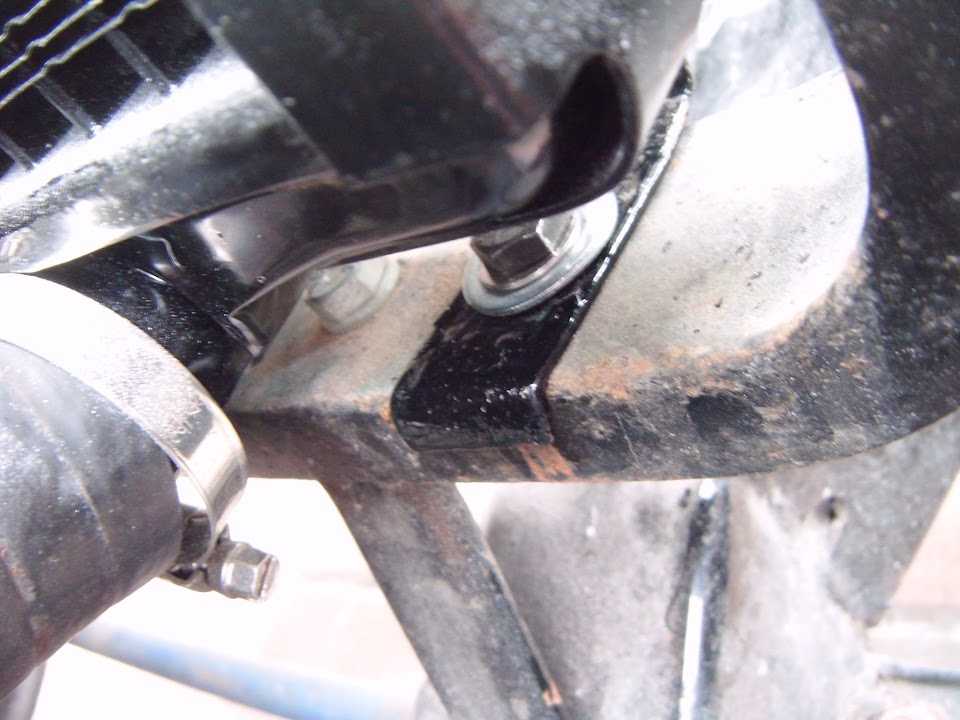
Looking at other photos would suggest this hole in the radiator mounting bracket is where it is supposed to be attached.


But no sooner had I started to tighten up the bolt when the rain returned. :icon_sad:


So the covers had to go back on and I came back for another attempt at finishing this off later on.

With the bracket bolted into position, you can see there is a lip in the bracket that sits over the radiator mount.


Then I could add the bottle and tighten up the small bolt that holds it in place.


Before swapping out the old pipe for the new one attached to the new, wider radiator.


It had actually starting raining again before I had finished this job.

So I just stayed out and got wet, rather than make 3 attempts at sorting out this simple task. :icon_evil:
- - - - - - - - - - - - - - - - - - - - - - - - - - - - - - -

Back indoors I had another look at sealing off the hole for the wiper controls.

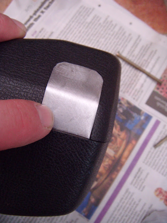
Originally, I was going to fix this metal "blank" into position.


But there is a "lip" on the other half of the steering column cover that was going to get in the way a bit.


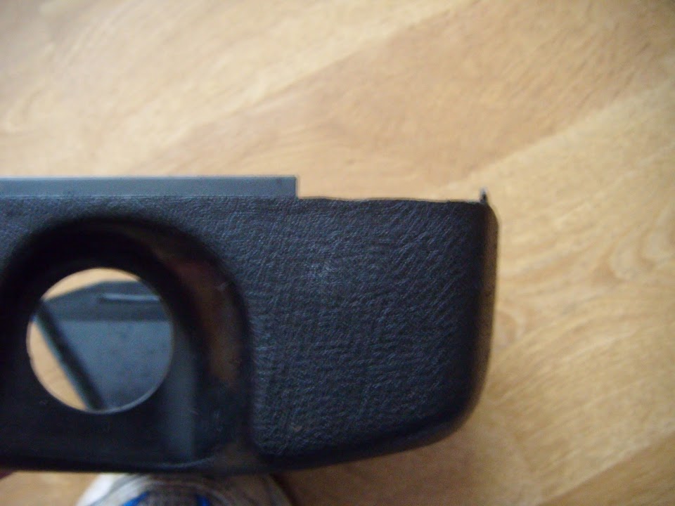
So I decided on a change in plans that saw me remove this lip completely from the bottom part of the cover.


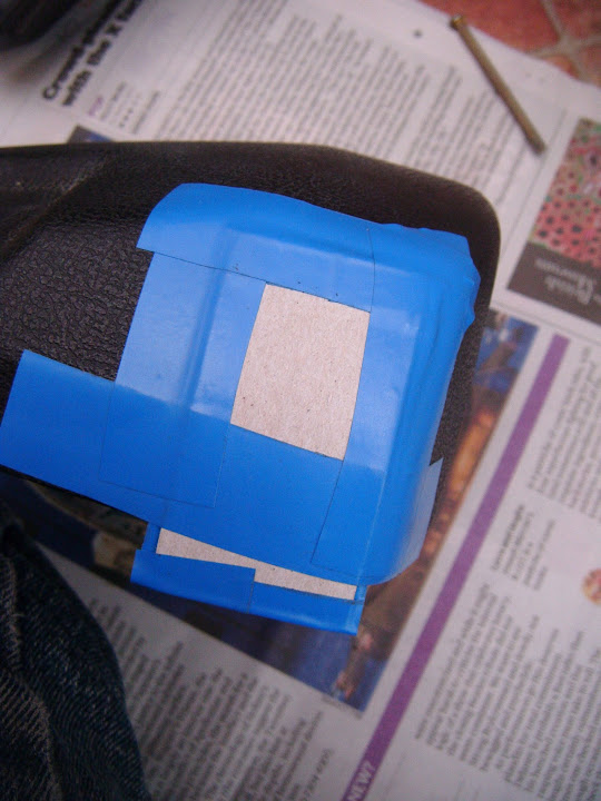
Before simply taping up the hole on the top part of the cover from the outside.


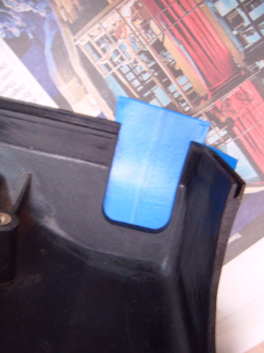
Leaving me with the area to fill in on the inside.


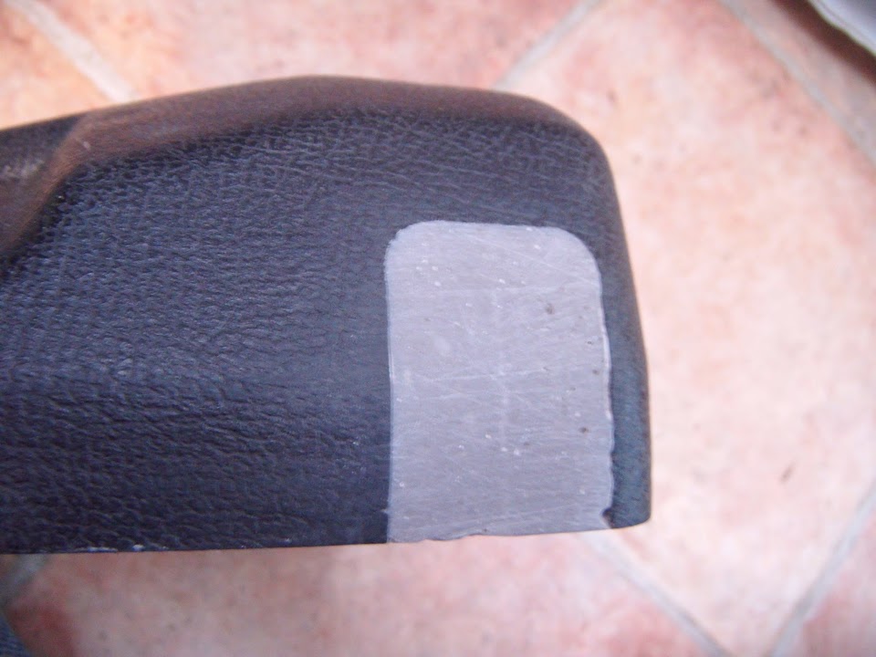
Then I mixed up a very small batch of fibreglass filler to fill in the hole and the surrounding area.


I'm sure this will require a bit of tidying up before I can paint the outside surface black to help it blend in.

- - - - - - - - - - - - - - - - - - - - - - - - - - - - - - -

As it is still lashing down outside as I type this, I'm calling it a day and getting on with some other chores instead.

Take care, Paul. :)
21 Sep 2015, 4:07pm
As always Paul I sympathise in your pain, rained stopped play from 9am here so decided I better continue and do some work for my startup business that I am in the process of beginning.

Paul I saw your post on Micks thread, I believe you might be able to retro fit the overdrive onto the steering column with a stalk. It was the same as the MGB I restored that had a switch on the gear stick an but they also on other years had it on a stalk so I just purchased used parts and relocated the wiring. Just an idea
22 Sep 2015, 3:58pm
Jones - Unfortunately, there is nowhere to attach a over drive stalk on my steering column.

I guess I would be able to mount a switch on the dash board, something like this.


That would certainly allow me to fit a gear knob that didn't shout out "Triumph overdrive".
( My mate's old Dolomite 1850 was the first car I saw/drove with this type of gear knob switch. )

Although my car will actually have a number of Triumph touches (steering wheel centre, wheel centres, etc.).

I was even thinking of adding the Triumph motorcycle logo from the bike in my avatar, like AndyP57.


So I might as well leave the gear knob alone, especially given how long my current "To Do" list is. :rolleyes:

PS
Good luck with your new business. :cool:

- - - - - - - - - - - - - - - - - - - - - - - - - - - - - - -

Plodding Along:
I just couldn't get my free time & the dry weather to line up today, but I still managed to get a few little jobs done, both inside & out...

Sanded down the fibreglass filler I had used to "fill in" the wiper lever hole in the steering column cover.


Then masked the whole thing off so I could spray some etch primer over the filler.


Made another cardboard template for the two holes required for the headlight adjustment screws.


Because I had to "fill in" the original ones I drilled many moons ago after the "cut & shut" work on the drivers wing / bonnet.

In order to ensure that my Moon Rover is working OK, I will be temporarily fitting the front headlights & indicators to the bonnet.

This will also allow me to double check the routing of the wiring loom around the front of the chassis too.

Talking of lighting, I put a coat of stone guard on one side of the rear number plate bracket, although it isn't a great photo.


Later in the day I got a coat on the other side too.


I wired up the temporary lighting board in the boot.


Note: I still need to modify the loom to switch from 3 x LED number plate lights I was planning to fit, to the 1 x bulb lighting I will be using.

Marked up when the headlight adjustment holes needed to be and drilled them out.


Note: I still need to work out the best way of actually fixing the headlights (& the front indicators) to the bonnet.

- - - - - - - - - - - - - - - - - - - - - - - - - - - - - - -

The last of the Mascots:
I am not 100% sure why I became convinced that a bonnet mascot would make a great finishing touch to this build. :rolleyes:

I think it was the fact that so many of the people who passed by asked me if it was a Jaguar, that I looked into buying one of these.


Then Ebay being the kind of place it is, I ended up with a small collection of mascots, that need to return to Ebay at some point.


Well today I had a play around with my final mascot option...


Deep down, even though part of me still likes the idea in principle, I know it would be a big mistake to fit one in practise.

Especially after watching those cars racing at the Goodwood revival, as they all looked the part without one. :cool:

So I will just go with the plan of painting a yellow band around the nose, and sticking a racing roundel on the bonnet.

- - - - - - - - - - - - - - - - - - - - - - - - - - - - - - -

Until next time, take care, Paul. :)
23 Sep 2015, 6:22pm
One Of Those Days - Part 1:
It all started off well enough as I got some black paint on the fill in panel on the steering column cover.


I also painted the bottom half of the number plate light bracket on both sides.


- - - - - - - - - - - - - - - - - - - - - - - - - - - - - - -

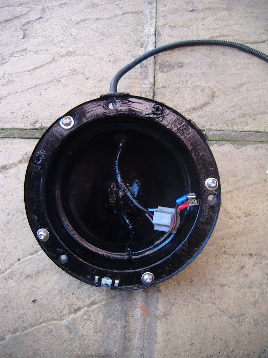
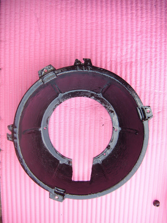
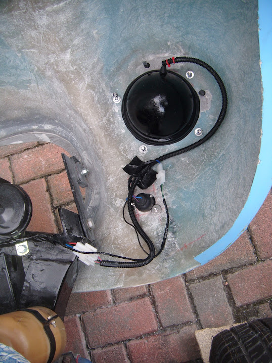
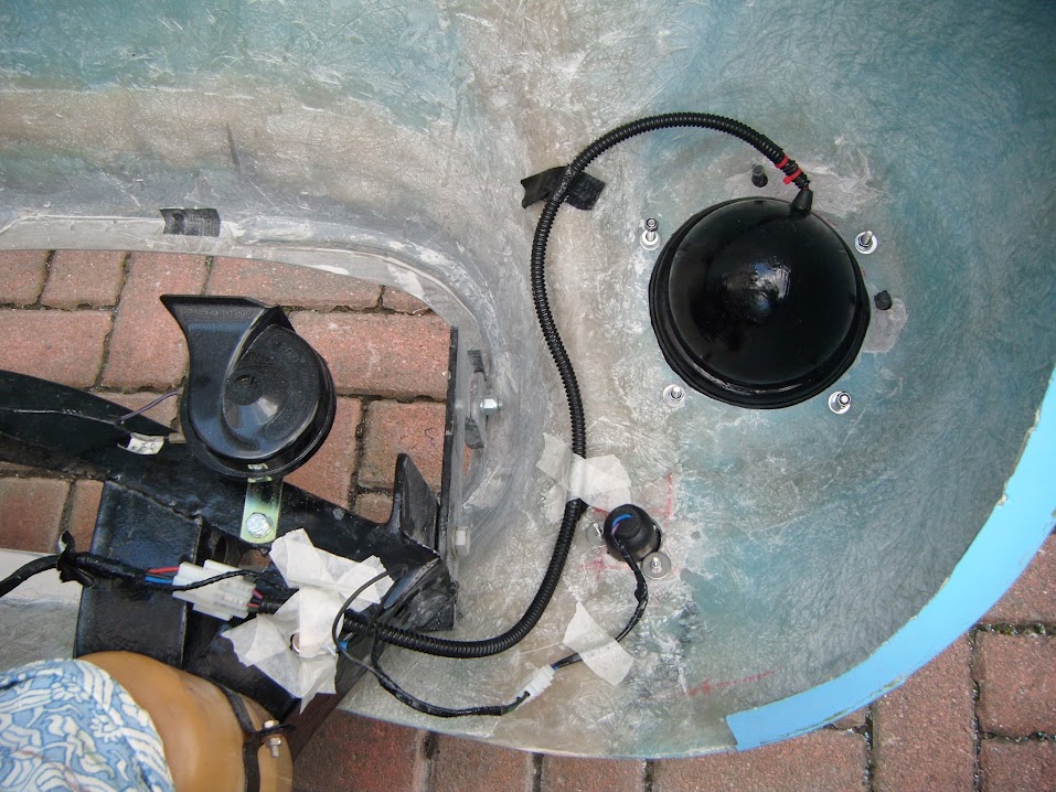
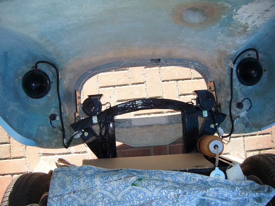
Then a sign of things to come arrived when I pulled the headlight shells out of their storage box.


Unfortunately, I had completed the wiring for one headlight before threading it through the shell. :doh:

So I carefully separated the wires from the block connector...


Only to find that the grommet wouldn't go into place unless threaded from the other side. :rant:

I was so annoyed at the fact I had to unpick the block connector at the other end I forgot to take a photo.

Eventually, the wires were secure in the headlight shell and all the connectors were back were they started.


Originally, I was going to use 3 self tapping screws to fit the headlight and had even cut 3 holes in the rubber seal.

Now I have decided to use 4 bolts instead, so I had to sort out the relevant holes in both the shell & the rubber seal.


The next small problem of the day was due to the fact the holes in the bonnet were not quite big enough.
( Due to the way the rubber seal wraps around the shell. )


A bit of filing down later and the shell on the driver's side could be pushed into place, ready to drill the fixing holes.

In order to make sure all the holes were in the right place, I did them one at a time, pushing each bolt into place as I went along.


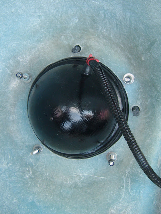
Eventually, I had all four holes in the bonnet and the headlight shell could be fitted.


Thankfully, the passenger side only required a small bit of filing in a few areas.


Then following the same steps as before, that side was done too.


Note:
By now I had marked each shell, just in case there was any slight variation from one to the other.

For now, I've just tightened up two bolts on each shell, leaving the other two bolts loose.


And this is the view from the front. :cool:


- - - - - - - - - - - - - - - - - - - - - - - - - - - - - - -

End of Part 1...
23 Sep 2015, 6:23pm
One Of Those Days - Part 2:
When I started doing the drilling work for the headlights, I was just sitting on the driveway as usual.

Unfortunately, it took a while for me to notice that my jeans were soaking up a lot of moisture. :icon_sad:

Then I remembered this photo I had seen EricHolm post on his 250SWB thread next door.


A quick trip to the Summer House later and I had what is left of the yoga mat to sit on.


I can't believe what a big improvement this made, or why I didn't think of this before. :rolleyes:

- - - - - - - - - - - - - - - - - - - - - - - - - - - - - - -

The postman delivered the reducing connector I ordered.


So I set about joining the two different sized radiator hoses together and this took ages too.

As initially I used a short section of the thinner pipe like so.


But no matter what route, or length of pipe I used I couldn't get a nice bend in the thick pipe. :icon_evil:

So I switched tactics and used a short length of the thicker pipe instead.


This allowed me to put a better bend in the thinner pipe.


- - - - - - - - - - - - - - - - - - - - - - - - - - - - - - -

Then I rigged up a glass fuel filter on a temporary basis, just so I can visually see if fuel is reaching the carbs.
( When I am finally ready to restart the engine. )


Notes:
- I need to order some new jubilee clips for these sections of fuel line.
- I also need to finalised how I am permanently going to run the fuel line in this area.

- - - - - - - - - - - - - - - - - - - - - - - - - - - - - - -

During the next task I really did lose the will to live, as what should have been a simple task took forever.

Now I know I don't have the best record of sticking to a KISS solution, but I could not work out a better way...

All I wanted to do was fix the front indicators into position. :rolleyes:

I had used one of the bolts supplied to earth the indicator.


But these three bolts were too close to "hole" required to thread the indicator wires through the bonnet.


Excuse the blurred photo, but if I put a bolt through a bit further out...


The indicator lens wouldn't sit correctly.


So I decided to use some bigger washers to move the bolt in a bit.


Initially, this approach seemed to work, so I drilled the corresponding holes in the bonnet.


Note:
Tidying up the hole is on my "To Do" list.

Then the wheels came off as when the indicator was pressed into the bonnet, the lens stopped fitting.

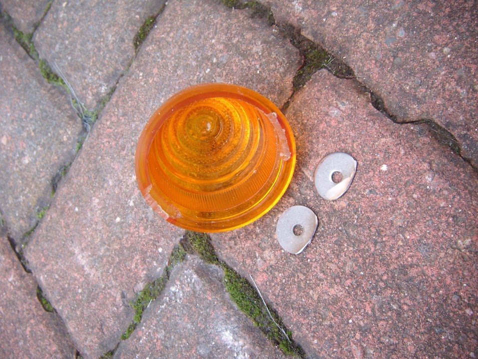
In the end I had to grind down the washers and file a couple of notches on the inside of the lens.


End of Part 2...
23 Sep 2015, 6:24pm
One Of Those Days - Part 3:
This seemed to do the trick as it all went back together OK.


So I bolted it to the bonnet.


So despite working on just this one thing for almost two hours solid, I only had one indicator in place to show for my troubles. :icon_sad:


To be honest, I just couldn't face starting on the other side, so I'll come back to that.

- - - - - - - - - - - - - - - - - - - - - - - - - - - - - - -

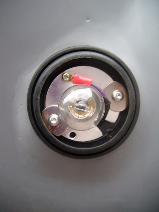
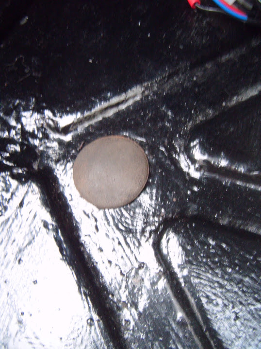
Instead I found one list "simple" job to do and thankfully, it was simple as I fitted a grommet to the boot floor.


- - - - - - - - - - - - - - - - - - - - - - - - - - - - - - -

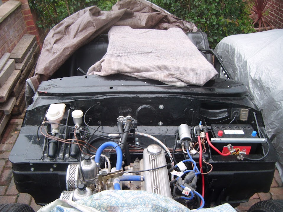
Then, just to cheer myself up a bit, I took another photo of the bulkhead, as that is almost complete now.


And that is the positive I take away from today, as despite all the frustrations, my Moon Rover is slowly, but surely, coming together. :cool:

So until next time, take care, Paul. :)
24 Sep 2015, 3:04pm
Lights, Music, Action:
Once again, the day started with painting the steering column cover & number plate light bracket.


Then, using the lessons learnt from yesterday, I tackled the passenger side's front indicator.

I will need to comeback and add some fibreglass filler to the "big hole" as one of my fixing screw holes broke through. :icon_evil:


The only good news is that I can sort all of this out after the Moon Rover testing and before getting to paint.

It was a big improvement over yesterday, as it only took me just under an hour to get this indicator fitted. :rolleyes:


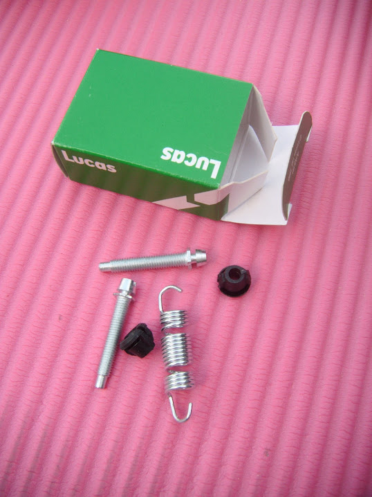
Then it was back to the headlights and the new fitting kits I had to play with.


I had already put together the various parts of each headlight.


But I had to take the inner shell off in order to hook up the retaining spring.


I then had to take the inner shell back out again and modify the hole I made for the side light wiring.
( As there wasn't quite enough room between the inner & outer shells for the bulb & wires. )


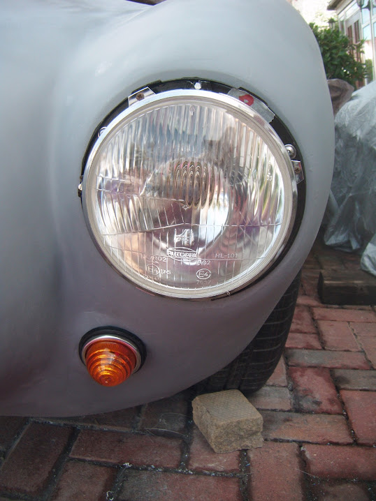
Eventually the passenger's side headlight was wired up and in place, ready for testing.


It didn't take too long to repeat the same process on the driver's side.

So for the first time ever, all the front lighting is actually fixed into position, rather than held in place with some tape. :cool:


I originally painted those headlight shells over 3 years ago, so seems like a big step forward to see them in position.
( Even if I know they will have to come off again for painting. )

I only had time for a couple of other quick jobs.

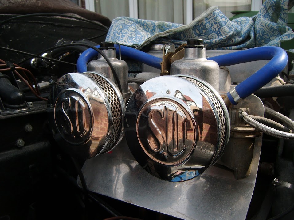
I removed the air filters, so I can clean the foam before I attempt to restart the engine.


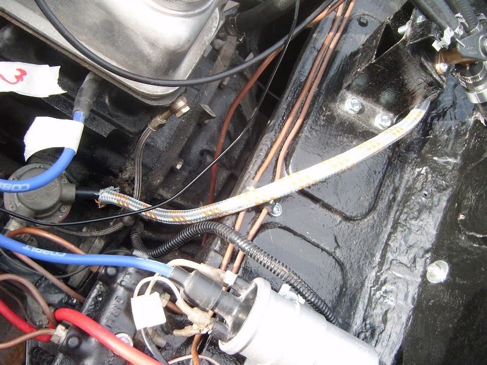
I then very roughly laid out the front wiring loom and connected a few things up.


I am planning to fibreglass a fixing point where the black tape is to help keep the wiring away from the hinges.


I just need to do a bit more testing before I commit to the final position on this.

The last job for today was to remove the masking tape from the steering column cover.


Clearly the etch primer got under the masking tape and the paint is still very shiny.

Hopefully it will look a little better once the paint has fully set and I have sand it all down a bit.

Until next time, take care, Paul. :)
25 Sep 2015, 5:27pm
Roadster - Rather than reply on Deggsy's thread, I'll say thanks on here for the offer of some extra "force" on my clutch. :icon_wink:

- - - - - - - - - - - - - - - - - - - - - - - - - - - - - - -

Frustrating Friday - Part 1:
In the cold light of day, the painted steering column cover looked even worse than it did last night. :icon_sad:

So I've sanded all the paint completely off and will simply leave it as a grey panel for now.


I attached the number plate light to the painted bracket.


Dug out the hand brake lever.


And removed the warning light sensor, as I've already removed the warning light itself from the dash.


There was something bugging me after I laid the wires out yesterday.
( As I was sure there was more slack when I tested the layout before. )


So a quick check on some old photos reminded me that I needed to lay out the wires this way instead.


Then I turned this fibreglass off cut...


Into 6 fixing brackets for the front lighting wiring loom.


Now what I should have done was mix up some fibreglass filler and stick these brackets into a big blob of that.

Unfortunately, what I actually did was attempt to use fibreglass matting to hold then in place.


What I had not taken into account was the fact that these brackets were not supported, so wanted to fall over all the time. :icon_evil:

In the end it took all of the matting shown in the photo above (and a bit extra) just to get the three brackets on one side in place.


So I had to do it all again to get the other side done and this was a seriously messy process.


Note:
Both the fibre glassing sessions had sudden gusts of wind blow the small bits of matting all over the place. :rant:

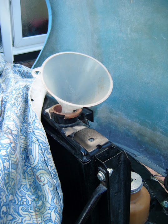
While I was waiting for that to set, I refilled the radiator.


I also refitted the steering column cover.


End of Part 1...
25 Sep 2015, 5:28pm
Frustrating Friday - Part 2:
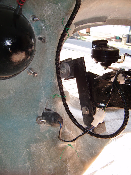
I've decided to fit a P clip to "steer" the wiring loom away from the hinges & this will also act as an earthing point.


I did the same thing on the other side, where I also had to add an earthing ring to the end of this wire.


I'd rather not talk about just how long it took me to clean up the mess I made around the fixing brackets using hand files and sand paper. :icon_sad:
( Couldn't risk putting my angle grinder anywhere near my lights. )


The only good thing was they had set solid and this allowed me to use temporary ties to hold the loom in place.

Bonnet Open:


Bonnet Closed:


I just need to add some foam padding underneath the connection block to protect it from vibration.


The only way I could get a half decent photo of the whole of the front loom in position was by standing on the front wheel. :eek:


Next Steps:
- Sort out the earthing points in the boot area for the rear wiring loom.
- Fix the wiring for the number plate light.

Whilst it was frustrating that the time burnt on the fibreglass work, meant I ran out of car time to finish those last few couple of wiring jobs today.

But overall, I am pretty pleased that I am now very close to connecting the battery and testing all the lighting in situ. :cool:

So until next time, take care, Paul. :)
25 Sep 2015, 7:27pm
All looking very neat :smile:
26 Sep 2015, 3:59pm
Paul just give both halves of your binnicle a light dusting of satin black spray you will be surprised how well it take's. Ed.
26 Sep 2015, 4:36pm
[Dr Frankenstein] "IT IS ALIVE! ALIVE!" [/Dr Frankenstein]


https://youtu.be/t64KxhCcCoo


- - - - - - - - - - - - - - - - - - - - - - - - - - - - - - -

Unfortunately, the full report will have to wait until later today, or possibly even tomorrow morning. :icon_sad:

As I now have a huge mess to clear up, a ton of other "non car" stuff to do and I stink of petrol. :rolleyes:

But despite all that, I am still one very happy bunny. :cool:

Cheers, Paul. :)
26 Sep 2015, 6:30pm
Congratulations on starting the engine Paul, one step closer.
26 Sep 2015, 9:36pm
Congratulations, it's a great feeling when it starts again isn't it:laugh:
Wiring looking very neat as well, great attention to detail..
27 Sep 2015, 8:06am
Friday Replies:

Micky1Mo - Cheers. :cool:

Whilst it was a pain to fibreglass those brackets into place, at least now the hinges won't accidentally cut the loom in half!

Ed - Thanks for the tip, but I don't have any satin black to hand, so I will add that to the "come back to later pile". :icon_wink:

- - - - - - - - - - - - - - - - - - - - - - - - - - - - - - -

Saturday Replies:

Swifty - Cheers, and it certainly feels like a BIG step forward. :eusa_dance:

Psycho Pops - Thanks Stewart and it is nice to see you back posting again. :cool:

As I was thinking about you and your car the other day, when I posted a photo of your tail pipes on Swifty's build thread.

- - - - - - - - - - - - - - - - - - - - - - - - - - - - - - -

Landmark Afternoon - Part 1:
It had already been a busy morning before I finally got a chance to work on the car.

I started by drilling some holes along the length of my exhaust support bracket.


Some of these will act as earthing points and others will allow me to zip tie the loom into position.

Although it was only after I fixed the first (of three) earth leads in place that I remembered this was "testing". :rolleyes:

So the next two earth leads were fixed to a single hole like so.


Then it was time to change the number plate wiring, originally set up for 3 x LEDs.


I had to be very careful unpicking and removing this lot.


But eventually the number plate light could be left in front of the rear lighting board, so I could see the lights from the driver's seat.


Did I mention testing? As obviously this isn't the final rear wiring loom layout. :icon_wink:


Then it finally was time to connect the battery and see if everything worked.


I even added my new key ring to the ignition key, so it was "dressed up" for the occasion.


At this point my wife & children were all out, which meant some of the testing was harder to do that others.

But here are the results:

Ignition Light - Turned the key and the red warning light in the speedo came on - Pass

Rear Lights - Noticed these were on before I had even started testing - Fail
( Decided to keep going for now and see how everything else was doing. )

Indicators
- Left signal - Pass
- Right signal - Pass
- Hazard switch - Pass
- Dash board green warning light - Pass

Fog Lights - Pass

Car Horn - Pass
( Although these worked a little too well, as I sounded like an inconsiderate minicab driver! )

Headlight Switch (Position 1)
- Side lights in headlights - Pass
- Number plate light - Pass
At this point I realised it was the brake lights that were on, not the rear lights, so I simply unplugged the brake light switch.
- Rear light (Driver's Side) - Pass
- Rear light (Passenger Side) - Fail

Headlight Switch (Position 2)
- Main Headlights - Pass

I then pulled a wheelie bin (with black sides) in front of the headlights, so I could see the reflections of the lights...

High Beam Lever
- Headlights - Pass
- Blue warning light - Forgot to check. :rolleyes:
- High beam "Flash" - Something else I forgot to check.

Sorry there are no photos, but I didn't want to waste the battery climbing in and out of the car with the lights on to take them.

Overall, I was quite pleased with these results, but there was one epic fail.

Heater Fan Speed Switch
- The fan burst into life with an annoying noise at position I, then blew a 25A fuse in position II - Fail

I'll have to come back to the problem with the fan, but for now I started trouble shooting the lights...

I removed the brake light switch and adjusted the bracket to ensure it was completely square facing the pedal.


But no matter where I set this up, the brake lights would come on before I pressed the pedal. :icon_sad:

Thankfully my family returned at this point, when I had my head buried upside down in the foot well.

So I removed the switch from the bracket (again), wired it up & operating the "plunger" by hand, while my wife checked the lights.

It only took a few seconds to realise that somehow I have ordered/bought the wrong type of switch. :rolleyes:

This one operates the lights when the plunger in depressed, whereas I need one that operates the lights when the plunger is released.
( As the mounting bracket is in front of the brake lever, which pushes against the plunger when at rest. )

Clearly, I can't fix that now, so I switched to the rear lights...

Swapping the connections over highlighted that the problem was with the passenger side light, not the loom, which was a good result.

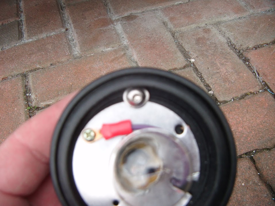
So I put a new bulb in, but that still didn't fix the problem, but a closer inspection of the bulb fitting did explain it.


Unfortunately, the bulb holder part is broken, so I've have to order another light to fix that problem.

That concluded all the simple electrical tests, but there was one more dash board dial I wanted to check...

End of Part 1...
27 Sep 2015, 8:09am
Landmark Afternoon - Part 2:
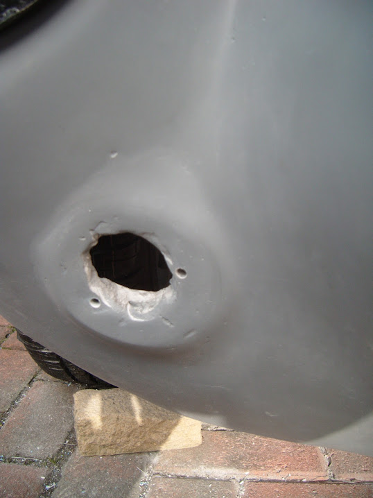
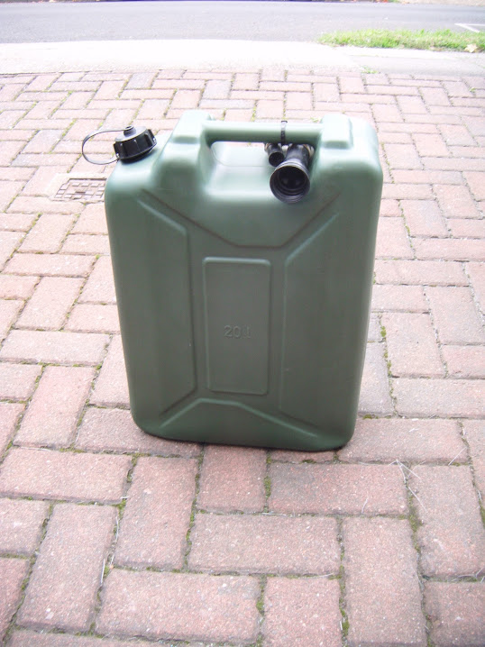
On my way back from Sainsburys in the morning, I did stop off at the petrol station to stick some fresh petrol in this.


So I found all the parts for the filler cap, removed the tape that had been sealing the tank and poured it in.


This arrangement will certainly do for testing the fuel gauge.


You have no idea how relieved I was to see the gauge slowly move over a bit. :cool:
( As I had to remove the fuel gauge sensor in order to change the direction the fuel pipe left the petrol tank. )


Note:
I was very happy at the time, but I have now had the chance to think about that gauge reading a bit more...

I put about 18 litres in, so either my tank has a capacity of 144 litres, or the gauge is reading low/not working properly after all. :icon_sad:

- - - - - - - - - - - - - - - - - - - - - - - - - - - - - - -

Engine Re-Start - Part 1:
Well I can hardly build up the suspense about how the rest of my afternoon went, given that I'll already let the cat out of the bag. :rolleyes:

But it is worth going back a few steps to put this in context...
21st July 2012 - Last time I could drive my donor car.


9th December 2012 - Last time I actually got the engine to run.


29th April 2013 - Last time I connected everything in order to attempt to start the engine.


6th May 2013 - All my attempts at restarting the engine had failed. :icon_sad:

At which point I had to strip everything down to begin my Frankenstein build, remember this chaos?


Now what I should have done, it prepare the engine to stand idle for a long time, but I didn't.

So rather belatedly, I have recently been preparing for another attempt at bringing the engine back to life.

I marked up the HT leads, so I didn't get them mixed up.


Was very annoyed to find the only way to get access to the front cylinder was by moving the alternator.


But eventually I was able to put a little oil in the plug holes and just had to hope for the best. :pray:

Either way, I was determined to take things slowly, keep checking things and not make a mess of this if I could.

Then, during the testing of the lights I turned the key the wrong way by accident and the starter motor kicked in. :eek:

At which point I figured I now had nothing to lose by seeing what would happen if I tried to start it properly.

So I removed the fan belt (as the alternator was still loose) and all the spark plugs, which were only finger tight after putting the oil in.

Then I turned the starter motor on a few times, keeping an eye on the fuel filter.

Again, I was really pleased to see this finally fill with fuel. :cool:


At which point I stopped and re-grouped, because the oil in the bores was now all over the engine & the nearest wheelie bin. :rolleyes:
27 Sep 2015, 8:10am
Engine Re-Start - Part 2:
Then I refitted the spark plugs, fan belt & alternator and double checked that everything was connected.

The noise of the starter motor brought one of my neighbours over to have a look / chat and this turned into a big stroke of luck.

As he was able to see, and point out, I had a fuel leak when I made my first attempt to properly start the car.

It turned out that in my haste to fit the new jubilee clips to the temporary fuel line arrangement I'd made a mistake.

I had accidently fitted the fuel line to the carb overflow pipe, not the inlet pipe.

I now realise that this pipe should have a drain pipe fitted (as per the front carb), but at least it was an easy mistake to fix.

I had also put a few squirts of this in the carbs before I started and kept the air filters off.


It took a few attempts before it burst into life, but when it did I was so happy, it was an unbelievable feeling of deep joy.

But it wasn't all rosy as I realised the throttle cable had come away from the accelerator pedal. :icon_evil:

This actually happened a couple of times during my attempts to restart the engine and I think there may be a layout problem.

As I have a pedal from a 1500 and a MkIV bulkhead, so the "factory" hole for the cable may be in the wrong place.


But it should be possible to fix this properly with a bit more thought & research

Going back to the engine firing, you can see the smoke in the video clip where the oil from the bores was being burnt off.

Also the engine appeared to want to rev all by itself, rather than idle, without me doing anything.

I can't say what the revs were, because by now I had worked out that the rev counter wasn't working. :rolleyes:

So I did keep turning the engine off, but thankfully it did restart every time I tried it.

The way I look at it, even if the engine runs like a bag of old nails, at least it runs. :cool:
( I will get a professional to set everything up properly for me at a later date. )

All things considered, if really was a land mark day for my build.

There will be no car time for me today, so until next time, take care, Paul. :)
27 Sep 2015, 10:10am
It's all coming together nicely :dance:
28 Sep 2015, 8:39am
It seems ages since I read your thread Paul, and my oh my, you have come a long way!

I can identify with you on the front indicators, as my two had almost identical problems as you did.

One of my drill-holes broke though, and I was so peed off at the time, I just put a washer on the other side of the self tapper and its been like that ever since.

Congrats on the engine start. You'll soon be done!