This is a read-only archive of the old Madabout Kitcars forum. New posts and replies are no longer possible, but every thread is still here to browse and read.
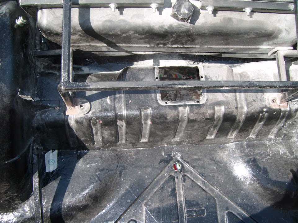
I don't know how accurate the info is, but I saw a report that Waxoyl will eat into and damage GRP - so maybe care has to be taken on the chassis/body interface that no waxoyl gets on the GRP.
The Miglia frame is simpler than the original S*mmio one , a little too simple in my opinion . Mike was an ok laminator but he isn't a fabricator and , I felt , the frame in the Miglia demonstrated this quite well ..its a bit lacking in strength in my opinion ...but this factor probably means it accommodates seats better .... I would take the opportunity to brace the frame with some triangulation whilst you are building the car ...
Thank you for the advice. Do you mean to add the triangulation at the area below the doors, from back to front?
I am going to add the centre section along the prop shaft, from front to back for sure and strengthen the area for the steering wheel column.
Thank you Mr T. I am planning to use the doors supplied with the body though, so I won't be able to replicate the Spider's frame, but I will have to try to improve my frame at certain places.
We discussed the frame previously in the thread but it was related mainly to the steering wheel column mounting reinforcement.
Not sure where exactly Gary suggests to add the triangulation, as the Formosa's frame is quite different from Miglia's. Only way I could do this is to modify the doors by reducing their height I guess , if that is the area he refers to?
That is coming along very nicely matey! can't wait to see the moon-buggy stage as that is always a huge milestone
In case it's of any help as far as frame strengthening is concerned, i added a reinforced the central tunnel area on my frame made from steel box as i'd originally had flex from my handbrake area on the Sammio until i re-enforced it, so i thought I'd address that straight out of the blocks this tine.
Then rather than adding to the side frames with triangulated steel (as i wanted working doors as well!) i decided to do the rest of the strengthening with the alloy panelling and it's supporting alloy framework.
With my old v.hard front suspension i've very little body flex or creaking so far, so i'm happy with how it turned out.
davecymry - thank you very much for your comments and the advice mate, very helpful.
I can't wait to reach moon-buggy stage but I'm getting there (slowly :smile. I am a bit slow as I can't work on the car regularly, but mainly due to the lack of experience, and sometimes have to research a lot and re-think some ideas to not make silly mistakes. This slows me down and for that reason I appreciate all comments and advice. I am pleased how it is all turning out and thank you and all the other people that are helping with invaluable advice.
I was thinking about the frame reinforcement for the last few days and came to the conclusion that if I want to keep the doors, I will not be able to do much in that area.
This only leaves me with a few possibilities, and adding a prop shaft tunnel is definitely the most important one, so I will do that for sure.
I was thinking to reinforce the areas in front and behind the doors on each side, but I would not like the frame to become too heavy - now you have mentioned that the internal paneling adds quite a fair bit to the overall stiffness and the strength, which makes sense, I will first add the middle section and then see if I need to add any further reinforcements in other areas.
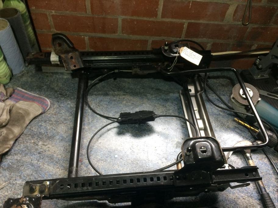
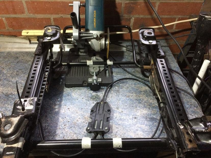
More progress, so here are some photos. When I had a trial fitted the seats, I have noticed that I have to raise them quite a bit to be able to see above the screen. I decided to do an experiment and I have bought two 2nd hand adjustable seat bases with the sliders, which can also be height adjusted. They can also be electrically adjusted apparently, but I am not bothered with that to be honest. I just want to make sure that I can pass the M.O.T and to be able to see above the screen.
I have removed two back mounting plates, as they were pointing in (for my purpose) wrong direction and would not allow the seat to fit in the floor pan.
...no way back now...
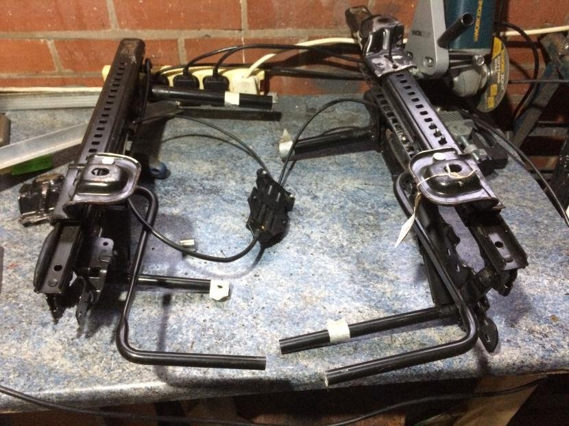
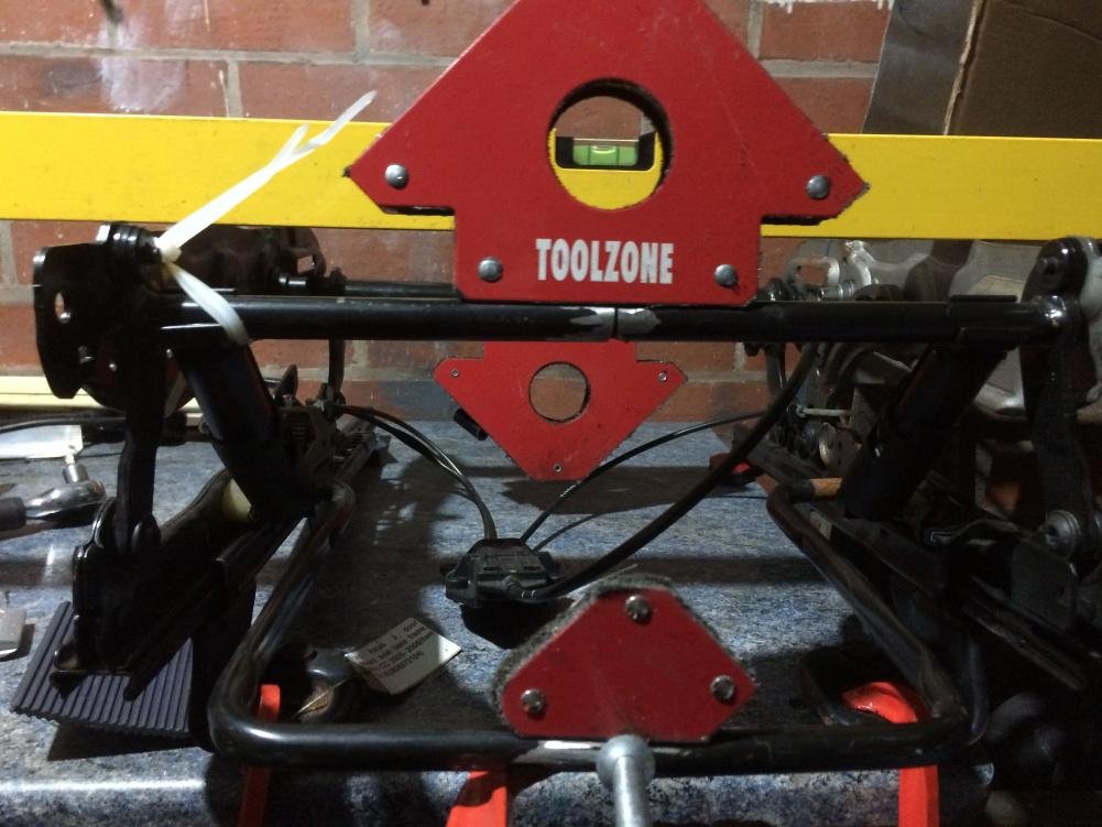
I have narrowed the seat for 6 cm and just tacked them for now.
They fit very nicely now. There are plenty of possibilities to use my MGB back part of the seat and attach it to this base. I will use the original foam and the vinyl from the MGB seat to cover this new seat base.
I could not trial fit the body this weekend to further check the clearance on top, but I can now move the seats more towards the centre, and if I have to cut into the body to make it all fit, then so be it...
I will post further update on seats when I trial fit the body.
As I could not trial fit the body this time, I have continued with welding the additional bits on the frame.
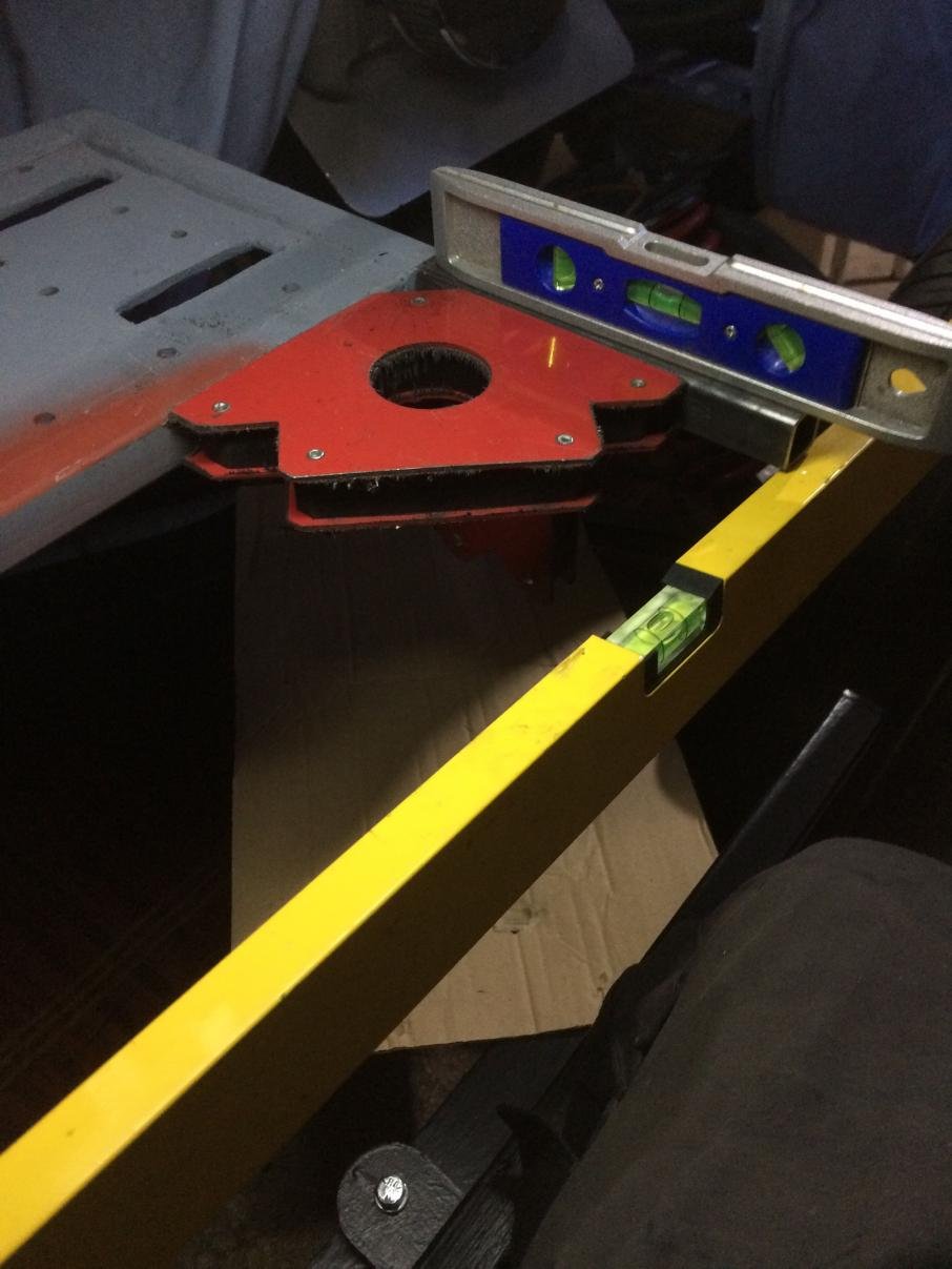
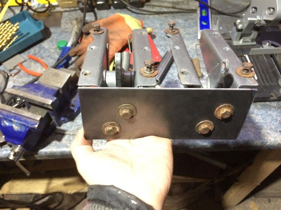
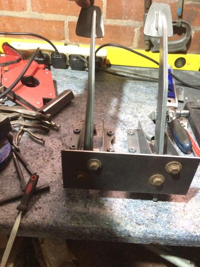
I have added the reinforcement to minimize the movement of the pedals plate and done the same on opposite side.
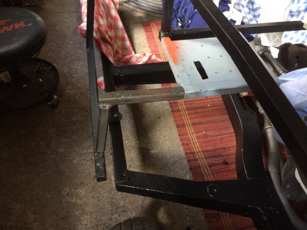
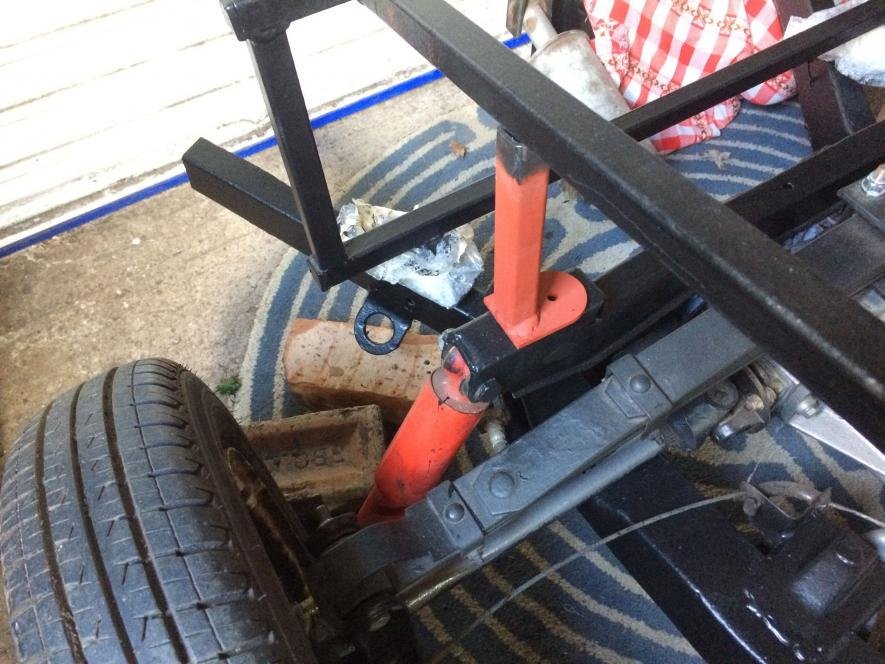
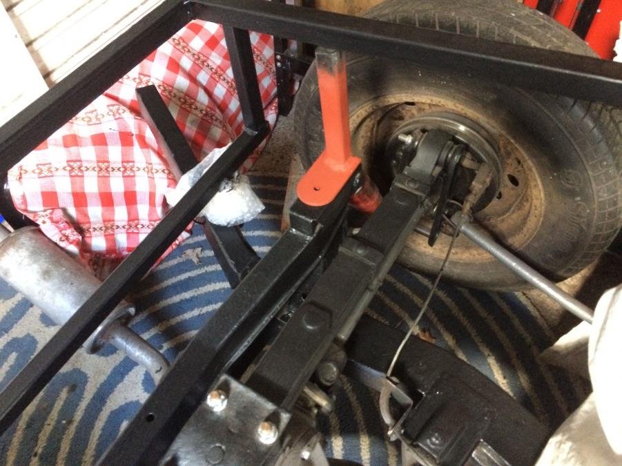
The frame was delivered without the mounting points to the back of the chassis, so I've added those too. This will make everything a bit stiffer and help carrying the weight of the petrol tank when filled with the fuel.
I will weld it all to the frame later on, as I would like to take the frame of the chassis to be able to turn it upside down to make it easier to weld the bottom side of all added bits.
I have also prepared the back plate for the pedals. This will be welded below the pedal plate as the bottom part of the bulkhead will be a bit further away than the original, as the square tubing is surrounding the plate. I will attach the back of the pedals to the bulkhead too using some tube spacers.
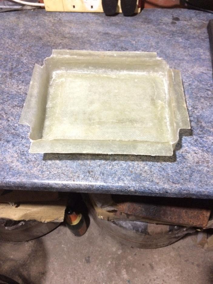
My lowered battery tray has cured now and I have peeled it of the mold. This is now ready to be inserted into the top part of the bulkhead and glassed in when I am ready to do final bonding of the fiberglass bulkhead to the steel frame.
… The frame was delivered without the mounting points to the back of the chassis, so I've added those too. This will make everything a bit stiffer…
Deni – That is definitely a good call, as there were rear “feet” on the original Cordite framework.
( Although I had to shorten mine to accommodate the Spitfire rear arches I used. )
Also, it looks like you have reached the ‘fearless’ stage of cutting and welding now.
Paul L - yes Paul, it looks I am in the 'fearless' stage as I am getting more confident in my abilities. I just have to make sure that I don't progress too far, i.e. the 'reckless' stage
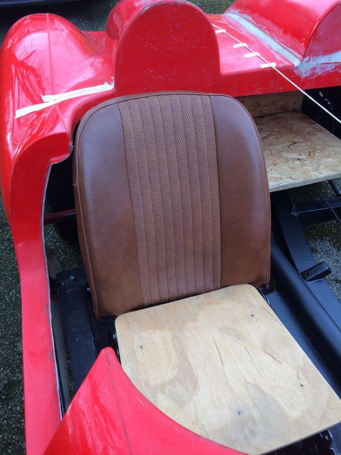
Just a quick update. I have had a chance to trial fit the body this weekend. I am very pleased that I will be able to use my MGB seats. Narrowing the seat base worked out and the upright part of the seats fits without need to cut the body. I will tweak this further when I bond the body onto the frame, but it is good to know that I can now commit to these seats.
The angle of the upright part of the seat is adjustable and it can be folded too. The seat base is fully adjustable too (height and back/forward) and pictures show the base of the seats at it's highest position, so there will be enough space for head rest cushions too. eace:
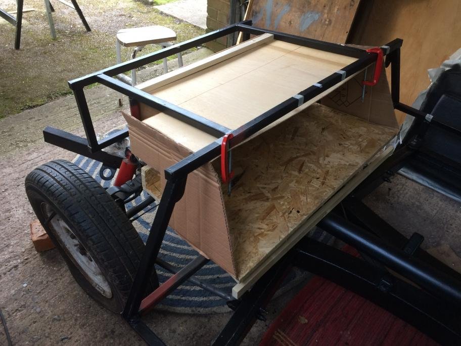
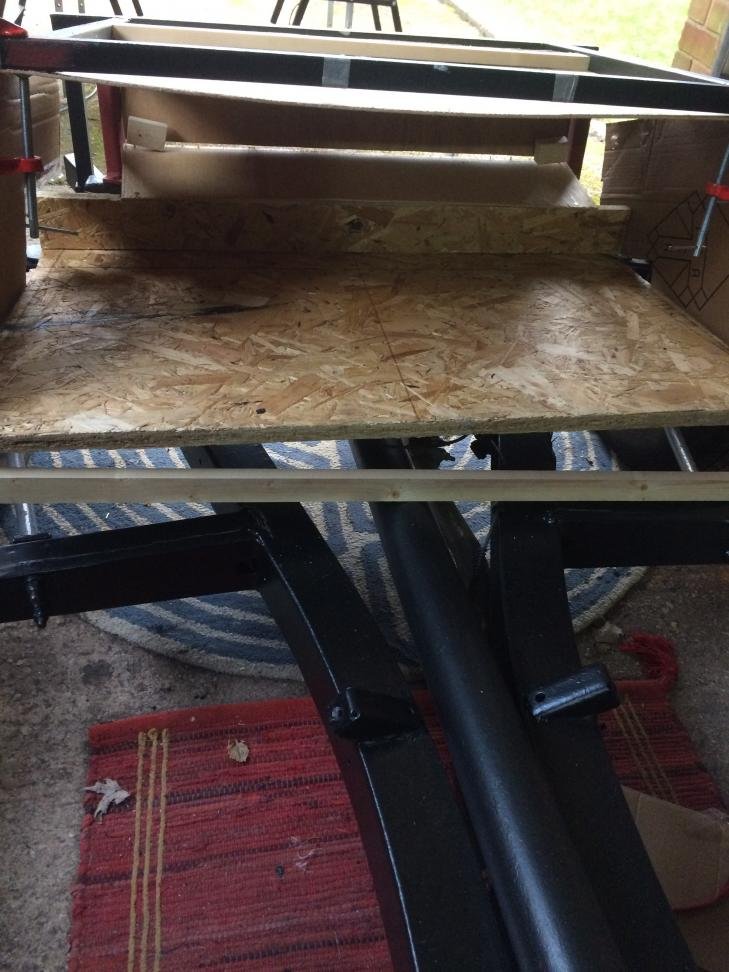
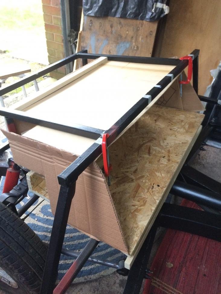
Looking at the photos it seems that I did not do much last weekend, but I did lot of measurements, drawings and head and chin scratching to decide (figure out ) what to do next and how, which also need to happen I suppose....I have made a mock up of the compartment behind the seats. I will make a wood template and make a fiberglass copy of it. Still need to finish the mock up, as I keep changing it to maximise the space. I would like to fit a spare tyre in it and a small bag of tools/things, jack etc.
I am trying to extend the box to go over the swing spring. I will make sure I make access to the spring to diff mounting area if it is necessary to access it in the future.
I will also make it a bit longer at the bottom. When I've trial fitted the seats I noticed that there is available space behind the seats, even if they would be in their position furthest at the back, so the back bulkhead can also be angled rather than straight, which might look good actually...to be continued...
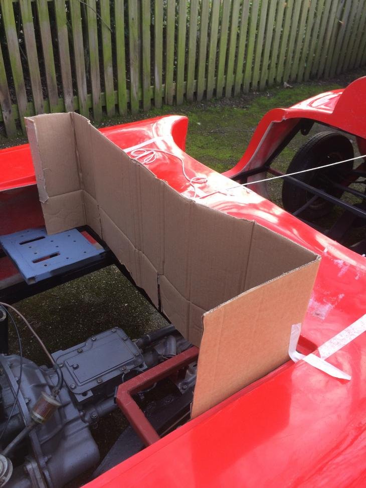
I have also traced the line of the body curvature at the back of the bonnet area to make a template for the upper part of the bulkhead. This will also be made in fiberglass, glassed together with the rest of the bulkhead and bonded to the body later.
Great that you can use your MGB seats, they are very comfortable.
Leave yourself plenty of space around the rear spring as it's a bugger of a job to remove it if you need to (make sure you loctite the studs into the diff and use new locknuts as there's a tendency for the studs to come loose if you don't).
I found the space behind the seats very useful for 'hand luggage', a towel to wipe your face when it rains, a bottle of water etc. A sealed in, sloping bulkhead might look cool but the space is too useful to lose imho.
Thank you Mr.Towed. Yes, I am really chuffed I can use these comfy and, in my opinion, good looking seats.
The panel on top of the swing spring will be removable, if I decide to make the box so deep. I will make sure I put some loctite on the studs, thanks for the tip.
The angle where the back bulkhead will be looks greater on the photo than it really is, so even with the slope I will still have some space behind the seats.
I will try to make it like this, just to see how it fits/looks, and if it does not work out I'll trim it back.
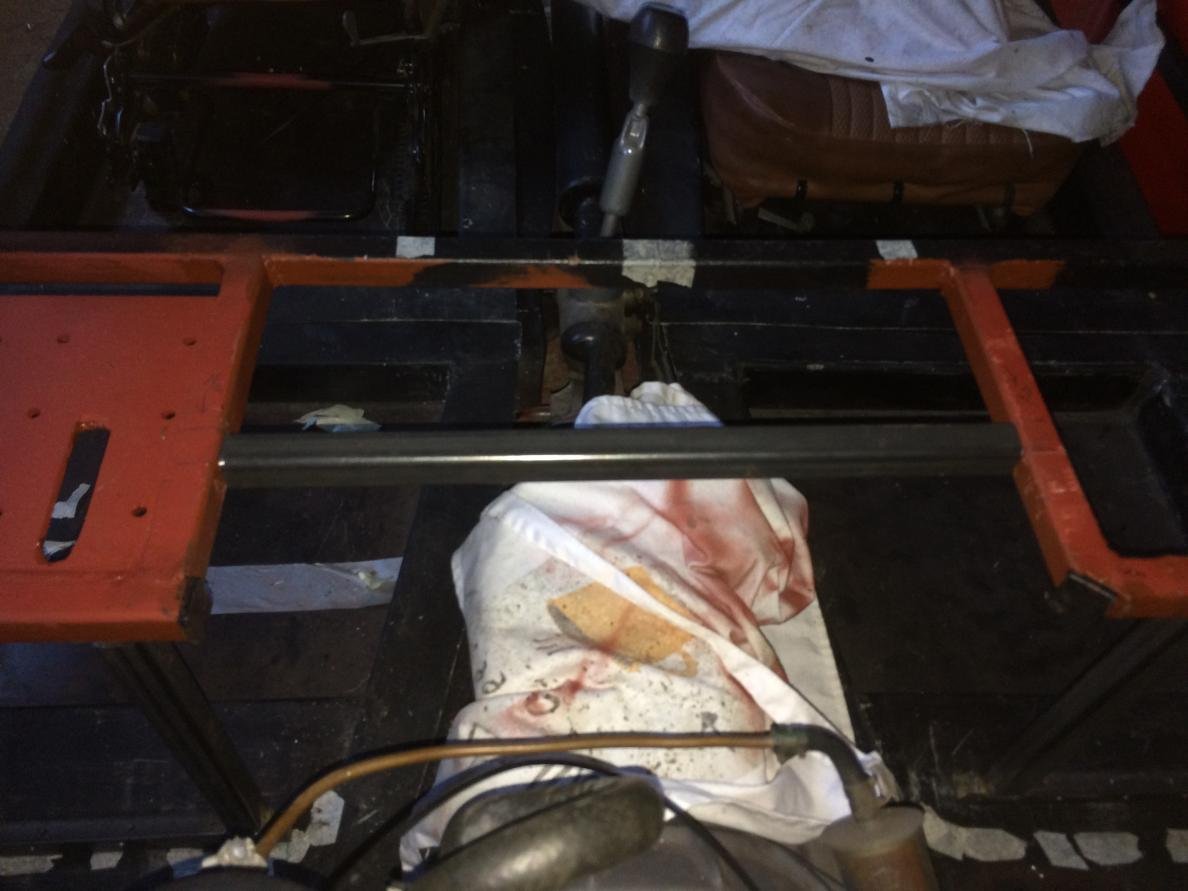
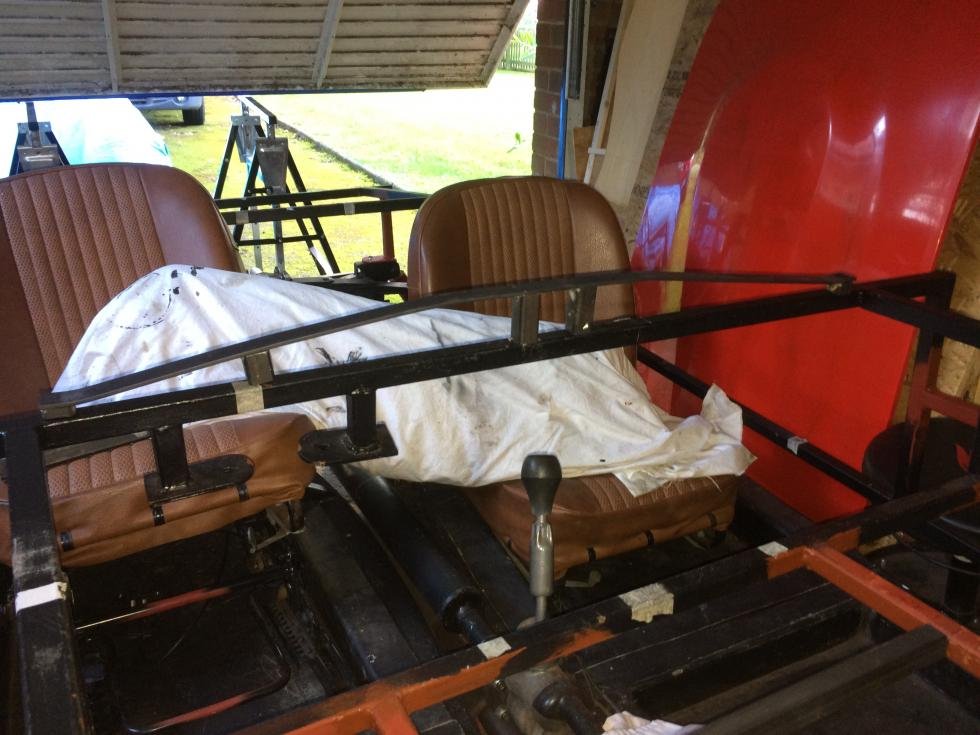
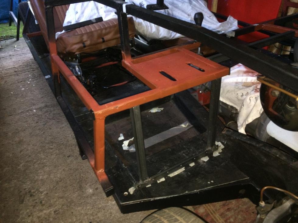
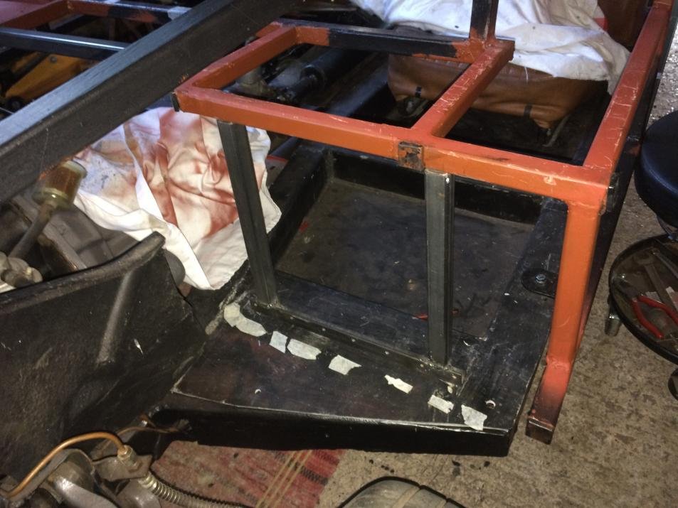
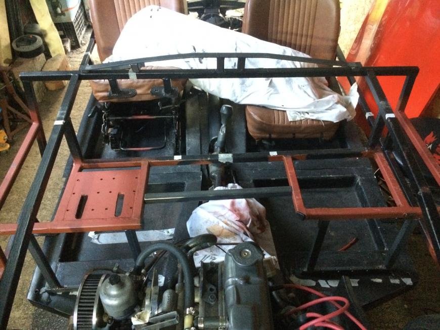
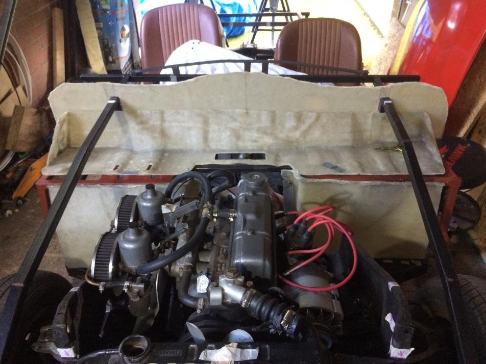
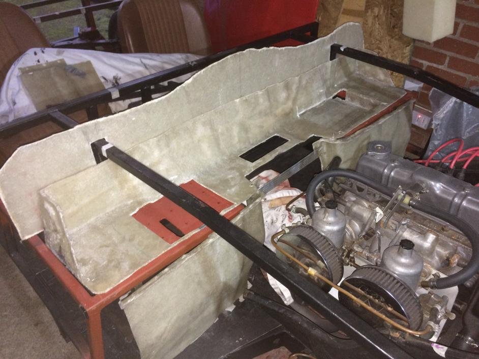
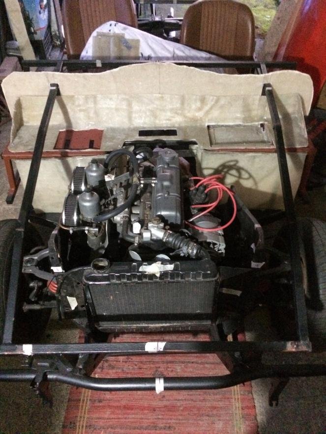
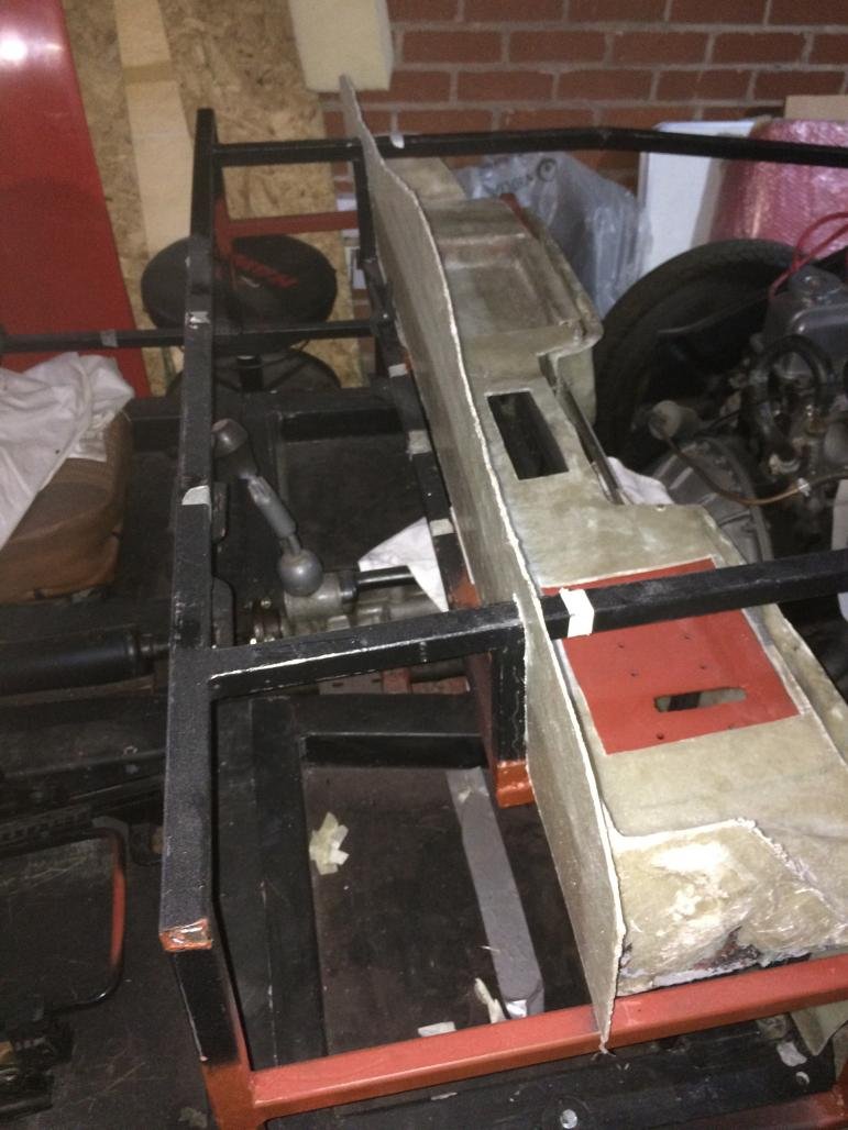
Finally I can continue with the build… I have made more modifications on the frame, so I think the front side is done now. I will only add another L shaped brace in the middle of the top bulkhead rail to connect it to the bottom rail (marked with masking tape).
It's all just positioned on the frame at the moment and I just need to finish welding it to the frame. I did not have time to do it this weekend, after measuring and fabricating the parts - I have to do it slowly and generate as little heat as possible, as I have filled the frame with the wax to protect it from the rust at the very beginning of the build...
I am happy with the frame modifications at the front, so I can continue with placing fibreglass bulkhead parts. After all the welding is done I will glass/bond it all together to make a strong structure and clad it all with aluminium sheet to finish it off. Photos show mocked up bulkhead.
There is a lot of space behind the bulkhead to make a decent size storage box too…
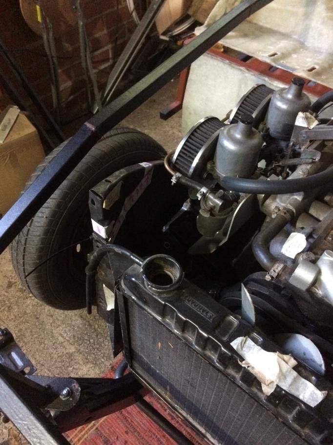
I am planning to use original engine side panels to mount the radiator. I've temporarily placed old radiator to the panels using cable ties to check how it all fits. The top of the panels will stick out, so I have marked the area that could be trimmed to fit under the bonnet.
I hope that the radiator is positioned high enough, using mounting points (holes for the bolts) below the top ones that will be removed (I think these are original mounting points). It will sit a bit higher when it's connected to the top hose, but it seems that the fan sticks out a bit, just above the top of the radiator. Hope that this is ok…any advice is welcome.
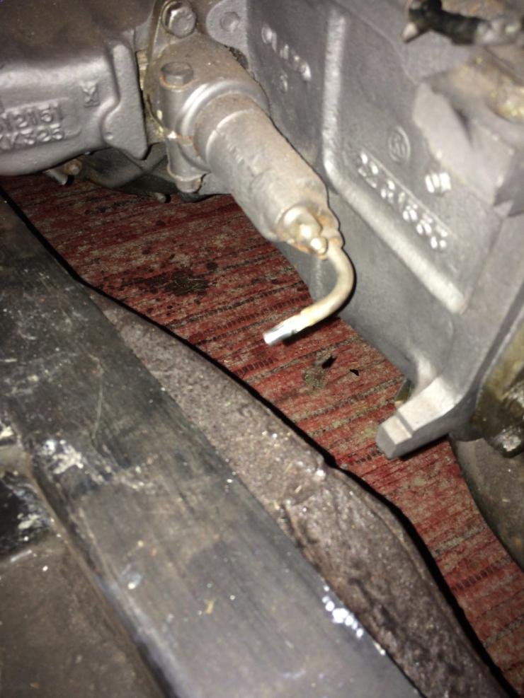
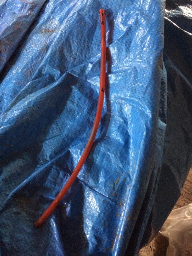
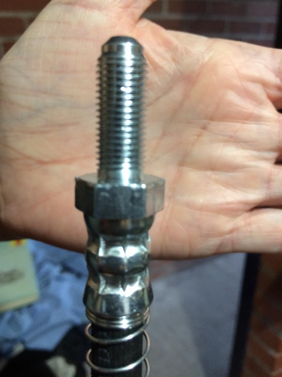
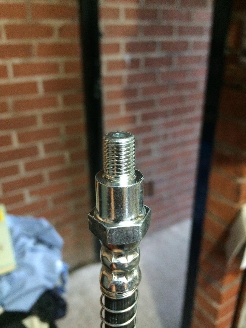
Another thing I'd like to check - my clutch slave cylinder is fitted with a plastic pipe instead of copper one, so the connector attached to the slave cylinder does not have a nut/bolt thread.
I am planning to use a new flexible hose in between master and slave cylinder copper pipes using a rubber break hose.
Am I right in thinking that I can remove (unscrew) the plastic pipe connector from the slave cylinder and screw a new (short) flared copper pipe with the fitting directly into the slave cylinder?
You can either just use a new Midget one or replace the whole thing, connectors and all, with a copper/kunifer one for a Spitfire/Herald, and both solutions are likely to be more reliable than trying to adapt a brake hose.
Paul L - Yes bud I am still chipping away , thanks for your comment. I am not always able to work on the car, but I will finish it!
Mister Towed - Thank you very much for your advice. I was looking to buy a Spit/Herald copper pipe set, but I did not find any containing a flexi hose (which I believe have to be implemented due to gearbox vibrations), so I thought I can use a brake flexi hose in between the copper pipes.
Hi Deni if you need a flexi hose lookup pirtek uk they will tell you the local depot to you they will make you one up just take fitting sizes up or the old fitting and give the length of the hose keep up the good work






 yes Paul, it looks I am in the 'fearless' stage as I am getting more confident in my abilities. I just have to make sure that I don't progress too far, i.e. the 'reckless' stage
  eace:
eace: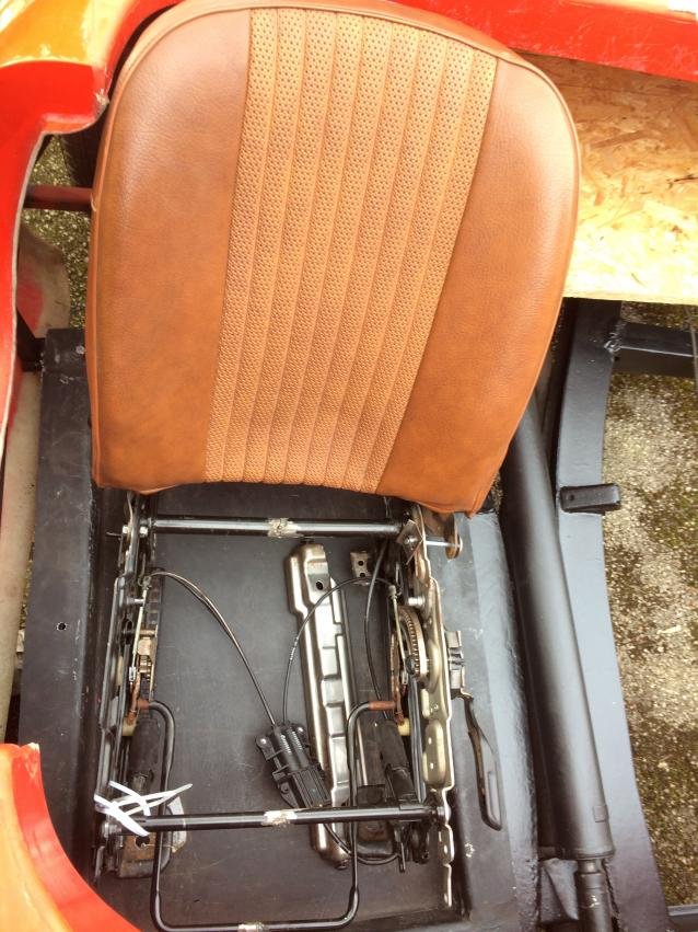

 ) what to do next and how, which also need to happen I suppose....I have made a mock up of the compartment behind the seats. I will make a wood template and make a fiberglass copy of it. Still need to finish the mock up, as I keep changing it to maximise the space. I would like to fit a spare tyre in it and a small bag of tools/things, jack etc.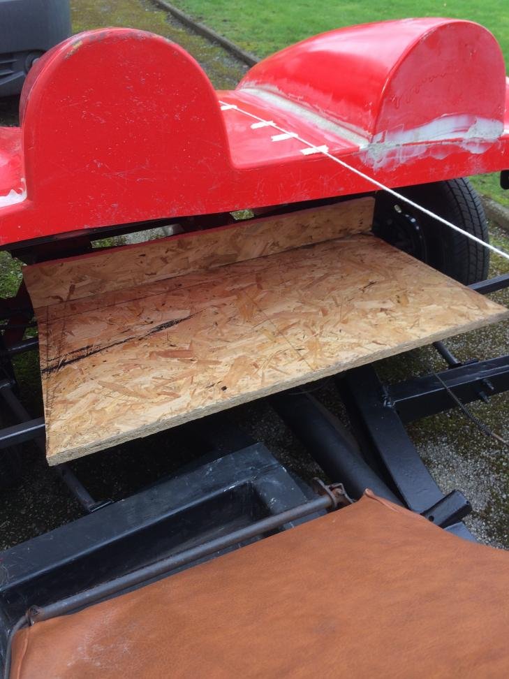

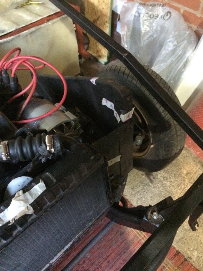
 (I think these are original mounting points). It will sit a bit higher when it's connected to the top hose, but it seems that the fan sticks out a bit, just above the top of the radiator. Hope that this is ok…any advice is welcome.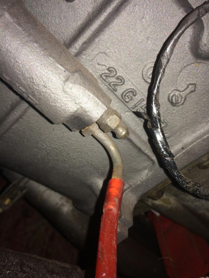
 , thanks for your comment. I am not always able to work on the car, but I will finish it!