MadaboutKitcars

This is a read-only archive of the old Madabout Kitcars forum. New posts and replies are no longer possible, but every thread is still here to browse and read.

Swifty's Navigator

25 Aug 2014, 7:46am
Swifty - Looks like you are making great progress on the body shell. :cool:

I saw you post this on Mac's thread...

swifty wrote:
… once you start to look closely at the misalignment of the body it becomes an obsession a little tweak here and a little tweak there...


At this point I think I am trying to avoid looking too closely at my body shell. :icon_wink:

Good luck, Paul. :)
27 Aug 2014, 8:21pm
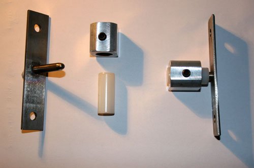
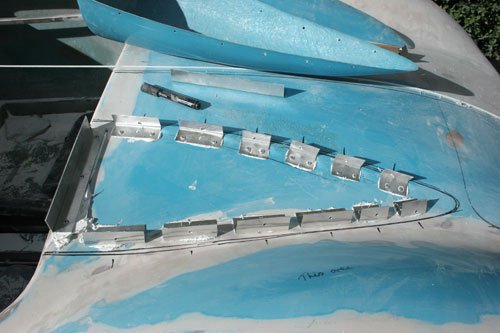
Its been a while since i did any machine work for the car so today i decided to think ahead and make a couple of bonnet locate pegs, these i hope to bond into the fiberglass body and bonnet once i have made a few adjustments to the standard bonnet.

IMG_4638.jpg
IMG_4639.jpg


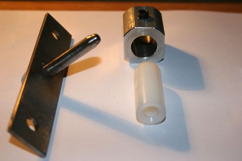
Made the peg and base plate from stainless steel, the peg has a 20 degree taper and is welded to the base plate. I made the female part from nylon to eliminate any future rattles, the hole also has a taper to help guide the pin into the hole.

The grub screw is to allow initial adjustment to set the pin and bonnet up as the hole in the female part is a blind hole, this will then be bonded in permanently. The nylon holder is made from ally with flats machined on to help give a more permanent fixing in the fiberglass.

IMG_4637.jpg


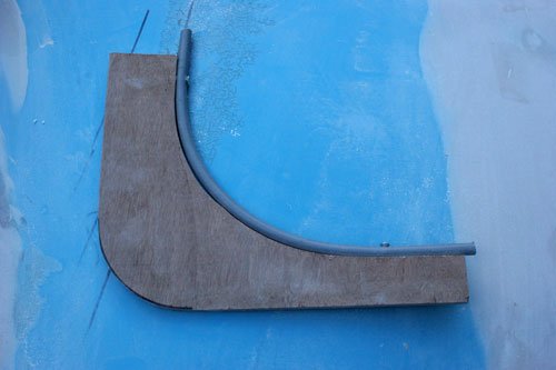
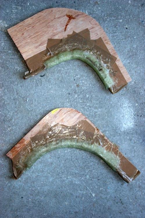
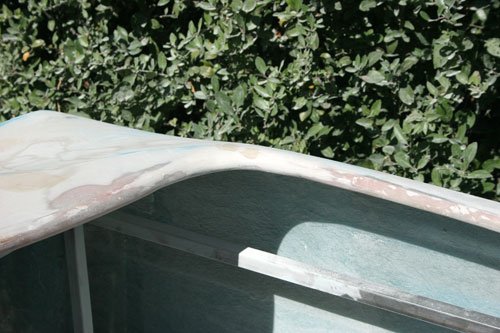
Also made a former for the cockpit corner curved edge's to match the straight edging made earlier, it's made from 1/4 ply with a piece of plastic central heating pipe screw on to give a rounded edge.
This will be covered in brown packaging tape before fiber glassing.

Well that's it for now see you all soon.
28 Aug 2014, 8:28pm
Today i started to fill the cockpit rolled edge trim with fibre filler to blend in with the body so whilst i was waiting for it to set i decide to trim the top of the bulkhead on the nearside as it was not symmetrical with the offside which has bugged me from the beginning.

Attachment “IMG_4642.jpg” from the original forum could not be reliably recovered.
IMG_4644.jpg


Made a cardboard template of the offside top edge profile then transferred over to the nearside. removed the bulk of glass with a flap wheel and tomorrow i will glass the underside before applying the magic glass filler.

So if the weather holds tomorrow i should get the bulk head re glassed and the rolled cockpit edge finished.
29 Aug 2014, 6:59am
swifty wrote:
... I started to fill the cockpit rolled edge trim with fibre filler to blend in with the body ...


Swifty - If you get the chance, could you take a close up photo of this work?

As I am still debating what to do along the edge of my scuttle and this might be a solution.

Although it is clearly hard work at the moment, it looks like you will have a great body shell when you are finished. :cool:

Good luck, Paul. :)
29 Aug 2014, 8:18pm
Paul I will take some photos tomorrow as i forgot to take some today, i have however just about finished the rolled edge now which looks good, it also adds a little strength the cockpit edge which is a benefit.

It does take time but i think the end result looks good and i have a few ideas for the interior to try and replicate a 50's style race car but not sure as to how to tackle this, more thought required or may be just start to do it and make adjustments as i go along.
31 Aug 2014, 12:26pm
Paul I hope these picture give you some idea.

IMG_4640.jpg
IMG_4641.jpg


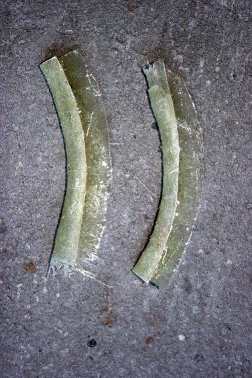
The first image is the corner pieces in the make shift mold and the second is after trimming the corner piece, the deeper edge is what i bonded to the body.

IMG_4645.jpg


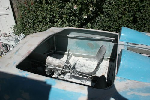
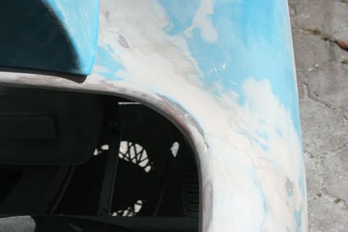
After all four sides and corners were bonded to the body i used fibre filler then rough sand with 180grit wheel to get the basic blend to the body and finally filler.
I also back filled all the way around the inside of the rolled edge to give it more strength.

IMG_4646.jpg
IMG_4647.jpg


A close up of the corner section.

Any questions just ask.
31 Aug 2014, 6:02pm
Swifty - Thanks for supplying all the detail info. :cool:

It does look good, so I will have a serious think about what I do with my own cockpit.

Cheers, Paul. :)
31 Aug 2014, 8:20pm
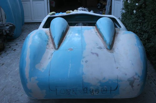
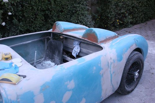
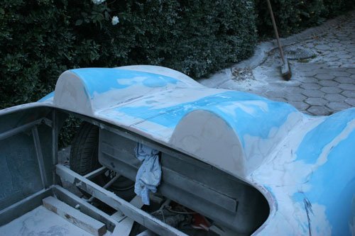
A little more progress made this weekend. Finished the top of the dashboard profile with filler and its now looks to be more symmetrical.

Also bonded the two humps to the body.

IMG_4648.jpg


I used 1mm ally plate to make the angle sections, the same way as mac did. Pop riveted the plate to the body with a little bit of sticky stuff to help, then bent each angle in to match the hump internal profile.

IMG_4650.jpg


The two humps pop riveted in place with some fiber filler smeared on each angle section to add extra bonding strength.

IMG_4651.jpg
IMG_4653.jpg


Used a 120 grit pad to rough the hump surface then smeared fiber filler along the join to blend the pop rivets in, once dry i gave it a rough sanding before adding more fiber filler this time curved to blend into the body, just need to sand to shape and finish off with the easy sand filler.

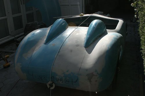
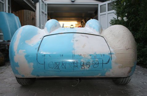
My daughter decide to add a number plate as i was thinking about a boot lid and the rear light position.


Well that's it for today see you all soon.
1 Sep 2014, 6:39am
Swifty - Very neat job on the twin humps. :cool:

I look forward to seeing how you do your boot lid, as that is also on my "To Do" list.

Good luck, Paul. :)
2 Sep 2014, 8:00pm
Paul Thanks and i look forward to seeing how you go about the cockpit rolled edge.

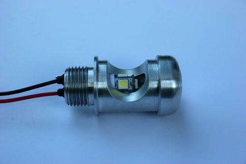
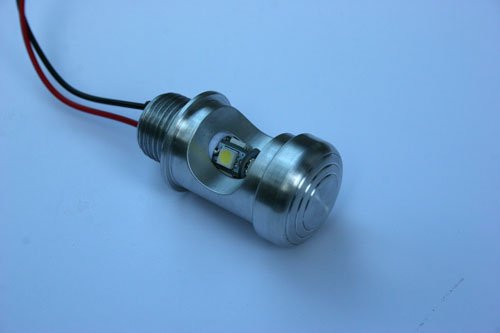
I decide to make a dashboard mounted map light out of ally with a 21st century addition.

IMG_4654.jpg


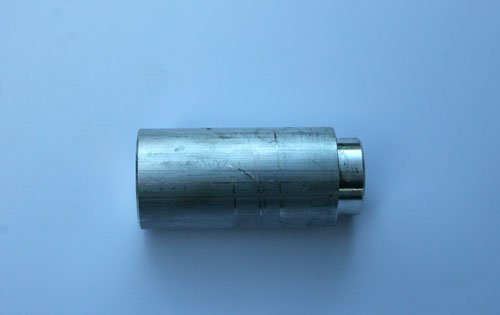
Started with a piece of round bar.

IMG_4660.jpg


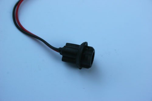
Used a rubber led bulb holder which i trimmed to fit the ally body, bought it from ebay all the way from china delivered for 99p and that was for two.

IMG_4658.jpg


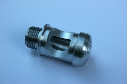
The finished part which was bored out to suit the rubber bulb holder, then a threaded section in 1/2 bsp so that i can use a ready made nut from a pipe fitting and finally machined a semi circle cut out in the side of the body. This was all done on a manual lathe apart from the semi circle cut out which was machined on a vertical miller.

IMG_4655.jpg
IMG_4656.jpg


Finally two photos of the finished item with the led bulb fitted which looks very neat. I may make something similar for the rear number plate light if i can come up with a clear cover to keep the weather out.

Well that's it for now see you all soon.
6 Sep 2014, 7:46pm
Finished the two humps off today with body filler so another job off the list.

IMG_4668.jpg


Also played around with rear light layout and number plate position.

Attachment “IMG_4662.jpg” from the original forum could not be reliably recovered.
6 Sep 2014, 8:01pm
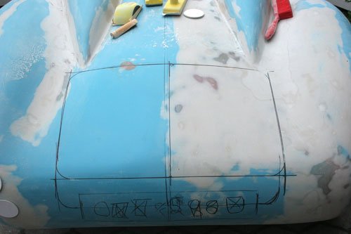
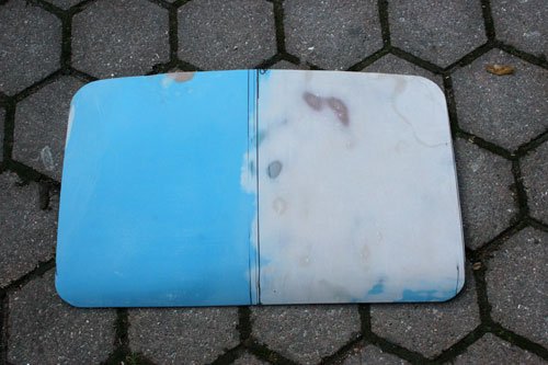
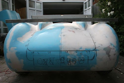
After finishing the humps the next job was the rear boot lid aperture position and size, i need to be able to fit a full size spare wheel into the boot along with a few tools.

IMG_4663.jpg


Marked out with a thick marker and taking measurements from various points to be sure it was central and square, then cut out what will be the lid with a slitting disc and jigsaw.

Attachment “IMG_4664.jpg” from the original forum could not be reliably recovered.
IMG_4665.jpg


Hole cut out with the lid.

IMG_4666.jpg
IMG_4669.jpg


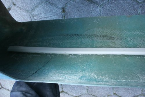
I thought it may be wise to strengthen the lower valance area so used a hot melt glue gun to fasten a length of oval conduit then glassed over for strength. I am thinking about adding a little strength to the lid but will wait and see how and where i attach the hinges, most likely will make ally plate fixings that will be bonded and glassed to the back of the lid.


Well that's it for now and tomorrow i hopefully will have the rain gutter in place once i decide on what to use as a mold, see you all soon.
6 Sep 2014, 8:34pm
Swifty – Your body shell is really coming on in leaps & bounds. :cool:

I look forward to seeing how you do the rain channel.

As I wasn’t sure if that needed to be built before the lid was cut out.

Hopefully my boot access will be in a similar place, but that will cross my two humps.

( The smaller MkII humps certainly make more sense when it comes to a boot. )

Good luck, Paul. :)

PS
Forgot to say your map light is another work of art. :hail:
7 Sep 2014, 8:37pm
Paul Thanks

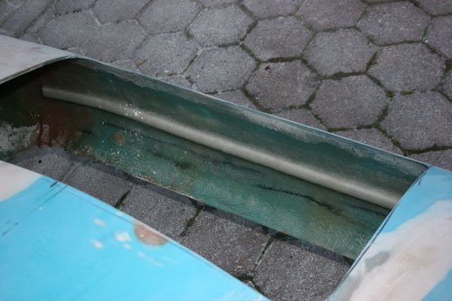
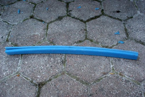
Today i started to mold the boot lid rain channel, after looking around to see what i had at hand to use as a mold i decide on some packaging that came with the steel plate ordered earlier which was used to run around the plate edge.

IMG_4677.jpg


Made from polystyrene type foam its easy to bend and stick down and just so happens to be a good size.

IMG_4672.jpg
Attachment “IMG_4673.jpg” from the original forum could not be reliably recovered.


Used a hot melt glue gun to stick the foam to the inside of the body, first marked a line around the boot aperture to use as a guide, cut a couple of nicks at each corner to help form a bend. Once the foam was glued in place brown parcel tape was applied to the foam to act as a release agent as you will see the area left to remove the foam once the fiberglass has gone off is narrow so the easier it is to remove the better.

IMG_4674.jpg


Applied several layers of fiberglass working from the inside of the upturned body and using plywood covered in brown parcel tape to help keep a straight line and prevent gravity from pulling the glass out of shape. It basically made a u shape with a flat surface attaching it to the body if that makes sense.

Attachment “IMG_4680.jpg” from the original forum could not be reliably recovered.


A close up shot of one of the corner sections with the foam removed, had to gentle pick away at the foam with a Stanley blade and metal ruler, its also easier if you trim the height of the glass edge to give more access to the foam.
Will trim the glass edge further once the rubber seal arrives, i am using the edge seal from car builder solutions code #TRME, will also add a couple of piped drain holes as a good measure.

Well that's it for now see you all soon.
8 Sep 2014, 8:18pm
Another really helpful demonstration / explanation, thanks. :cool:
12 Sep 2014, 8:48pm
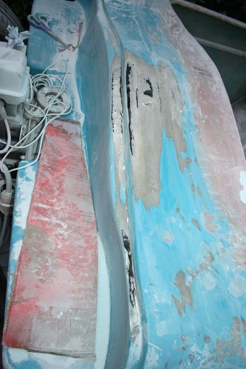
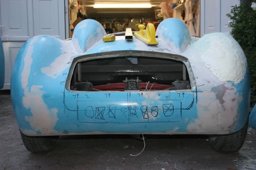
Decided to do more work to the body, the offside rear wing is about 30mm lower and overall shorter in length than the nearside so i decided to make a few cardboard templates of the nearside to copy over to the offside.

IMG_4686.jpg


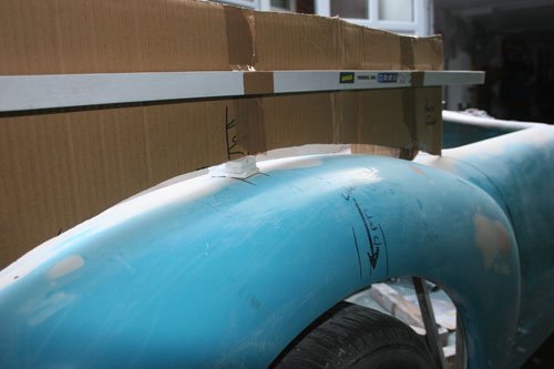
Used a spirit level to find out how low the offside arch is, also made sure that the cockpit was lying level before working out was was to do. The packing is about 30mm which brought the two wing tops level.

IMG_4685.jpg
IMG_4684.jpg


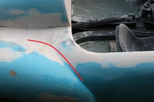
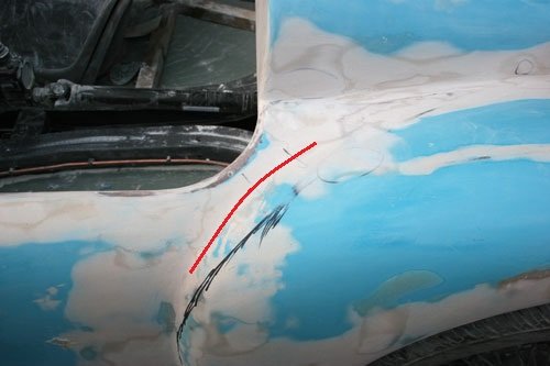
The first image is of the offside i have drawn a red line to illustrate where the wing curve meets the body as the image does not show it too well, the second image is the nearside, you can see the difference in body shape due to the offside wing being shorter in overall length. The position of the cockpit curve is correct in line with the sub frame and chassis center line so i know this is correct.

IMG_4692.jpg


One of the card board templates which shows roughly how much filler has to be applied so i had to come up with an idea that would allow me to roughly get the shape i require without using loads of fiber glass and filler.

IMG_4693.jpg


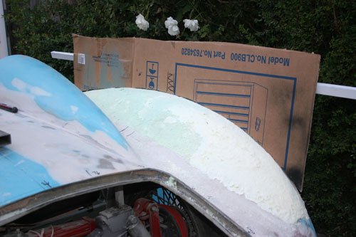
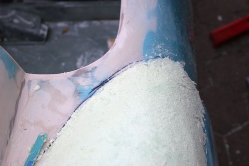
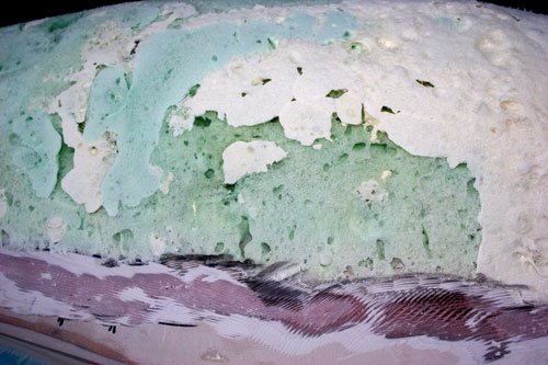
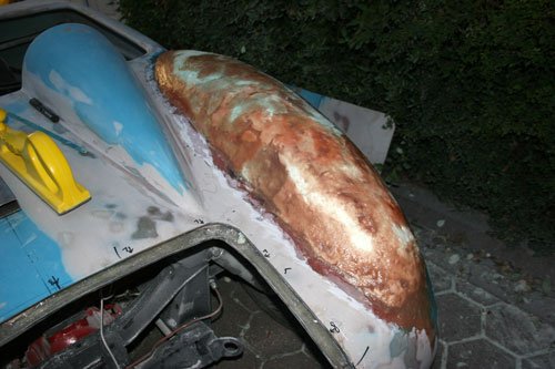
Not sure if this will work as i have not seen it done before. I used a can of foam filler over the surface of the wing which needs to be built up, first rough the surface then wiped with acetone to remove any mold wax. My next plan is to roughly shape the curve by hand then cover with 300g fiber glass matting before covering with fiber filler then hopefully finishing off with body filler.
Has anybody tried this, does it work or will there possibly be problems in the future.

Well that's it for now and hopefully tomorrow i will have the glass mat in place.

See you all soon.
13 Sep 2014, 6:19am
Swifty - Sorry I was half asleep when I posted last night, as I forgot I've used expanding foam myself. :rolleyes:

Admittedly I just covered it with some fibreglass filler, as I hadn't started working with "real" fibreglass at this point.

But I used it to fill & seal the void left where I had cut the windscreen off the Spitfire bulkhead.


Again, this is on a much smaller scale that the work you are doing.

Good luck, Paul. :)
13 Sep 2014, 9:01am
Paul Thanks for the link and images, they instill a little more confidence in what i am doing with the expanding foam, i wasn't too sure how the foam would react with the fiber glass resin.

Well off outside now to start and shape the wing so hopefully more progress by the end of the day.
13 Sep 2014, 7:48pm
Today i started to shape the drivers rear wing in line with the passenger side after leaving the expanding foam on the car over night to make sure it had cured.

IMG_4696.jpg


Made a template of the passenger side rear arch profile and transferred over to the drivers side to use as a guide, used a 18 teeth hacksaw blade loose in my hand and bowing it to get the rough shape then finished off with a ridged surf board with 40 grit paper, its the yellow one in the image below. The image above shows a good profile with the template in place after sanding etc.

IMG_4698.jpg
IMG_4699.jpg


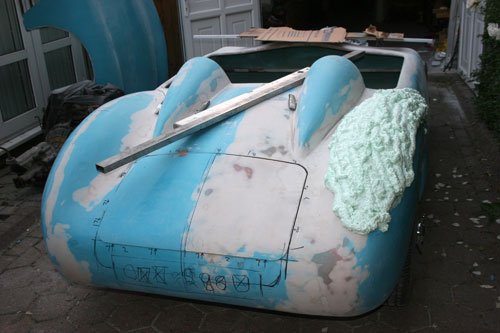
The first image shows the height of the rear arches are now in line with each other and also the distance from the cockpit edge to the rear arch curve is the same as the passenger side, if you compare to the previous thread where there's an image of the passenger side, they are now much the same.

IMG_4701.jpg
IMG_4702.jpg


Ran around the edge with a 140 grit wheel to give a good key for the fiber glass matting and decided to fill the large holes in the foam with fiber filler to get rid of any air pockets in case they caused problems in the future, may be a bit of overkill but its wise to air on the side of caution i think, left the filler to cure overnight before i give a quick sand and then cover in 300g fiber glass matting.

Also started to add strengthening to the sub frame at various points before i chop some of the 20mm box section out to give room for 20mm round tube that i want to use for a more 50's racing look.

Well that's it for now see you all soon.
14 Sep 2014, 4:21pm
Looking forward to seeing what you did today...
14 Sep 2014, 6:41pm
Swifty - Looks like your body shell will end up at the same high standard as your rolling chassis. :cool:

Good luck, Paul. :)
14 Sep 2014, 7:17pm
Paul Cheers i hope to have a good finish but will wait and see how it all turns out.

Not much progress made to today i had hoped to have the wing profile finished but family commitments said other wise.

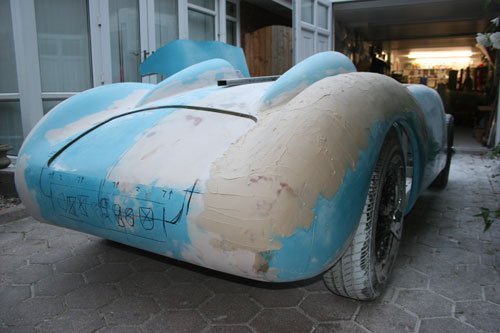
First i covered the foamed area in three layers of fiber glass then used fiber filler to create the shape.

IMG_4704.jpg


Then finished off with easy sand body filler which i hopefully have sanded this next week.

Attachment could not be found in the archived database.
IMG_4703.jpg


I think that you can now see the difference from the before and after images above, the height of the arches are more in line with each other and once the filler has been sanded back it will look symmetrical.

well that's it for now see you all soon.