This is a read-only archive of the old Madabout Kitcars forum. New posts and replies are no longer possible, but every thread is still here to browse and read.
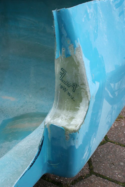
...Is the flat edged of the fiberglass that runs along the bottom supposed to fasten to the steel section of the sub frame, or is this flat edge removed and fiberglass wrapped around the steel section onto the body lower surface...
Swifty – The moulding lip was already removed when my body shell was delivered.
So in my case, the bottom of the shell tucks under the bottom of my framework.
Well it did after I’d butchered the scuttle.
My plan is to fibreglass the frame / floor to the inside of the body shell.
This is how Mister Towed did this on his car.
However, Mac kept a bit of the moulding lip, but added a plate to “lower” the sides of the frame.
…rivet and glue some 3mm plate to the sides of the frame to give me the extra surface area to joint the body to the frame using rivets and PU adhesive…
…The Ali drop plates I fitted to the frame earlier worked nicely and allowed the bottom of the body to actually drop slightly below the frame and also gave a good surface to bond and rivet to. Plenty of the gooey stuff later and voila!...
Hope that helps, Paul.
PS Mac is right about old resin, as I am still using stuff that is almost 2 years old.
However, I do find the “refresher” resin is easier for me to work with.
Paul and Viatron Thanks for the info, i think a little bit more thought on the positioning of the sill is required and TBH i need the larger wheels fitted before any major work is started.
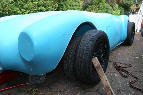
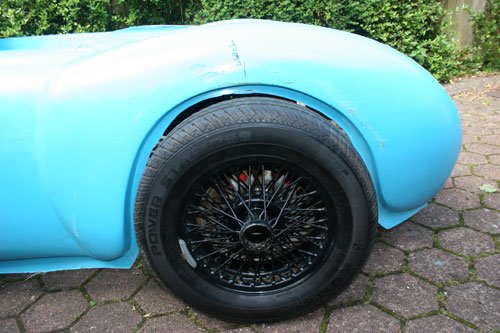
I did how ever stand the spoke wheels against the car and it looks like they are going to fill the wheel arches so there may be clearance issues but wont know this until the hub adapters arrive in the next few days hopefully. Also the hub center is slightly higher for the larger wheels compared to the smaller fitted wheels so that will lift the body up giving a bit more clearance.
The blue and black combo does look good although its not the colour i had in mind at the moment.
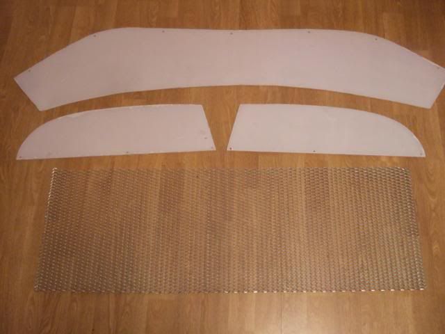
I am looking around for a sheet of polycarbonate to make the screen and thought that 4mm thickness will be ok, does anybody have other thoughts on this?
Also am i correct that the drivers eye line has to be above the screen top edge?
Paul I'm looking to do something slightly different to the standard screen but thanks for the offer.
I suppose that when you take the car for its MOT you may need a booster cushion in case the MOT guy is a little on the short side, or may be a whoopy cushion.
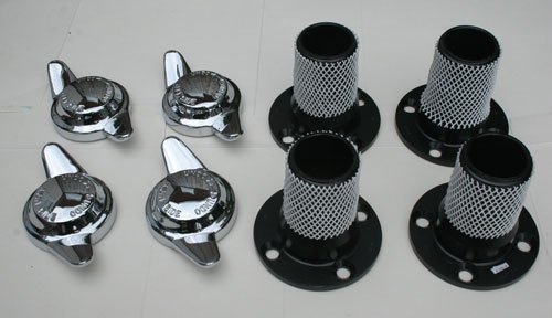
Hub adapters and spinners for 14 inch mgb wire wheels, one slight problem the nuts i order have not been included so after a telephone call they are now on the way with a free upgrade to stainless nuts, hopefully they will arrive tomorrow so that i can start on the body chopping if not i can always butcher the original nuts as a temp fix.
First bit of Fiberglas to the bulk head completed. The clutch slave cylinder on the straight six was fouling the body slightly when i was trying to centralize the body to the chassis.
Hopefully the weather will be kind tomorrow so that i can work outside to cut the body into shape.
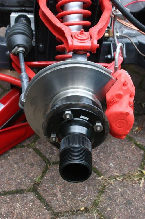
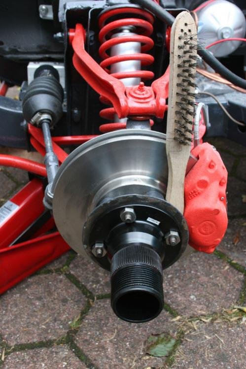
Fitted the hub adapters today which was a very straight forward job.
A couple of picture for those that are not sure what the hub adapters are, the black item bolted to the hub is the adapter, the nuts and splines were greased with copper slip along with the taper seat on the back of the wheel center hub. To tighten the nuts i had to use a wooden handle (pic 2) to stop the hub from turning as the brakes are not connected at the moment.
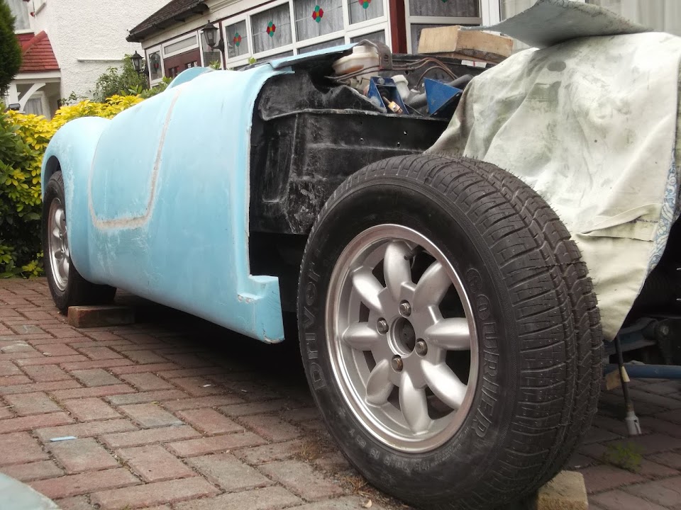
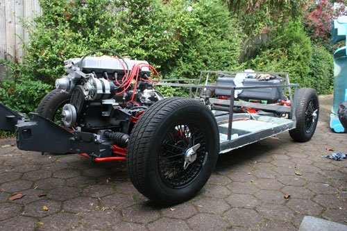
All four spoke wheels fitted, the ride height has been increased by 30mm form the original spitfire wheels.
Welded the floor from underneath to the sub frame as one piece per side, i will probably put a second internal floor in ally to give a neater finish, sealed all edges with polyurethane as a good measure.
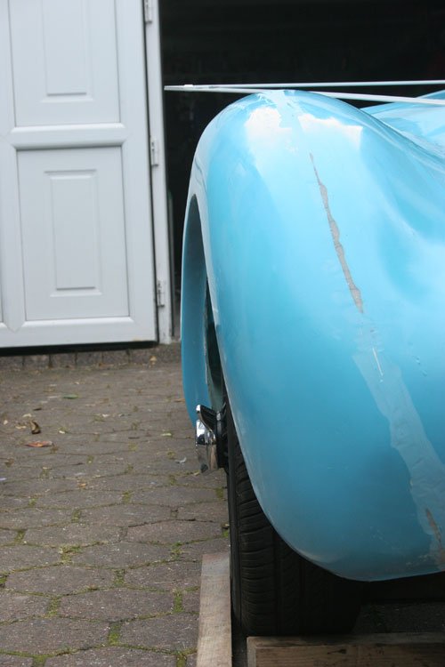
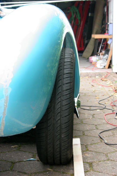
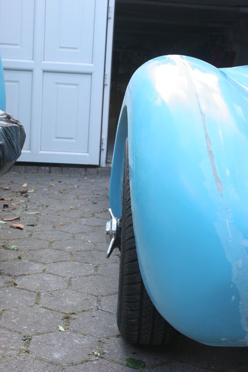
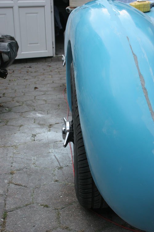
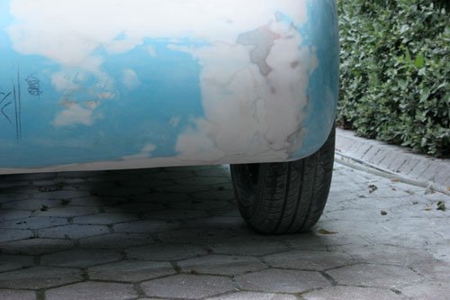
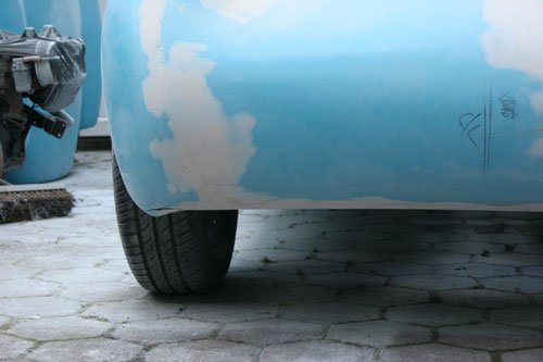
Now that the spoke wheels are fitted i decide to start to try and ballance the body. I decided to start with the offside rear wing, the pictures tell the full story as to how far the body is out.
Attachment “IMG_4602.jpg” from the original forum could not be reliably recovered.
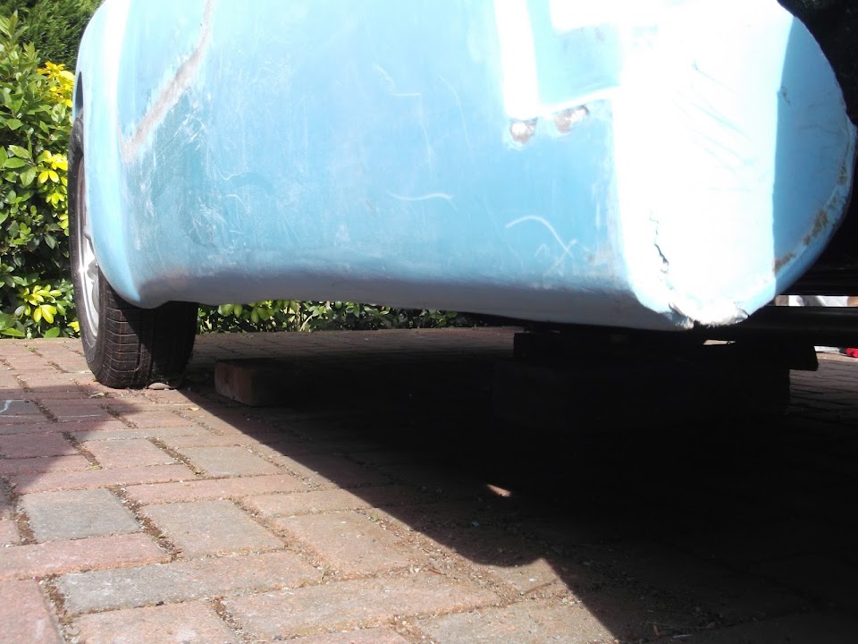
You can also see the rear valance dips on the nearside which will require some work.
I took various measurements across the back of the body and finally came to the conclusion of how much and where to make the cut.
Another area i think will require work is the nearside rear arch, the first image shows the leading edge standing slightly prouder than the offside so i may have to cut this area to move the arch in slightly.
These images show the amount i have had to move the wing out over, it certainly looks like more than the other guys have moved their body out over but this was the only way i could get the end result that was symmetrical and balanced.
Well that's it for now, hopefully i will have the rear arch filled tomorrow and may be a bit more body work completed.
That looks _so_ much better matey! and, no offence, but i'm _so_ hoping that i don't have to go through all of this with the Miglia! <fingers crossed>
One thing about the hub adapters, make sure you loktite or better still 'punch' the nuts in place as i had my nuts come loose (oooh err missus) while driving as i'd forgotten to do that!
Dave I haven't used thread lock but did cross my mind, when you tightened yours nuts did you lock the wheel up to prevent it from spinning like i did?
Paul Yes the rear end is not the best, but what is strange is the fact that i thought most of the rear end problems had been virtually ironed out, when you compare the gap on Macs and mine his looks a lot narrower and the rear valance area does not slope to the nearside, strange.
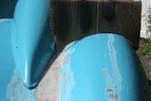
Fiberglas the rear arch and rough filled with fiber filler, it now looks some where near to being symmetrical, will have rub down to smooth out before using a filler. The nearside arch may need a little blending in to match the offside but will wait and see if i can create a more definite line on the offside arch.
Made a profile of the nearside arch to see how much filler was required on the offside.
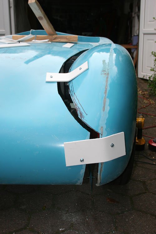
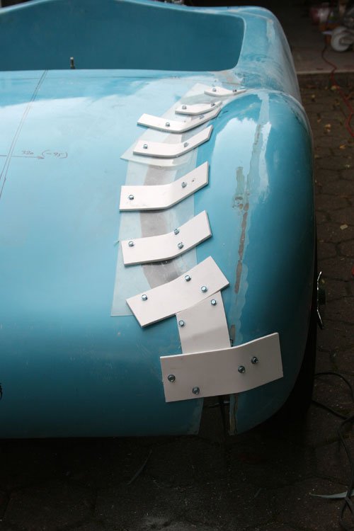
Split the nearside lower rear arch to move it in to match the offside.
A before and after shot which now look more in keeping with the overall body shape. Glassed up and waiting to fill hopefully next week
The more I look at your body mate the more I think it may have warped a bit in the heat! The issue you had with the pass side rear didint exist in mine....
Viatron The body is sitting on the frame until all glass work is completed and the subframe needs more strengthen work.
Its possible the body has warrped, I did try and push the nearside arch in but it ws having none of it so cutting was the solution.
Swifty - Looks like you have made big improvements in a very short space of time.
I think the time/budget restrictions Mac worked under to revise the MkI into the MkII meant it wasn't 100% perfect.
However, given all the issues he had to deal with, the MkII is certainly miles better than the MkI.
Are you going for one hump, or two?
Good luck, Paul.
PS
I can certainly gently push in the leading edges of my arches with no resistance.
( There are photos of them strapped into place in my build thread. )
Dave I haven't used thread lock but did cross my mind, when you tightened yours nuts did you lock the wheel up to prevent it from spinning like i did?
Yup, i did the same as you with a bit of steel bar. But about 3 weeks (i think) after it was on the road it came loose! Squeeky bum time as it did wobble like heck!
I ended up refitting them with loktite and that sorted them for the rest of the year i was driving it, but this time i'm going to do belt-n-braces and 'punch' them as well
Yup, i did the same as you with a bit of steel bar. But about 3 weeks (i think) after it was on the road it came loose! Squeeky bum time as it did wobble like heck!
I ended up refitting them with loktite and that sorted them for the rest of the year i was driving it, but this time i'm going to do belt-n-braces and 'punch' them as well
I thread-locked my hub nuts in (oo-er, missus) from the word go as it was quite difficult to get them really tight due to them being shrouded by the hub flange. A year on and my nuts are still nice and tight up against the flange (fnarr, fnarr).
Took your advice guys about thread locking the adapter nuts just in case.
After looking at the way the rear end of the body dipped down on the offside i decide to to make s few adjustments to bring it in line with the nearside.
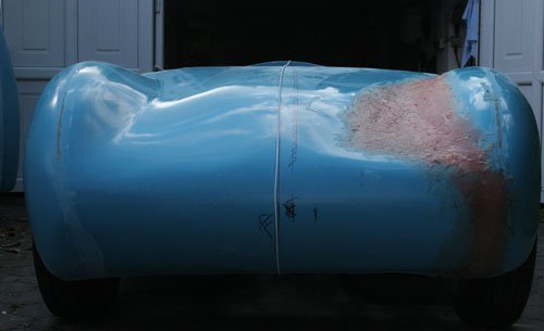
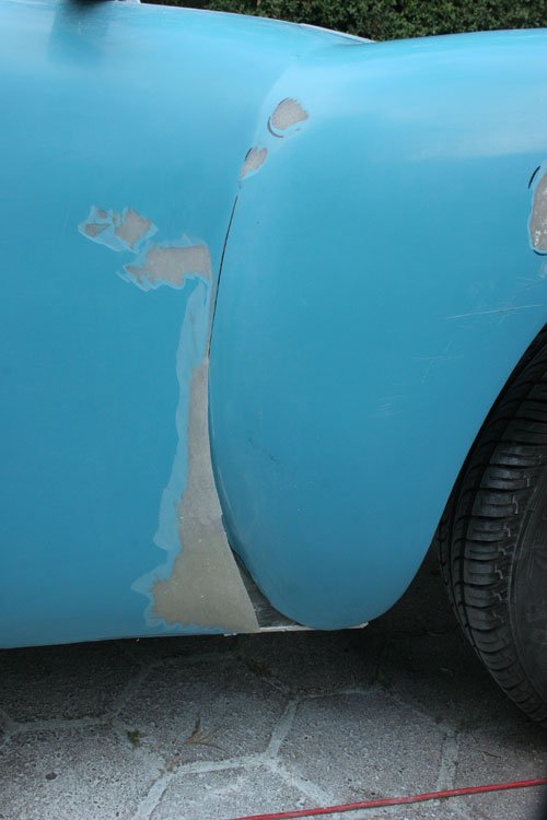
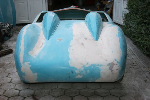
Started by running over with 80 grit flap wheel then built up the surface with fibre filler followed by body filler and it now looks more balanced with the nearside and the two humps sit better on the body.
Attachment could not be found in the archived database.
The first image gives you some idea of the problems with the body alignment and the second is after some major work.
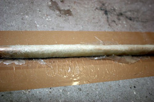
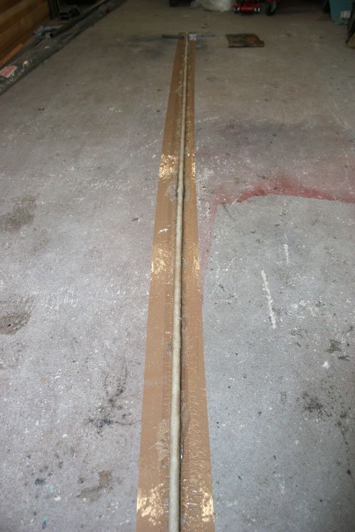
Also opened the width of the cockpit by trimming the sides to give more shoulder room this has left an edge with no strength so decide to add a rolled edge. Made a mold to make a trim to go around the edge of the cockpit out of a 3 mtr length of plastic oval conduit, this was used to wrap the fiberglass around then once cured i ran a slitting disc down one side to leave a rolled edge trim which turned out good.
The curved inbuilt dash has been removed as i am going to fit a flat dash board, this has left a curved section in the middle which needed to be filled in. I used a piece of 1/8th ply covered in brown packaging tape and screwed to the under side on the dash to use as a surface for the fiberglass to rest on.
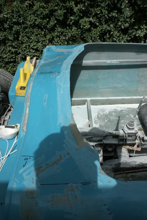
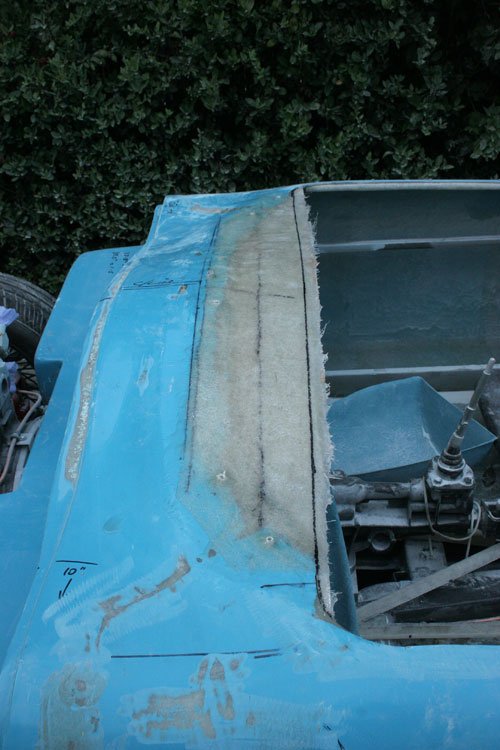
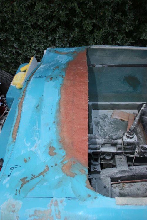
Area glassed in and marked up before cutting the straight edge.
Filled the newly glassed area with fiber filler before the body filler is used.
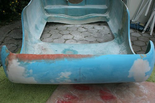
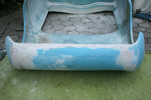
After sorting the area on the offside i decide to tackle the rear valance area which was uneven and sloped to the nearside.
First the edge was trimmed straight and filled with fiber filler as the valance profile was all over the place and i wanted some continuity.
Body filler was then used to finally give a flat smooth finish before the primer goes on.
I fitted the body back onto the chassis only to find that the nearside rear arch was slightly lower than the offside so a cut was made in the rear arch trailing edge, if you look at the image above you can see the difference in the formation of the two rear arches.
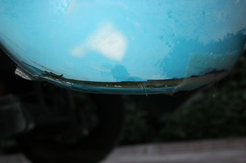
This image shows the cut after fiberglass was applied.
These images show the slight difference before the cut was made to the nearside arch. The first image is the offside while the second image is the nearside you can see the difference which i marked with a marker pen before cutting.
Well that's it for today hopefully will get some more body work done soon plus the sub frame is going to be re made to fit the body better and look more in keeping with the style of car.