MadaboutKitcars

This is a read-only archive of the old Madabout Kitcars forum. New posts and replies are no longer possible, but every thread is still here to browse and read.

Another Cordite Is Born ...

3 Mar 2015, 1:05pm
Struggling To Keep It Simple:
While I was waiting for the morning's rain to dry up, I quickly re-arranged the mock up of the mirror pedestal.

Just a small change to where the two "outside" tubes join the top plate.

Before:
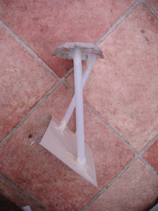


After:
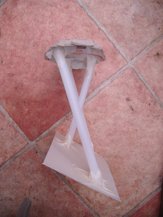


This design is really starting to grow on me, especially if I make it an "optional extra" that can easily be removed.

- - - - - - - - - - - - - - - - - - - - - - - - - - - - - - -

I cleaned off the small ring of bonding paste around one of the rivets on the petrol cap ring.

Then gave it a quick touch up with etch primer.


- - - - - - - - - - - - - - - - - - - - - - - - - - - - - - -

The four external catches I ordered turned up today and this gives you an idea of their size compared to the locking pins.


Although I may make some simple metal plates & rivet them to the body shell to spread the load of the fixings.


Note:
I would paint the plates BRG to match the petrol cap base ring & exhaust shields.

I need to sort out the locating pins before I can think about fitting these.

But that will be something I can only do by crawling under the body shell when I remove it.

- - - - - - - - - - - - - - - - - - - - - - - - - - - - - - -

I sanded down the extra filler I had applied to the rear number plate plinth yesterday.

I plan to finish off the bottom edge when I can turn the body shell upside down.

But for now, I just marked a straight line at the bottom as a rough guide.


I also softened all the edges.


There are still a few ares that I need to "top up" with filler, but that will do for now.

- - - - - - - - - - - - - - - - - - - - - - - - - - - - - - -

Unfortunately, when I looked at how I could the mount the LED number plate lights, the wheels came off a bit.

The problem is that the fixing bolt is simply not long enough. :frusty:


The nut is at the very end of the thread and doesn't cover the depth of the plinth & number plate.

At this point I cursed my lack of experience, then just cursed in general in an attempt to make me feel better. :rant:

My initial thoughts started to think building about how to build a "hollow" mounting point for the LEDs.

This would involve making a hole in the body shell behind the mounting point to reach the LED nut.

After a short period of beard scratching it was clear it would take a huge amount of extra work to fit the "wrong" part.

When I first saw the LED number plate lights I thought they were a great idea.

But the cold reality is they are not a great idea for me. :icon_sad:

So it was back to the drawing board (again) and I had another look at DaveCymru's great set up.


By chance, on the same page of Dave's build thread there was this photo of Mister Towed's & Phil9's cars.
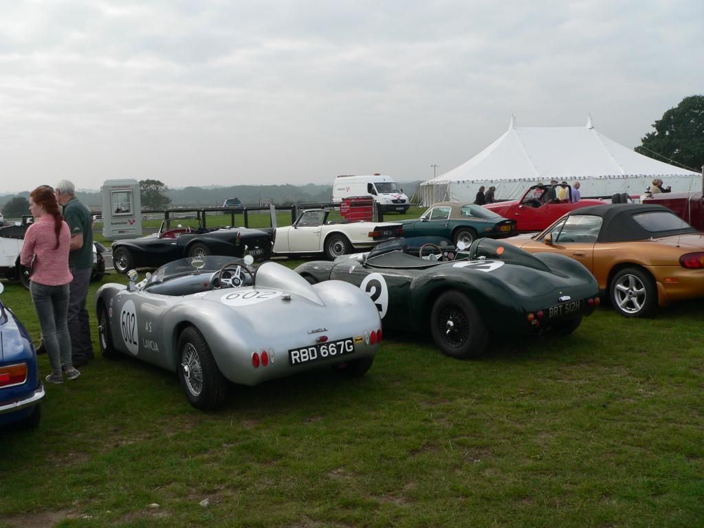


Clearly Phil has the same "traditional" light & after a quick look at a few other photos, so do lots of others.

Which makes me question why on earth I am trying to re-invent the wheel in the first place. :rolleyes:

Given that I have already built a plinth for the number plate, I would need to build one for this style of number plate light too.

Whilst this wouldn't be too hard to do, it did lead me to have a closer look at the way Mr T's light works.


This is actually a great use of something designed for motorcycles.


Which means Mr T can simply bolt his number plate to this and doesn't need any sort of plinth.

So clearly I would be much better off If I simply stole every good idea that Mister Towed has on his car. :icon_wink:

However, I do take a crumb of comfort from the fact that this was not his first design idea either.

But the real key for me is that I am slowly getting better at spotting the start of a wild goose chase.

This means that I have now ordered the same rear number plate light as Mr T. :cool:

When it arrives, I will "simply" grind out a section of the number plate plinth so it can be fitted flush.

I will also need to adjust the rear wiring loom, but overall I am still saving time with this approach.

So I don't mind the fact I need to buy something else, as saving time is a bigger priority for me at this stage.

Unfortunately, this is another day when I need to spend more time on non car stuff.

So until next time, take care, Paul. :)
4 Mar 2015, 12:48pm
Possible Boot Lid Breakthrough:
I am in a bit of a holding pattern at the moment waiting for my new tarpaulin to arrive so I can remove the body shell.
( Which will mark the start of the final preparation work on the rolling chassis / moon rover. )

But I got some new bolts and penny washers in the post today, so it was time to go back to this nightmare...


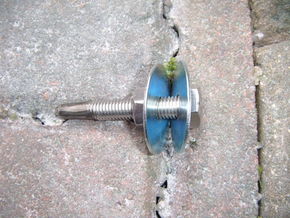
I ground the thread off one end of bolt just to see if my idea for a locating pin would work.


The basic plan is to re-use the four existing bolt mounting plates, but move the holes to use the penny washers.

Top Edge:


Bottom Edge:


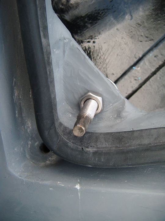
Then the "locating" bolt would fit something like this.


I would then add a new section to the underside of the lid for these bolts to fit into.

However, I need to fix the problem I was having with the locking pins, which is linked to getting all four bolt to line up at the same time.

If I look at the top edge bolts from above, they are petty much pointing straight up.


However, the bolts on the bottom edge would currently end up at an angle off vertical.


Whereas I need them to point straight up to match the top edge ones, something like this.


I think this came about after trying to keep the locking pins perpendicular to the lid, but the lid itself curves from top to bottom.

Unfortunately, while fixing that is straight forward, it leads me to another fundamental design flaw in my boot lid design. :rolleyes:

I fitted the handle in a traditional position towards the bottom edge of the lid, where it look the part.

The issue is that I can't lift the boot lid "straight up" using just the handle. :frusty:

The bottom edge of the lid comes away cleanly as you would expect.


But the top edge want to stay where it is and so the bottom edge "levers" against it.


Because of the way the lid cuts through the hump and the fact the panel "gaps" are small, there is no way to pick the lid up at that end.

Note:
It is easy to lower it into position using two hands and I think this was where I was going wrong in the first place. :icon_sad:

So the good news is I think it is possible to lift and lower the boot lid in such a way that the locating pins will work.
( Once all four base plates have been adjusted to the same horizontal level. )

The bad news is that I need to fit something to the top edge of the boot lid, between the two holes seen above, to help me lift it up cleanly.

So I have ordered one of these stainless steel eyebolts, which I can pull against with my finger.


Even though this means that removing the boot lid will be a two handed job, at least it can be removed!

Clearly this is going to make the whole boot area look a lot more "home made" that I originally intended.

But the simple fact is that whilst creating a "proper" boot area was a good idea, it was definitely beyond my skill level.

So I am pretty happy that I have finally got to the point where I might actually have a working solution.

It might even be worth me having one last go at using the locking pins (at least at the top edge) when the eyebolt is in place.

As if I can cleanly lift the lid "up & down" this may solve some of the problems I was having getting everything to line up.

But for now my head hurts and I am still have a lot of non car chores to catch up on.

So I'd better go, cheers, Paul. :)
4 Mar 2015, 1:20pm
What about two springs under the top mounting points around each pin? Just sufficient to lift the lid high enough to get your fingers in to lift it off. Press the lid down and secure it.
4 Mar 2015, 3:59pm
Or fit some internal hinges to the left /right side so you can open it sideways,2 locking pins on the other side which secure it and 2 dummy pins on the hinge side.
4 Mar 2015, 6:28pm
8 Value Ed & Rene - Thanks for the suggestions gentlemen. :cool:
However, I need to stick to a very simple solution, as I've already spent far too long on this boot lid.
Hopefully others will learn from my mistakes and make a much better job of their boot lids. :rolleyes:

- - - - - - - - - - - - - - - - - - - - - - - - - - - - - - -

Extra Time:
A week later than promised, but my new tarpaulin finally arrived this afternoon.


So when my wife got home I could get her to help me lift the body shell off the framework.

Although by now the sun was going down and my driveway was actually in sunshine for a change, so I took a couple of photos.


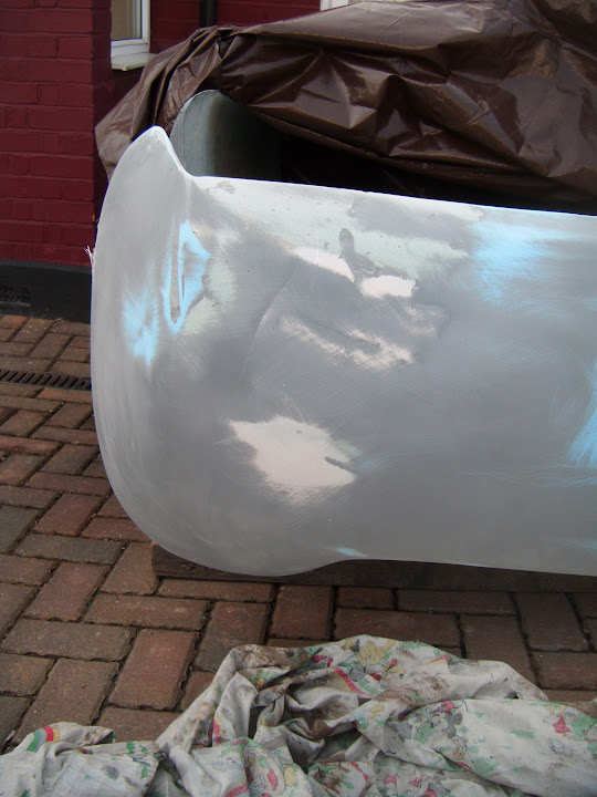
Once the front arches & rear of the bonnet are shorted out, I think this will end up looking pretty good. :pray:

Similarly, the area just in front of the rear arches on the driver's side will be "pulled in" then the body is bonded on.


I've left the bonnet in place for now, as I will initially be working on the rear framework.


I've also left the body shell upside down for now.


As this will give me better access to the bottom edge of the number plate plinth and the tail pipe exits so I can sort out the metal shields.


Plus I need to clean up the underside of the petrol cap base ring.


Once that is done. I will double check the gap around the rubber seal when it is fitted.

But it was too late to start any work this evening, but at least the new (& bigger) tarpaulin completely covered the body shell.


These heavy duty tarpaulins will keep the water out, while the "proper" car covers just act as decoration. :rolleyes:


I know there is still a lot of work to do, but at least I am getting closer to actually starting the final building stage.

Although I must confess I find myself dreaming of a double garage these days. :rolleyes:

Cheers, Paul. :)
4 Mar 2015, 6:59pm
A tent is an easier solution Paul! It works for me very well.

Good luck with the boot!
4 Mar 2015, 7:00pm
Paul,

I had(have)the same problem with my "small inner bonnet",the locking
pins don,t line up.
I placed the type quick release pins with the pins and rings on it,after some filing of the holes it fits very good and I can raise the small bonnet by lifting
it on the rings (two hands),works perfectly!
5 Mar 2015, 5:36pm
Scottie - These days I'm quite jealous of your tent too!

Jerome - Cheers, I went back to have another look at inner bonnet.
Which also reminded me that I really like your twin exhaust pipe shield design.

- - - - - - - - - - - - - - - - - - - - - - - - - - - - - - -

A Good Start - Part 1:
Finally got a good run at the car today and managed to get quite a few small jobs done.

Although as Scottie often points out, just because they are small, doesn't mean they are not time consuming!

So I will group the jobs together, rather than follow the strict timeline of the day.

Petrol Cap Base Ring:
Cleaned off the excess bonding paste that had been squeezed out along the inside edge.


Note: I will come back and file the straight section you can see on the bottom right at some point.

Quickly fitted the rubber seal and thankfully that sits nicely in place.


So when the petrol cap is fitted, everything works as it should.


- - - - - - - - - - - - - - - - - - - - - - - - - - - - - - -

Rear Valance & Number Plate Plinth:
Sanded off any excess filler from the bottom edges of the plinth (& around the tail pipe exits while I was at it).


Also tidied up the outside edges, where the previous "cut & shut" repair work has been.


Gave these areas a skim of normal body filler.


Which was later sanded down to give a smoother, if still somewhat undulating, surface.


Followed by a quick dusting of etch primer just to get a better feel for progress.


I will have to add a dab of stopper filler "here and there" at some point.

- - - - - - - - - - - - - - - - - - - - - - - - - - - - - - -

Exhaust Tail Pipe Shields:
These needed to be bent into shape.


So my trusty block of wood and a selection of hammers were used to get the shape required.


Which was actually quite a tricky curve to achieve.


Then the inside edges were trimmed to match the two cut outs, which are not identical. :rolleyes:


Notes:
- I will trim the back edges flush with the body shell when these have been fitted.
- I also flatted the shield's curve underneath the number plate plinth to create a bit of a visual gap.

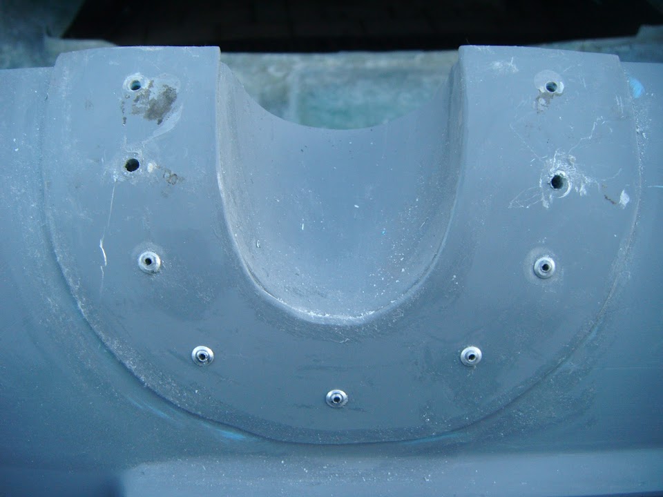
After drilling some holes for the rivets (these will also be bonded on), I cleaned them up.


Before giving the inside edges a coat of etch primer.


Thankfully the weather held and so there was time to do the "outside" too.


- - - - - - - - - - - - - - - - - - - - - - - - - - - - - - -

End of Part 1...
5 Mar 2015, 5:38pm
A Good Start - Part 2:

Internal Framework:
The "between humps" supporting brace was looking a bit sorry for itself.
( The green blobs are plastercine used to act as a guide to adding bonding paste. )


So that was cleaned up.


Then the final round of welding along the edges was completed.


The box section used to join the rear wheel arches to the framework was also a mess.


So that was also cleaned up and the open end was "capped"


Note: Obviously this was done on both sides.

The rough edges of the seat belt mounting brackets were also tidied up & capped.
( These were cut to allow the body shell to sit lower. )


Again, this was done on both sides, before all of the above got a coat of Kurust.


I must confess it feels good to be welding again, as that always makes me feel like I'm making something. :cool:

- - - - - - - - - - - - - - - - - - - - - - - - - - - - - - -

Eye Bolt:
Very impressed when the eye bolt I ordered yesterday arrived today.


It would sit proud of the boot lid something like this.


But actually be positioned roughly where the base of the "eye" is in this photo.


Just for the record I weighed the boot lid & it came in at just over a stone / around 6.6 kg. :eek:

So even if an eye bolt is an unusual feature on a 1950s racing car, it will definitely be a big help.

- - - - - - - - - - - - - - - - - - - - - - - - - - - - - - -

Overall. it was nice to finally have a day where I could really get stuck into the build and have some visual progress. :cool:

So until next time, take care, Paul. :)
6 Mar 2015, 2:58pm
Ying & Yang - Part 1:
After quite a productive day yesterday, I should have know better than to expect two good days in a row...

Internal Framework:
Painted over yesterday's work.


Realised there was not much paint left in the pot, so decided to quickly use it up on a few other areas.

Front corners of the bulkhead.


Plus either side of the hand brake panel, where I'd joined it to the floor pans.


Unfortunately when I leaned in to paint this area, I rested my arm on the freshly painted support panel. :frusty:


Thankfully there was just enough paint to fix the mess I'd made with my arm.

I will be giving the entire framework a final coat of paint before bonding on the body shell.

But just seeing these small areas freshly painted is enough to lift your spirits. :cool:

- - - - - - - - - - - - - - - - - - - - - - - - - - - - - - -

Petrol Cap Base Ring:
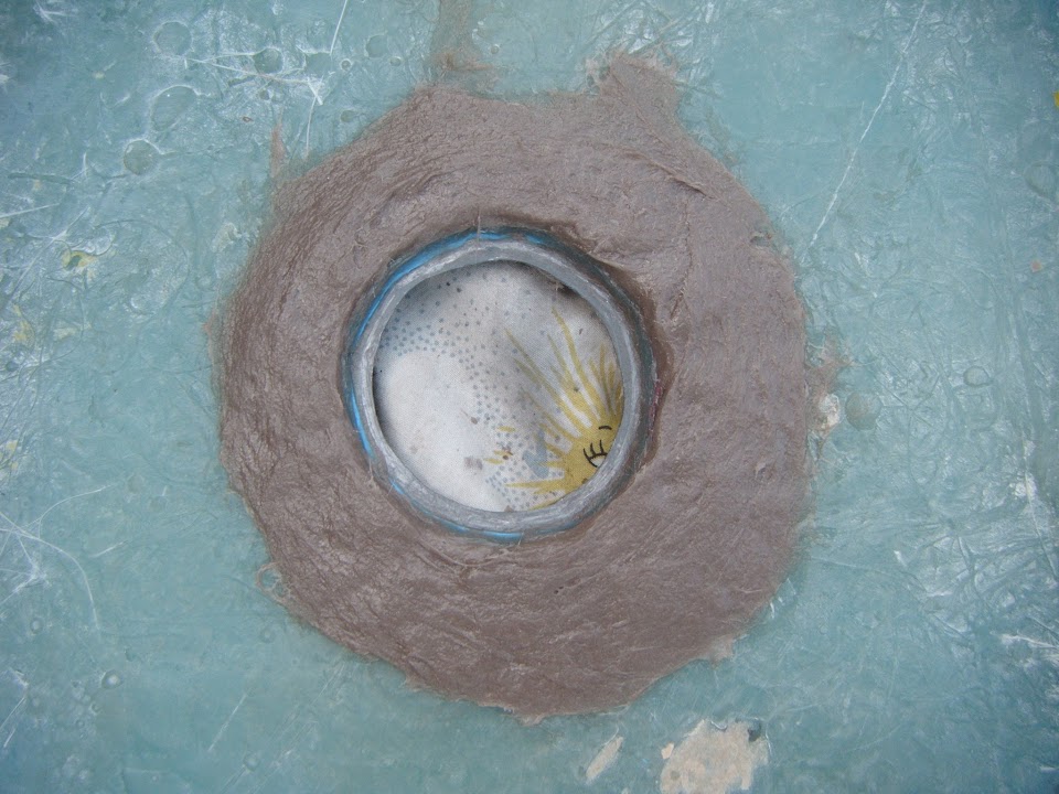
Took a hand file to the inside edge to leave me with a slightly better inner circle shape.

Before:


After:


I still need to cover the rivets with some fibreglass filler to ensure they are sealed.

And I might "nibble" away a little bit of the fibreglass outer circle if I get the chance.

- - - - - - - - - - - - - - - - - - - - - - - - - - - - - - -

Boot Access Panel:
Marked out the best place to fit the eye bolt.


Even though this position lines up with the other handle, it is not in the centre of the two humps.
( Because the two humps are not in the same place relative to the centre line. :rolleyes: )

I also had to take into account the cross bracing underneath.

I've "arrowed" the pilot hole to show where it is.


Made a cardboard template for an oversized spacer to spread the load on the underside.


Which I will need to cut out of metal, bend into shape and bond into position like the one I made for the other handle.

But for now, I just drilled the hole and test fitted the eye bolt.


Hopefully when the lid is painted it might at least look like a functional addition. :pray:

End of Part 1...
6 Mar 2015, 2:58pm
Ying & Yang - Part 2:

Exhaust Tail Pipe Shields:
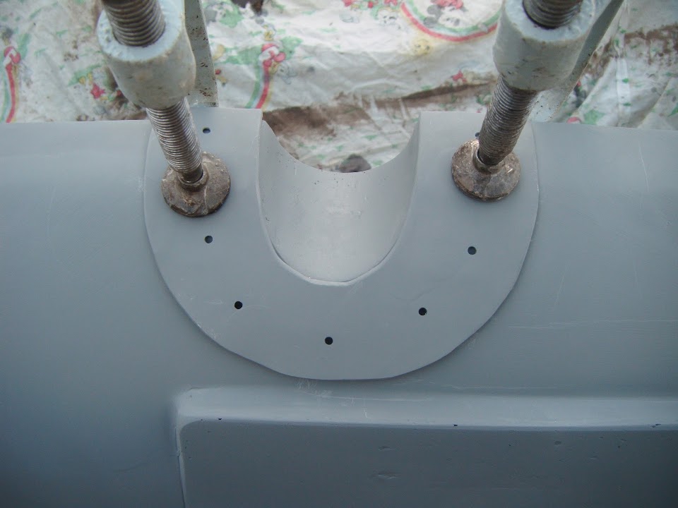
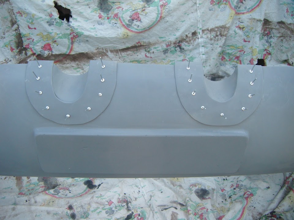
Clamped the shields to the body shell & drilled the corresponding holes into the body shell.


Checked that every rivet would fit in nicely.


Then double checked that they all fitted nicely through the metal.

After a few minor tweaks, the shields were ready.


Came up with a great way to measure the bonding paste, as 50ml fits neatly into this yogurt pot corner.


Then I can tip it into the main pot, add the catalyst, stir & apply.

Unfortunately, with two shields to do, I knew it would be a race against time.

Thankfully I decided to rivet both shields at the same time, starting at the bottom (as you look at the photos).

Then I worked my way up from the bottom doing the next two rivets on each side.

This was just as well, because then disaster stuck and my rivet tool broke. :rant:

I tried swapping to a different size head, it half pulled some and then gave up completely.

At which point panic was setting in as I didn't want the bonding paste to set without the shield "pulled in" tight.

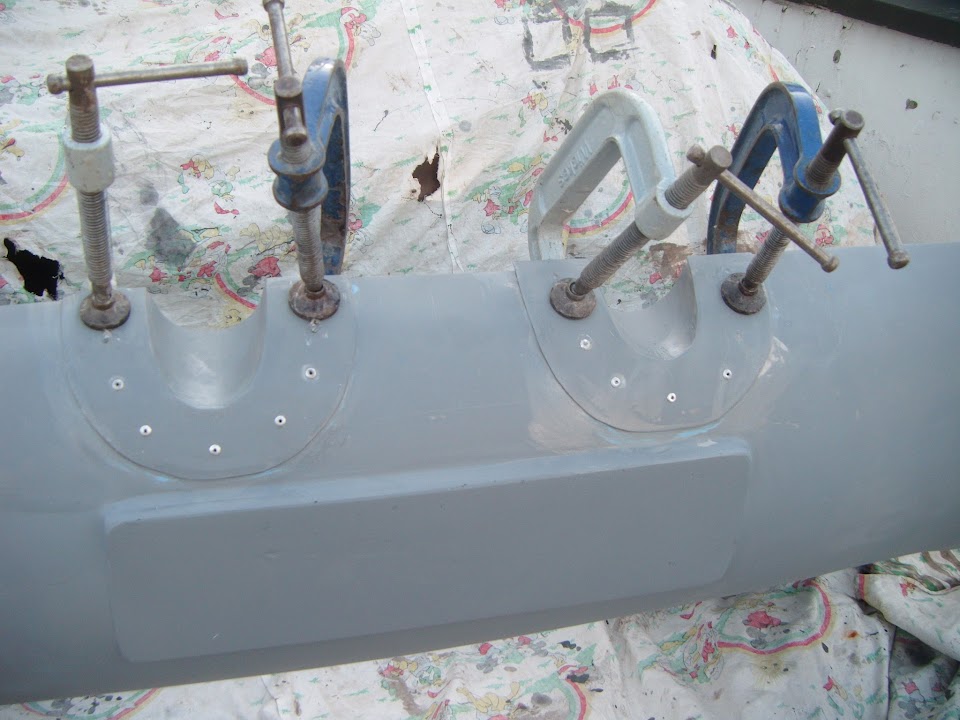
Luckily I remained calm enough to find my clamps and use them at the top edges of the shields.

The clamps squeezed the bonding paste out in the same way that the rivets did, so all was well.


At some point I will have to carefully drill out the broken rivets and fit some new ones.

Wiped off the excess bonding paste.


Notes:
- I still need to trim the back edges to match the body shell.
- I also need to tidy up the inside edges a bit more to make a smoother surface.

But for now, I've just covered this all up for the night with the clamps in place until everything is fully set.

- - - - - - - - - - - - - - - - - - - - - - - - - - - - - - -

Number Plate Light:
This arrived in the post today.


I will not hit any of the number/letters on the plate if I fix bolts through the slots provided.


Although I need to have a bit of a think about where the back of the light will go.


As this is much deeper than the plinth itself (this is the top edge as the body shell is upside down).


So for now, I have put this to one side, while I carry on with other areas of the build.

- - - - - - - - - - - - - - - - - - - - - - - - - - - - - - -

Given all the other things I'm supposed to be doing today & tomorrow, it might be Sunday before I do anything else.

So until then, take care, Paul. :)
6 Mar 2015, 3:57pm
just to be different fit the light at the bottom of the numberplate with the no.plate light shining up?
7 Mar 2015, 6:24pm
RedRatBike - Unfortunately the "upside down" position would be too close to the twin tail pipes. :icon_sad:

- - - - - - - - - - - - - - - - - - - - - - - - - - - - - - -

Bonus Inch:
I was out of the house all day, but there was just enough time to grab a few minutes on the car when I got back.

I removed the clamps from the exhaust shields and everything is bonding in place nicely. :cool:


Then I drilled out the broken rivets and re-opened the rivet holes that were filled with bonding paste.


I've ordered a new rivet tool and that should be here next week, so I can add the missing rivets then.

At which point I will trim the back edges in line with the body shell.

By now the sun was setting...


Even though I'd spent most of the day in a T-Shirt, the temperature really plummeted at this point. :eek:

As it was, I only had enough time to start sanding down any remaining traces of the bonding paste anyway.


When I get the chance to finish that job I will give everything another quick dusting of etch primer.

But that is all for today, cheers, Paul. :)
7 Mar 2015, 7:17pm
Paul have you sorted your mirrors yet, as I found these motor bike ones.
There FOC if you can use them, one will need a new glass.


Just to say when I use a "full" rear light as a number plate light I wire the side light in as normal to illuminate the number plate but then I wire the brake light up as the fog light. :smile:

As long as it's in the middle and the correct height it will pass a MOT test. :smile:
8 Mar 2015, 4:26pm
Micky1Mo - Thanks for the kind offer of the mirrors. :cool:

But I will definitely be using the two chrome bullet ones I have.

The only question is whether the passenger side will be simply mounted directly onto the side of the body shell.
( Which is how the driver's side will be fitted. )


Or whether I will mount the passenger side mirror on some sort of raised bracket like this.


My current plan is to make the bracket an "optional" item, so hopefully either way works.

If you see below, there has been yet another change in plan regarding the rear number plate light. :rolleyes:

- - - - - - - - - - - - - - - - - - - - - - - - - - - - - - -

Sunday Service - Part 1:

Exhaust Shields:
Finished sanding off the excess bonding paste from around the exhaust shields.


Also used a hand file to produce a smooth transition from the inside edge of the shield to the body shell.
( As before some bits of metal sat proud of the fibreglass. )


Gave this a quick coat of etch primer.


Once the final rivets are in, I'll trim the rear edges of the shields and this area will be finished. :cool:

- - - - - - - - - - - - - - - - - - - - - - - - - - - - - - -

Rear Number Plate Light:
I am rapidly coming to the conclusion that I wouldn't know a simple solution to a problem if it came up and bit me on the :tape: !!

As I been looking at more Spyder photos, including this one of GazDavies's car.


Now this is KISS in action:
- The number plate light is simply bolted to the body shell.
- The stick on number plate follows the body shell's curve.

However, in my mind, the plate is supposed to be mounted vertically and you shouldn't be able see the white light from behind.

Although clearly I don't really know the rules, as all these cars are on the road and have passed their MOTs. :rolleyes:

So I thought I was keeping it simple when I made a plinth for the number plate to create a vertical face.

But as I try to sort out the lighting, I now realise that I have actually opened up yet another can of worms. :icon_sad:

I've already had to rule out the use of the LED bolt lights & now I don't think this replacement option will work either.


As the more I look the rear section of the light.


The more I realise there is no simple solution to making it fit.

I thought buying a "ready made" solution would save me time, but now I know I have to make my own solution anyway. :frusty:

The only good news is that at least I managed to work out a simple(ish) way of making something work.

So I've gone back to one of the pair of these lights I'd previously bought.


Made some holes in a bit of cardboard.


Which allowed me to mark up the outside of the light.


Which in turn allowed me to draw this template.


Notes:
- Ignore the "extra" green dot in between the two red ones.
- The red dots mark where the fixing bolts will go through the number plate and into the body shell behind.

Marked up some sheet metal and added the eye bolt "washer" while I was at it.


End of Part 1...
8 Mar 2015, 4:29pm
Sunday Service - Part 2:
This is how the plate that will sit beneath the eye bolt on the boot lid turned out.


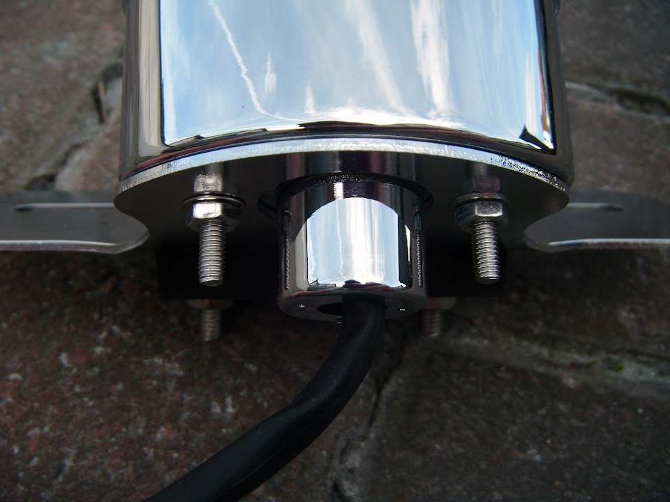
And after drilling a few holes, this is what the rear number plate light mount looked like.


This is how the light will look fixed into position.
( By fixing the light to the plate, I don't have to worry about fixing it to the body shell. )


I now need to carve out a section from the number plate plinth, so the light mounting plate will sit flush behind the number plate.


I might also have to trim the fixing bolts back a bit so they don't reach the body shell.

Then all I will need to do is drill a single hole in the body shell for a grommet & the wires.

But the real breakthrough came when I worked out I didn't need to build the body shell out to meet the light bracket.

Instead I can "simply" add three small sections of metal to the top of the bracket like this.


This was a very rough mock up so I could describe the idea I had.

I will make a proper template after I have turned the body shell the right way up to give me better access.

The plan is to weld these 3 extension pieces into place, tidy them up & paint them black.

So hopefully this will look like a single number plate light bracket that matches the contours of the body shell. :pray:

- - - - - - - - - - - - - - - - - - - - - - - - - - - - - - -

Warts & All:
I try to point out the errors I make along the way and using my new number plate to "squash" the plinth was one of them.


Or more accurately my error was not being careful enough when separating the plate from the fibreglass filler.

As when I took off the "protective" parcel tape today I found this corner of the plate was damaged. :rant:


Now I still have the oversized original that came with my donor.


But I have two questions relating to this:

How easy is it to cut these perspex number plates?
( As I want the plate to be the minimum legal width & no wider. )

The characters on this original donor plate are made up of this pattern, rather that solid black like my replacement one.


Is this still defined as "black" under the rules, or should I simply order a new plate and move on?

- - - - - - - - - - - - - - - - - - - - - - - - - - - - - - -

Overall, a pretty frustrating day in places, but on the other hand, I am slowly working my way through the jobs.

I can actually accept the fact that I go around in circles at times, as I've never tackled anything as complicated as this before.

Especially as I see all these little jobs as taking me closer to bonding on the body shell, which will be a major land mark for my build.

But that is all for today, so until next time, take care, Paul. :)
8 Mar 2015, 6:02pm
I went with the same motorcycle rear light that you're having trouble fitting Paul.

I just bored a hole for the rear extension that carries the cables (you can see it in the middle of the back end here) -


I also flattened the mounting bracket as it's angled for fitment to a curved motorcycle rear mudguard, then used the mounting bolts supplied to bolt the numberplate to it and through the shell to secure the whole caboodle to the car. Quite simple really -

8 Mar 2015, 6:06pm
Paul, as far as I know the perpex plates are awkward to cut as I believe they are laminated.

At a lot of these car shows etc, they will make up plates there and then for you in any size you wish. This may be an easier way to go, if you can find such a place.
8 Mar 2015, 6:12pm
Oh, forgot to ask: what year's your car? Can you fit black plates? They would just give it one of the finishing touches imho, I like the pre '63 riveted white plastic letters on a black alloy background myself, as fitted to the back of mine. They just give the car more of an authentic 50's look.
9 Mar 2015, 8:43am
Mr T - I definitely stole the idea of that rear light \ number plate holder from your build.
( See my Post #1676 on the previous page. )

My main concern is about sealing the hole I'd need to drill for the cable extension piece.
( Because my boot area extends back as far as the rear end of the body shell. )

My donor Spitfire was one of the "babies" of the entire Sammio family, a 1980 "V" reg!
So even though I love the look of those black rear plates, I can't legally fit them.

My plan was always to look into getting an ageless number plate if funds allowed.
Although I can't get a cheap Irish plate until the car in on the road (MOT & Tax).
Then at least reg. no. wouldn't give the age away, even if it did raise a few suspicions.

- - - - - - - - - - - - - - - - - - - - - - - - - - - - - - -

Scottie - Good point about them being laminated, as that is how I damaged this one. :rolleyes:
By chance, my donor's registration number only has 6 characters (3 Letters, 2 Number & a V).
So I had a plate made up that was only 16 inches wide, yet still met the legal gaps around the outside.
Depending on whether, or not, I get a new dateless registration, I will get another plate made.
As I can always just fix the original donor's oversized rear number plate in place for the MOT.

- - - - - - - - - - - - - - - - - - - - - - - - - - - - - - -

Change of Plans:
I was hoping to made good use of the dry weather forecast for this morning.

However, there is no escaping the fact that I have other stuff to do instead. :icon_sad:

So I'd better get on with that instead and hope I can play outside tomorrow.

Cheers, Paul. :)
10 Mar 2015, 5:54pm
More Small Steps Forward - Part 1:

Petrol Cap Base Ring:
Marked up where I wanted to give the fibreglass a bit of a trim.


Before using my Dremel "lookalike" tool to carefully nibble away at the edge.

Which gave the rubber seal a bit room to breathe.


Mixed up a little too much fibreglass filler to cover the ends of the rivets to make them watertight.

Then decided that 6 big blobs didn't look very good anyway, so just joined them up to make a filler donut instead.


Once this had hardened, I gave it a rough sanding down, as it is not going to be on show.


- - - - - - - - - - - - - - - - - - - - - - - - - - - - - - -

Wheel Arches:
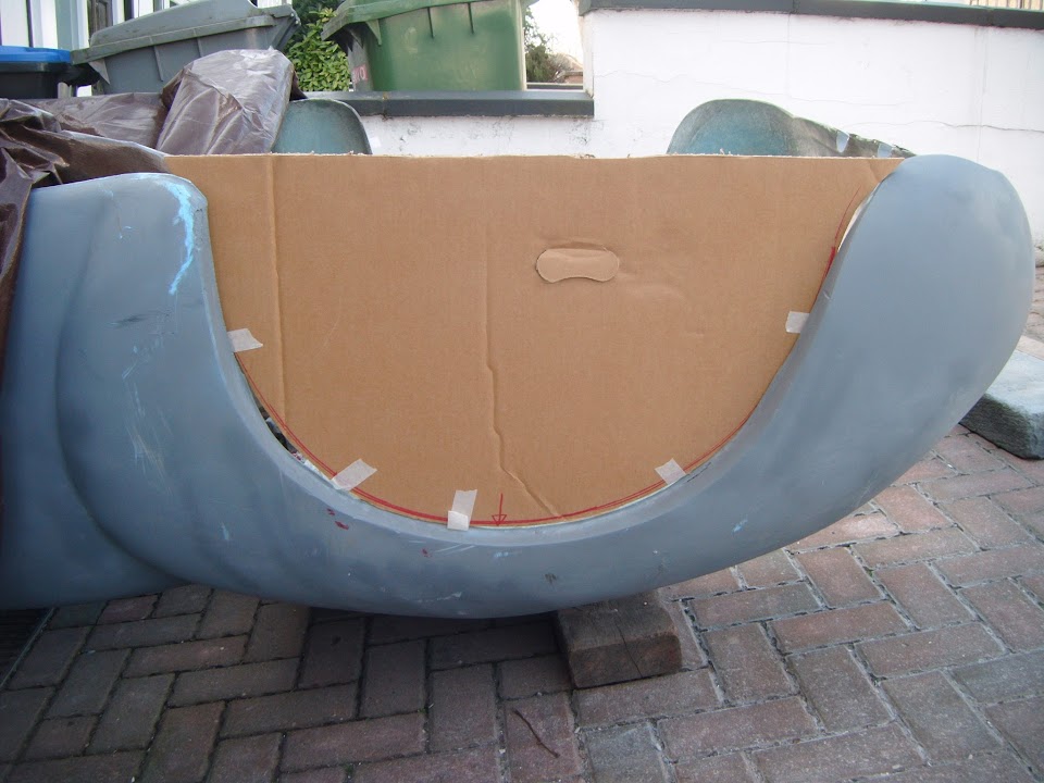
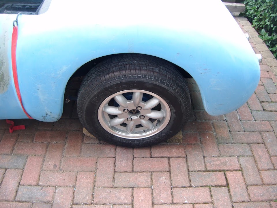
While I was waiting for the filler to set, I made a cardboard template for the passenger rear wheel arch.


I planned to use this to help me get my head around what I needed to do with the front wheel arches.

But first I did a quick comparison with the driver's rear arch.


This was actually much closer than I'd expected, as I knew the front/leading edge would be different.

With a length of wood running across the rear cockpit edge you can see why.


This is the passenger side:


And this is the driver's side.


Which also ties back to these photos I took last year showing a difference distance between the body shell and the tyre.

Passenger:


Driver:


Which, in turn, was a legacy of the HUGE difference between the two halves of the original mould.


At some point I will need to decide which would look better, shortening one side, or extending the other.

But for now, I wanted to compare this template with the front wheel arch.

The original Cordite/Navigator demonstrator also had 13" wheels and they were lost in the standard front arches.


The last photo I have of my car with the body shell on was this one.


So I used a length of wood to give me a rough guide to where the bottom of the body shell reaches.


So if my front wheel arch was the same profile as the rear, it would look something like this.


The gap is around 2 inches at the top and simply "filling in" that gap would make a big improvement. :cool:

This work is linked to extending the body shell to take the bottom edges of the bonnet.

Thankfully sorting that out and fixing the profile of the rear bonnet edge is the last of the major fixes required. :pray:

End of Part 1...
10 Mar 2015, 5:55pm
More Small Steps Forward - Part 2:

Boot Access Panel:
Got some etch primer on the "washer" in the morning.


So by the afternoon I could bond it into position.


By late afternoon, the boot lid was still "chilling out", enjoying the Spring sunshine. :cool:


- - - - - - - - - - - - - - - - - - - - - - - - - - - - - - -

Rear Number Plate Light:
I turned the body shell over, so it was the right way up.


Trimmed the fixing bolts a tad.


Marked out where the mounting plate was going to go.


Used the Dremel type tool again, plus some sand paper, to grind away a couple of mm from the plinth.
( I will add some fibreglass matting to the other side of this area, just to re-enforce it a bit. )


Just enough for the mounting plate to sit flush.


Note:
I will fit a thin rubber "gasket" between the metal mount and the number plate itself.

With the number plate pressed against the plinth, the light simply slots into place.


This is the view from above, although I still need to drill a hole in the body shell for the wires.


I also ground out a channel through the plinth, so I wasn't building a water trap.


Based on a fresh set of cardboard templates, I cut out the "extensions".
( I also drilled the two mounting holes. )


Once the four pieces were welded together I had this.


My plan is to fine tune the shape of the edges once I offer this up to the body shell again.

But for now this is how it looks with the light re-fitted.


I am sure it will look a bit better once it has been tidied up some more and painted black. :pray:

- - - - - - - - - - - - - - - - - - - - - - - - - - - - - - -

Whilst this has been a slow progress kind of day, at least it is forward progress.

So until next time, take care, Paul. :)
11 Mar 2015, 4:01pm
Very Little:
Just time to tackle a couple of things today.

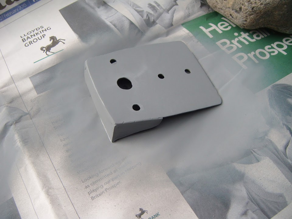
The first was to simply get some etch primer on the rear number plate light bracket.


The next was to start constructing a "splash" mould of the front bulkhead.


I hope this will eventually allow me to make a new rear edge for the bonnet.
( A sort of variation on the way Swifty's did his. )

So I added some parcel tape along the front edge.


Then just a couple of layers of fibreglass over the top for now.


As I don't want to over load it and risk parts of it sliding off the sides.

Next time I will include something to brace the mould when I add more matting.

Sorry too many other things going on at the moment.

Cheers, Paul. :)

PS
I know this mould will not give me a perfect bonnet edge, due to the slopes on the bulkhead.

But it will give me a better starting point than the way I have approached it so far. :rolleyes:
11 Mar 2015, 7:53pm
Good progress Paul! Keep at it.
12 Mar 2015, 5:43pm
Scottie - Cheers. :cool:

- - - - - - - - - - - - - - - - - - - - - - - - - - - - - - -

Another Lovely Day - Part 1:
I am desperate to make the most of this recent run of nice weather.

Marked up the damaged number plate.


Then drilled two holes and fitted some temporary bolts.


This allowed me to line up the plate and drill the corresponding holes in the plinth.


I also added a hole for the wires, which will take this grommet to make it water tight.


I knew the extension pieces would be a bit too big.


But I underestimated just how long it would take to trim this to size.
( As I was determined not to rush it and take too much off by mistake. )

Eventually I had the fit I needed.


Note:
I had to remove the light whilst using the grinder so it wouldn't get damaged.

I cut up some more of an old bicycle inner tube to sit either side of the metal mounting plate.


Then with everything put back together, the light fits like so.


Note:
The light isn't sitting straight, as I just pushed the temporary bolts into place for the photo. :rolleyes:

Next the welding on the inside edges of the extensions was covered in fibreglass filler.


When I was welding the extensions into place, one side of the top surface "dropped" a bit.

Unfortunately, I couldn't remember which end it was without refitting the light. :rolleyes:

So I just added some filler along the whole of the top surface for now.


The other areas that I applied fibreglass filler to at the same time were around the eye bolt "washer".


Plus one small section of the boot lid edge that wasn't close enough to the rubber seal.


My new rivet tool arrived today.


So I could finish off the tail pipe shields.


I must say that this new tool works miles better than my old one. :cool:

End of Part 1...