MadaboutKitcars

This is a read-only archive of the old Madabout Kitcars forum. New posts and replies are no longer possible, but every thread is still here to browse and read.

Another Cordite Is Born ...

24 Feb 2015, 12:43am
You actually need a small intake area for a rad (approx 30% of the rad area) - ideally shrouded into a divergent duct on the way in (to slow the airflow down at forward speeds - otherwise it goes through the rad too fast and doesn't have time to cool it) and a convergent duct on the back to accelerate the hot air out and create a low pressure (sucking effect) to bring more air in (although older cars tend to just empty into the engine bay and rely on the airflow below the car to extract engine bay heat).

Having said that, I agree with 8V Ed that the original stuff risked a build up effect.

love the new grille material - I have a roll of something similar that was donated to me years ago and has done 4 Scimitars so far!!
24 Feb 2015, 10:14pm
Jones - Just looking at those flames makes me feel warmer. :icon_wink:

As I look back, I think this has been the longest run of wet weather I've had this Winter.
Because I was still able to get some work done even when others were snowed in.
So overall, I've got to be happy with just how many jobs I have managed to tick off.

scimjim - I think it is fair to say I know more about air flow today than I did last week.
I also think the new grille mesh is going to give the car a more traditional look. :cool:

- - - - - - - - - - - - - - - - - - - - - - - - - - - - - - -

A Mixed Day - Part 1:
Lots of other things to do today, but with a decent weather forecast, I really wanted to squeeze a few car jobs in too.

But rather than follow a strict time line, I've grouped the jobs together for convenience.

I quickly roughed up the area along the main repair between the wing and bonnet.


It is not easy to see in the photos, but I am dealing with a couple of issues:
- Obviously the first is due to the way I re-joined the cut
- But there are also some unrelated "dips" in the bonnet too

This last point links in with the vast amount of filler work that Swifty has done on his bonnet.


So I added yet another layer of normal body filler.
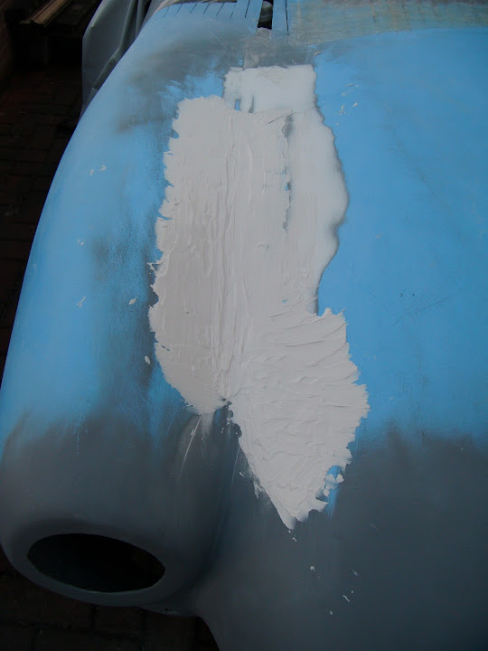


When the filler was set hard enough I stared sanding it down.
( I am not trying to get the final finish for painting at this stage, just ensure that the overall shape is OK. )
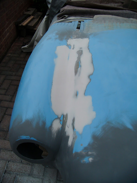


I know the 'after' photos do not look very different to the 'before' ones, but this is actually a big improvement.

Then I sanded some more of the bonnet in preparation for a dusting of etch primer.
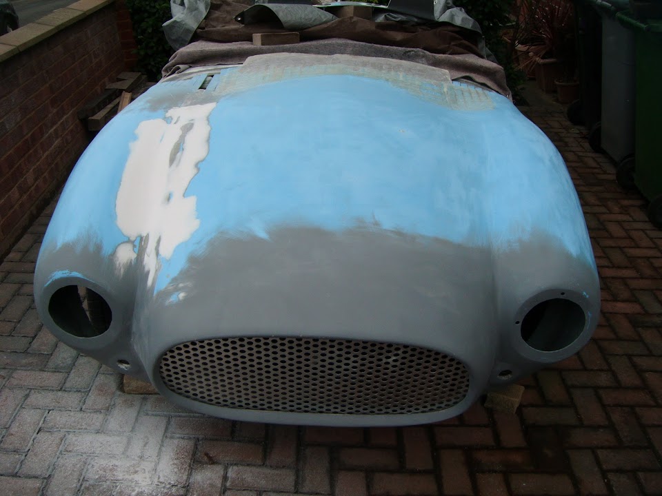


As getting the front of the bonnet in one colour would give me a better idea of where I was.

Although the gusts of wind were not making it easy to spray outside. :icon_evil:


I am not trying to create a mirror image either side of the bonnet, just a smooth transition over the repair work.

I can see why Swifty needed to do so much preparation work if he wanted a super smooth finish.

I may simply settle for the "been into the hay bales a few times" look and live with a smooth, but undulating surface.

- - - - - - - - - - - - - - - - - - - - - - - - - - - - - - -

I also gave one side of the petrol cap base ring a coat of etch primer too.


Because at some point I want to bond this into position.

- - - - - - - - - - - - - - - - - - - - - - - - - - - - - - -

I measured the distance the bonnet hinging bolts stick out beyond the nut.
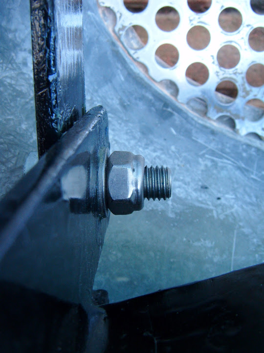


Then I experimented on one of my spare M12 bolts, by removing some of the thread with my angle grinder.
( I fitted 40mm bolts, but also bought 2 x 45mm bolts just in case. )
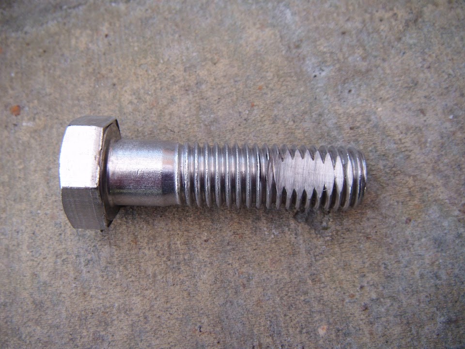


The plan was to use my new cobalt bits to drill a hole for an "R" clip to go through.

But my drill head has started oscillating slightly, which combined with my accidental application of brute force resulted in this.
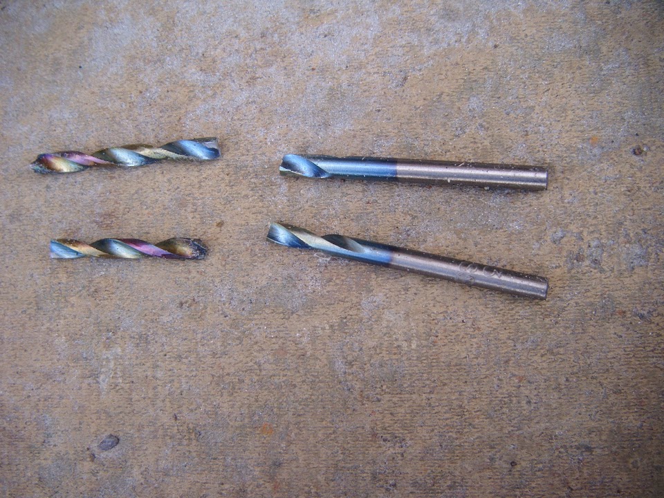


:icon_sad:

What made it worse, was that the remaining drill bits were barely making a dent in the bolt.
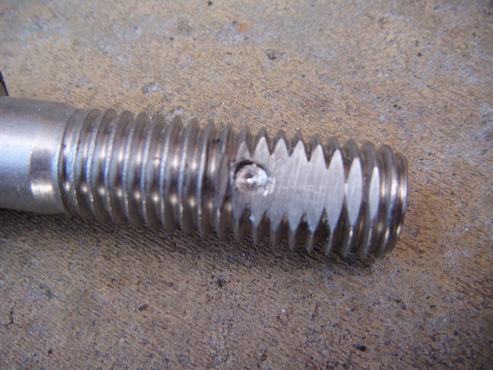


So I will put that in the "too difficult" pile for now and come back to it later.

End of Part 1...
24 Feb 2015, 10:16pm
A Mixed Day - Part 2:
I disconnected the rear wiring loom and brought it outside so I could test fit the rear lighting section in the "boot".


The good news is there should be no problems connecting the lighting to the loom. :cool:

The support bracket I built for the exhaust pipes will be a good place to attached the rear loom.


Although at this point I realised that I could not sort out the rest of the route with the body shell on. :rolleyes:


As I was hoping to work out where the wires for the petrol tank sender needed to go, but that can also wait.

- - - - - - - - - - - - - - - - - - - - - - - - - - - - - - -

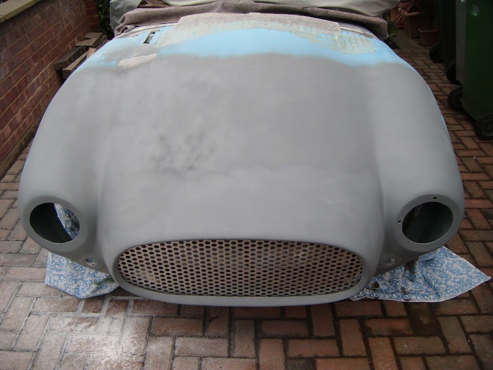
The first job I actually did this morning was to tape the "holey" grille in place so I could take a "Before" photo.


I thought this would give me a good comparison with the "After" photo when the new grille arrives later in the week.

However, this is one part of the day that turned out much better than expected as look what turned up in the afternoon.


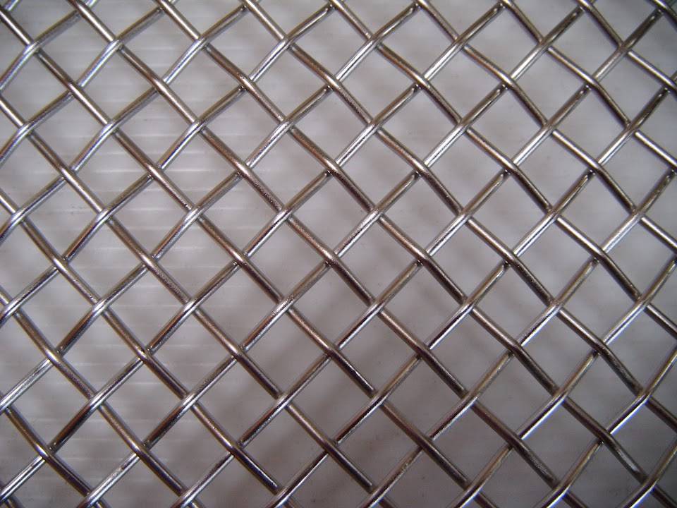
Ordered on Sunday with standard delivery and here it was on Tuesday. :cool:

I had actually popped out on an errand and came home to find it in the porch.

For most of the day the weather kept quickly switching from blue skies to this.


Unbelievably as I arrived home this time, it was actually bright sunshine and hailstones! :eek:

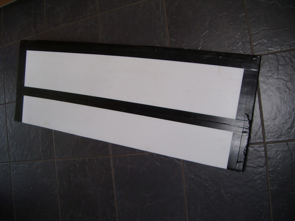
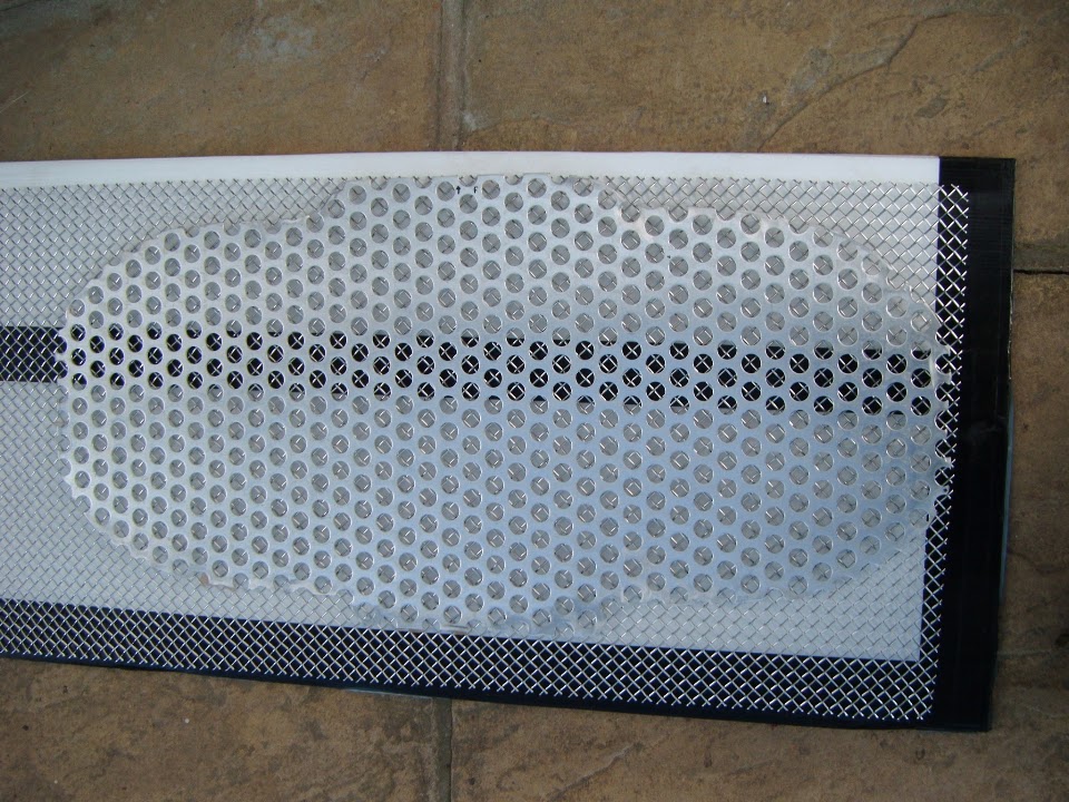
So I had to wait for my chance to cut the mesh to match the grille opening.


Then I could tape it into position to see how it looks & thankfully it looks a lot better in real life compared to this photos.
( Edit - I've replaced this first photo with another one that is slightly better. )


So thanks again for all the feedback that lead to me taking this option. :cool:

- - - - - - - - - - - - - - - - - - - - - - - - - - - - - - -

So a bit of an odd day with some good progress and a few small set backs.

However, overall, I was very happy to get the chance to do some work outside.

Until next time, take care, Paul. :)
24 Feb 2015, 10:31pm
Hi Paul, what you need for awkward drilling jobs like this is a cheap pillar drill.

I got one off Facebook for 30 quid, almost unused. My neighbour came round hammering on the door of my borrowed shed, to tell me about it. I don't do Facebook but together with my son Michael they did the deal and I collected it minutes later, a mile down the road. Gumtree, Facebook, Preloved and there is another one which I can't remember, but there are plenty of options.

The one I got was very similar to this: https://www.machinemart.co.uk/shop/product/details/cdp101b-drill-press

Not over powered but with patience gets the job done. At this stage of your build I would say it could be very handy for making brackets and drilling small pieces. I have used mine quite a bit recently. Drilling small holes by hand is dicy at best.
24 Feb 2015, 10:35pm
Paul......drill a hole in the side of a nut and use this as a drill guide.........
Drill on low rpm with little pressure and use wd40 as a coolant.
René
25 Feb 2015, 10:31am
It's a shame you're not closer Paul as i have a spare Pillar Drill of my fathers that you could have had!

BTW i think you've made the right choice with the grill as, to me, that mesh looks much nicer than the religious grill.
25 Feb 2015, 2:44pm
Thanks for all the tips, links, suggestions and offers gentlemen. :cool:

Although it might actually be cheaper to simply get the six bolts drilled out by someone else.

But there is no great rush at this stage, so I will keep my options open.

Apart from taking a better photo of the grille this morning (see edited post above), no car work for me today.

I have ordered another heavy duty tarpaulin, which will be required when I strip the car back to the chassis.
( Along with permission from my wife to steal her parking space for a while. )

Unfortunately, I have remembered that I need to sort out the boot access panel before I remove the body shell.

So finally sorting out the locking pins, or fitting alternative catches will be my next job. :icon_sad:

Even though I am not looking forward to this, it has to be done.

Until next time, take care, Paul. :)

PS
I had another good look at the mesh grille this morning and it really does look the part. :cool:
25 Feb 2015, 3:19pm
The grill looks very pro...........and you can use the leftovers for the bbq....or make brussel waffels.........
About the bolts,pre-drill with a center drill............
René
25 Feb 2015, 4:24pm
Brilliant job on the grille Paul! Good choice of material.

If the car overheats now it won't be the fault of the grille!
25 Feb 2015, 7:46pm
Paul, can you remind me why you are planning to drill the bolts to fit 'R' pins?

If it's to stop them coming undone, then use locktite, or locking 'Nylock' nuts or even two nuts tightened against one another. I don't recognise the need to lock a bolt with that level of security, even on a vibrating roller!
25 Feb 2015, 10:06pm
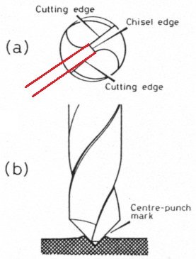
Paul the advice i can give is that you really need to hold the bolt or any round item you intend to drill in a vice putting a flat on first is a good idea if drilling by hand with a pistol drill (pillar drill with a clamped vice is far better and safer) but also use a center punch where you intend to drill and take it easy with the pressure as a sharp drill should do the work, whilst on the subject of drill bits a good quality high speed steel or as it commonly know HSS drill will be ok, i use these every day to drill stainless steel as well as other metals and find them great only need to sharpen when the cutting edge is knocked off, also use a lubricant while drilling just a little bit at a time, you can buy cutting fluids specifically for different metals but as an easy alternative at home WD40 or engine oil is ok and you will keep the drill bit sharper for longer, you will get smoking when the oil becomes hot but don't worry it's normal and some of the specific cutting fluids have an awful smell.

What i also do is drill a pilot hole first as it's easier to drill large holes this way (give it a try and i guarantee you will see how easy it is especially drilling steel or stainless steel), by pilot hole i mean measure the chisel edge of the final drill size for the hole required and use a drill equal too or 2/3rds the chisel edge length to drill a pilot hole then drill the hole to the size required. I've outlined what the chisel edge is in the drawing below.

drill.jpg


The colbalt drills are brittle compared to HSS but also if you put too much pressure on the drill bit while not holding the part securely and start to wobble the pistol drill then its a recipe for disaster especially the smaller the drill bit is. Some good info here http://http://en.wikipedia.org/wiki/Drill_bit

One thing to remember is we all snap drill bits from time to time the worst thing to snap in a job is a tap as is means you either have it spark eroded out or start the whole job again which is a real pain so i reality a couple of snapped drill bits is nothing.

Keep up the great work Paul as not only will you have a fully functioning car on the road built by yourself but also a wealth of knowledge in all things mechanical which i bet four years ago you never dreamed of.:smile:
26 Feb 2015, 9:30am
ReneAnglia - Unfortunately, this is only drill I have and now it seems to be "wobbling" on me. :icon_sad:


Scottie - Unfortunately, the grille pattern seems to cause "interference" when I try to photograph it. :rolleyes:
But it does look really good in real life and I am happy to have reached the right place in the end.

8 Value Ed - The problem I have comes from using a bolt as the hinge pivot in the first place.


I need the nut to be tight enough to lightly "squeeze" the two halves of the scissor bracket.
( This has the effect of "dampening" the bonnet opening, otherwise it would really "snap" open. )

The problem seems to be that one half of the hinge tries to undo the nyloc nut when the bonnet is opened.
So my "simple" plan was to use the "R' clip to limit the distance the nut could move.

However, I will also try the double nut approach and maybe add some extra washers as well.

Swifty - Thanks for the detailed reply and you are certainly right that I am learning a lot on this build.
As I don't have a vice, pillar drill, or even a workbench, it would be safer to get someone else to do this for me.
Given the amount of work I have actually done myself, getting some help to drill 6 holes doesn't seem too bad.

- - - - - - - - - - - - - - - - - - - - - - - - - - - - - - -

Weather Watch:
Another wet and miserable day here at the moment. :icon_sad:

But I might be able to start looking at the boot access panel late this afternoon.

Cheers, Paul. :)
26 Feb 2015, 9:41am
Take it off hammer... :badgrin:
26 Feb 2015, 9:42am
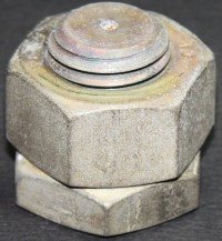
Paul if you use the double nut lock principle then i think you should be able to get the correct amount of friction and if in the future the brackets wear you can re tighten the nut's again.

Here's an image of the double nut principle, you tighten the nuts up against each other. You don't have to have a shallow lock nut use two of the same depth.

twonuts_thin_nut_onbottom.jpg
26 Feb 2015, 5:43pm
GaryH - Cheeky git! :icon_wink:

Although based on previous "lessons", I not only check it isn't in hammer mode, but also not in reverse. :rolleyes:

Swifty - Thanks again, see below.

Rene - Sorry, my mistake, a lot of this is new to me.

- - - - - - - - - - - - - - - - - - - - - - - - - - - - - - -

On a KISS roll...
I used the damp weather outside as another excuse to tidy up the Summer House for the umpteenth time.

Before:


After:


While I was tidying I found some nuts and bolts for the two car horns & packed them away at the same time.


I also I left out my 45mm M12 bolts and the nyloc nuts they were supplied with, plus some spanners.

So when it was finally dry enough, I could try the KISS "double nut" approach on the bonnet hinge.

First I had to prop up the bonnet so I could remove the bolt without it dropping.


Then it was a pretty straight forward swap for the longer bolt and the two nyloc nuts.


Well it was straight forward on the passenger side...

As the fibreglass repair work on the driver's side made it a little tricky to remove the old bolt.


But after much swearing and grazing of knuckles, the old bolt came out & the new bolt went in.

It was quite hard to get a decent photo of the two hinge bolts in place, so this was the best I could do.


A quick check showed that the bonnet still has a "damped" opening action, so all is good. :cool:

Thanks again for the double nut suggestion, much easier than trying to drill a small hole in a bolt!

- - - - - - - - - - - - - - - - - - - - - - - - - - - - - - -

Although it had stopped raining, the skies were still black, so I switched to working on the exhaust shields.

First I made a slightly more symmetrical template.


Then I marked up some sheet metal.


Before using my jig saw to cut them out and my angle grinder to tidy them up a bit.


Note:
I will be trimming the inside edges of the shields to match the body shell.

Also, if you look closely at the last photo you will see the first drops of rain that were my signal to call it a day.

I still need to drill out some rivet holes in these shields and shape them to match the bodyshell.

So until next time, take care, Paul. :)
27 Feb 2015, 5:39pm
Boot Access Panel:
I wasn't looking forward to peeling off the car covers and having another attempt at getting these locking pins to work.


But as it is the last major stumbling block to making some real progress on this build, it had to be done.

I started by removing all the locking pins.


Then I spent a lot of time looking through the holes seeing if everything lined up & trying to work out what I was doing wrong.

I also tried to locate the holes using the fixing bolts and this gave me an idea, which involved taping the lock to the bolt...


As it occurred to me that previously I was fixing one part into position & then fixing the other.

I could get this "combined" bolt into each of the holes in turn, so I refitted the locking pins & taped all the bolts in place.


The good news was that all four bolts slid into place with a little bit of a wiggle.

The bad news is that it is this requirement to "wiggle" the bolts to fit that is causing the problem. :rolleyes:

The sad fact is that all the curves and angles in both the panel and the boot opening are impossible to line up in an operational way.

OK, let me clarify that a bit, they are impossible for me to line up. :icon_sad:

So there is no point in fitting a system that runs the risk of being either unable to close, or worse, unable to open.

Therefore in the spirit of KISS which has worked out quite well lately, I am abandoning the locking pin idea.

Unfortunately, the alternative quick release pins I bought won't work either.


As the mounting plates for the bolts are outside the rain channel.


So the holes around the pins would simply let water into the boot, which would defeat the all effort I put into making the boot seal.

I also had another look at the possibility of using this type of lock too.


But there is simply not enough space for them to work without major re-working of both the boot opening & the lid.

So all in all, I spent a lot of time and thought today just to confirm that I need to go back to the drawing board. :rolleyes:

Previously I talked about using this style of external catch, which can be locked.


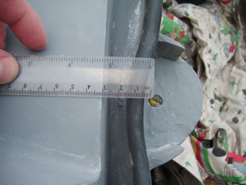
I just need to double check the measurements of the mounting points on the various catch sizes to avoid the rubber seal below.


However, in order for that approach to work, I will need a way of "locating" the boot lid into the right position.

Hopefully I will be able to re-use the mounting plates for the locking pin bolts & "just" add something to the boot lid for it to locate in.

This is something I need to put a bit of thought into, but off the top of my head, I could bolt these to the body shell.


Then I could take a fibreglass mould from the cone and 'glass it into place on the lid.

Hopefully that would allow the lid to sit in the correct position, before the catches then keep it there.

The other thing I will need to do is lower the rain channel edge that the rubber seal sits on.

As despite the seal being squashed by the lid all Winter, the boot lid still sits a little bit too proud.

So while I don't feel I have made much progress on one hand, on the other I think I can see a way forward.

I will certainly be very glad when this boot lid is finally sorted out.

Until next time, take care, Paul. :)
28 Feb 2015, 5:04pm
Another miserable day here, so not much to report...

Passenger Side Mirror Pedestal:
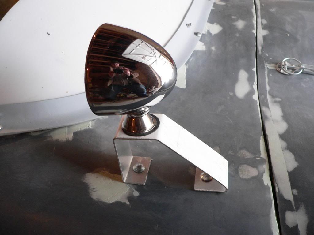
This was how I originally fitted the passenger side mirror.


But I want to mount it on a pedestal for two reasons:
- It should make it a functioning mirror, rather than a shiny decoration.
- My making one side different to the other (I'm leaving the driver's side mirror as it is) it adds to the overall lack of symmetry.

If I want to stick to KISS, then there are two basic options:

Make the bracket work inside to out, like this C Type Jag:


But I am going to follow Mister Towed and make it front to back:


With hindsight I would have been better off ordering side mirrors with a single bolt, but such is life. :rolleyes:

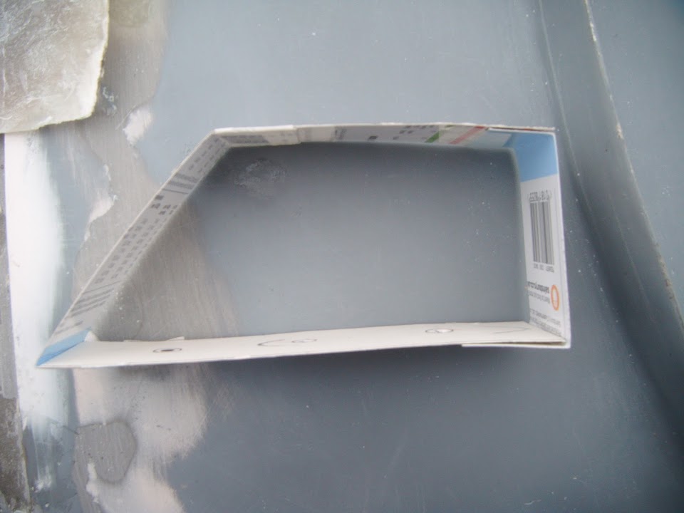
So I started making a cardboard template for the mirror to bolt to.


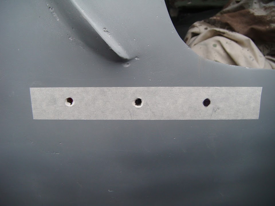
Next I went back to the two holes in the body shell.
( Because these line up with the mirror on the driver's side. )


The base will be longer than the top to give a slope at the front, so I could add an extra mounting hole.


Thankfully I spotted this might be in the way of people climbing in over the side.

So the MkII version puts the extra hole in front of the existing two holes.


I did check and there is no access problem on the other side of this extra hole.

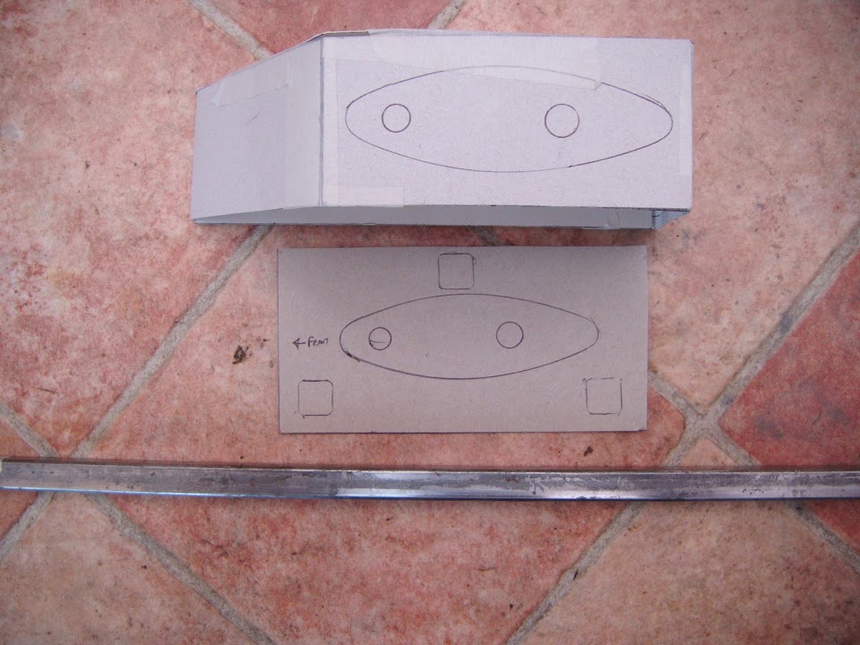
Next I made a template for the base.


Unfortunately, the curve of the body shell makes this job a little more complicated.

The basic shape of the pedestal will be something like this.


But I can't bolt something like that to the side of the car, or this will happen...


Completely useless!

So I need to shape the vertical sides of the pedestal to blend in with the side of the body shell, something like this.


However, if there is an angle here, then the base needs to be wider to join up properly. :rolleyes:


Given my sloping drive, I can't set this angle until I have the body shell off the framework.

But at least I now have a better idea of what I need to do.

I also know that I can make three sides out of a single piece of metal which I will need to bend.

Then I can weld the base section into place and add a bit of bracing here and there.

As long as I can still get to the various bolts I should be OK.

Thanks all for now, take care, Paul. :)

PS
I've ordered the external catches for the boot lid & have a pretty good idea how I can "locate" the lid. :pray:
1 Mar 2015, 5:29pm
Odds & Ends - Part 1:
Yesterday I spent a bit of time looking back at the photos of my cardboard template for the mirror pedestal.

Then it dawned on me that I might be barking up the wrong tree with this "simple" design, which was going to work something like this.


I posted a photo yesterday that showed how I would have to extend the back of this bracket to match the curve of the body shell.


But I didn't think about the front edge yesterday.

It would be quite tricky to do the same thing here without it looking like a dogs dinner.


So this approach is not quite the KISS solution I had in mind. :rolleyes:

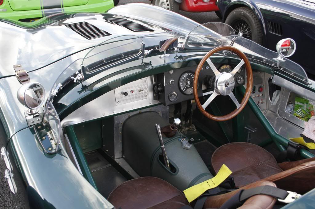
This meant going back to the drawing board again and I found these photos on Google Images.


A variety of styles here, many from the "function over form" school of design / pit lane adjustments.

So I have a brief look at an option that would use some of the small box section I have available.


If I made the mirror mounting plate a little bigger & made 3 box section "legs", all I would then need is a base plate for the body shell.

Something like this.


This would have the added advantage of retaining the two holes in the body shell, thus making this bracket an optional extra.
( Giving you the choice of fitting the mirrors with, or without it. )

Although looking at the photos again, I might have to include a small vertical edge around the mirror mounting plate for safety.

Note:
As always, I am open to feedback and suggestion about this approach to mounting the mirror.

In fact, part of me is tempted to put this in the "nice to have" pile and only come back to it when the rest of the car is done.

- - - - - - - - - - - - - - - - - - - - - - - - - - - - - - -

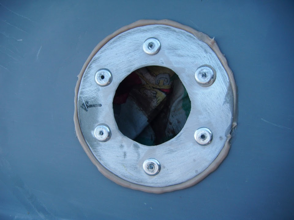
Anyway, for today, my next job was to fix the petrol cap base ring, so I made sure there was a dust sheet underneath the hole.


Then I mixed up a small quantity of bonding paste and spread it all around.


Then when the rivets were used, it squeezed out any excess paste like so.


Later on, when the paste was set solid I trimmed it off with a sharp blade.


One thing to note was just how much effort was required to "pop" the rivets, I thought I was going to burst a blood vessel. :eek:

Unfortunately, this meant that not all the rivet pins came away cleanly.

They should all look like this.


But most of them few ended up looking like this. :icon_sad:


End of Part 1...
1 Mar 2015, 5:30pm
Odds & Ends - Part 2:
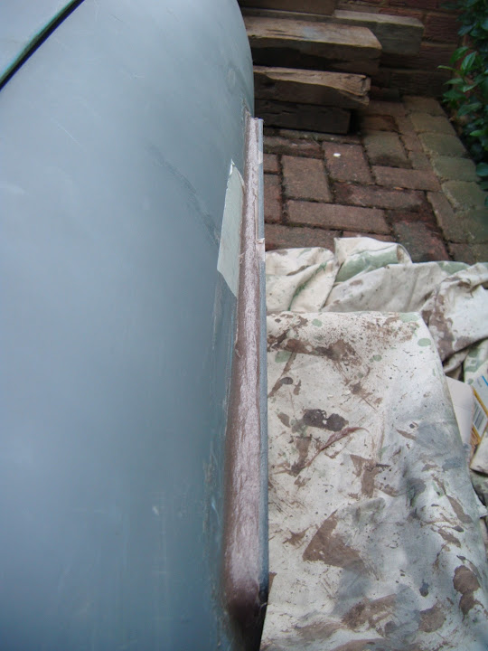
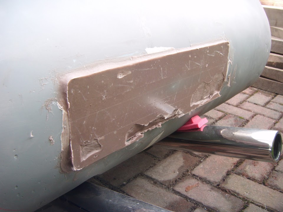
My final job for today was to make a plinth for the rear number plate, as there is no where for it to sit flush.


I put some parcel tape over the reflective side of the rear plate and used that to squash the fibreglass filler I had applied.


By chance I had mixed the perfect quantity of bonding paste for the petrol cap base, but lightening didn't strike twice with the filler. :rolleyes:

As it turned out, not only did I not mix enough, I also moved the plate when I realised that I have aligned it horizontally, but not vertically.

Shoving the plate upwards to fix this left a few holes in the bottom section, but I didn't notice until after I removed the plate. :frusty:

Obviously I had to wait until the filler had set pretty solid before I peeled it off & this is what I revealed.


I will leave this to set fully before I "top up" the filler and create a solid base to mount the number plate.

I'm sure that by the time I've finished sanding it and give it a coat of etch primer it will look much better.

- - - - - - - - - - - - - - - - - - - - - - - - - - - - - - -

Whilst I didn't get the chance to do more today, at least this is another step in the right direction.

Plus given how hard the rain is currently lashing down, I was very lucky with the weather earlier. :cool:

Until next time, take care, Paul. :)
1 Mar 2015, 6:51pm
Paul i think you're right with barking up the wrong tree..........
My honest opinion about the pedestal...............it looks like a bob the builder solution........
Go for the tripod solution like the no.2 ferrari(wich has two stacks).........using a tripod system makes it easier to adjust
René
1 Mar 2015, 7:23pm
I think it's neat, I just cringe at the added weight! I would grind out the centre leaving the periphery and pillars where the bolts are so the plate isn't crushed in with the pressure. Maybe build the plinth out a little and blend into the main panel. Would look very 'finished'.
2 Mar 2015, 7:51am
Paul, I must offer my condolancies to you on the death of the boot fixing idea!
I know how long you worked on it, and must feel frustrated.

I have been up blind ally's myself, and its not nice. Console yourself with the thought that at least now you will not waste any more time on it.

Perhaps you could use two flat locating lugs at one end and one locking device at the other? maybe even straps?

Or even a set of external hinges at one end?

Reference the snapping of the rivet shaft, don't worry about it, quite a few of mine went the same way! At least they are real rivets!
2 Mar 2015, 11:30am
Rene - See below for my latest attempt at being a bit more Ferrari.

8 Value Ed - Given all the other over engineered metal I've added, the mirror mount will not make too much difference. :icon_wink:

Scottie - Cheers, I plan to use a combination of both internal locating pins and external (lockable) catches.

- - - - - - - - - - - - - - - - - - - - - - - - - - - - - - -

Flying Visit:
Did a bit more tinkering this morning, before other chores take up the rest of my day.

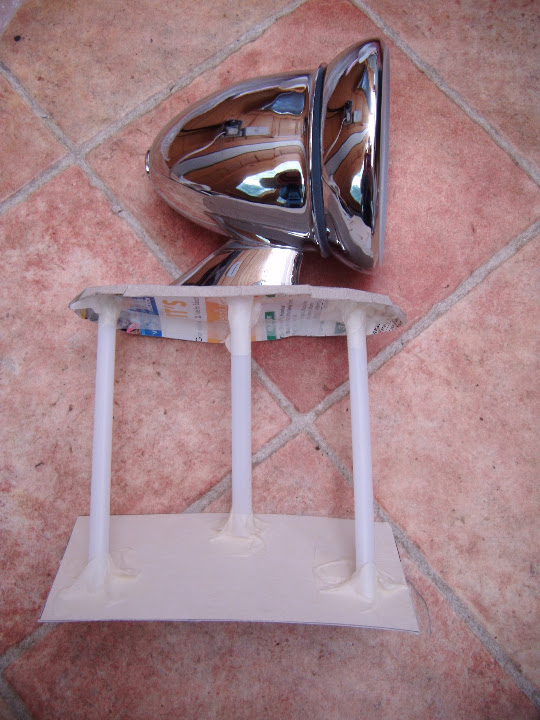
I had another think about the mirror pedestal and decided that using square edges & box section was not helping.

I do have some steel tube I could play with, but this might be a bit too big, although I could get a smaller diameter.


I could also use a more "organic" shaped based with a lip to avoid a flat edge "hazard".


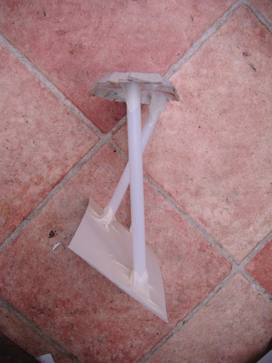
I used some thin plastic tube for the mock up.


Looking at the last photo, I could move the top of the two "outside" support tubes inwards a bit, to create more of a cross brace.

But as I said yesterday, I think I might just leave this design to one side for now & get on with other things.

- - - - - - - - - - - - - - - - - - - - - - - - - - - - - - -

Then I went outside, where despite being sunny the wind was making it feel bitterly cold. :eek:

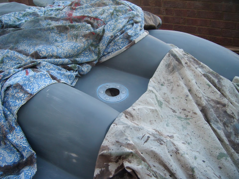
I tidied up the petrol cap base ring.


Then prepared the area for a bit of etch primer.


Although this last photo has highlighted the fact I need to trim some bonding paste off one of the rivets. :rolleyes:

- - - - - - - - - - - - - - - - - - - - - - - - - - - - - - -

The final job for the day was to roughly sand down the rear number plate plinth.


Then I added some more fibreglass filler to build up the "holes".


I will finish tidying up the bottom edge of this plinth when I have removed the body shell.
( As it would be a lot easier to see what I am doing with the body shell turned upside down. )

- - - - - - - - - - - - - - - - - - - - - - - - - - - - - - -

I didn't think I would get anything done today, so I am happy with a little progress. :cool:

But I've really got to go now, cheers, Paul. :)