This is a read-only archive of the old Madabout Kitcars forum. New posts and replies are no longer possible, but every thread is still here to browse and read.
Possibly going to make a tubular frame for the bonnet to strengthen it and help in the hinge mechanism also maybe run a tubular ring around the cockpit edge.
Lol great minds think alike (or is it fools never differ?). Check out my build update tonight! I'm doing exactly the same sort of thing. Basically making a tubular frame that bolts to the bumper and another one bonded into the bonnet, both frames will have 2 rod ends so that I can adjust the bonnet in pretty much 3 dimensions by screwing the rod ends in and out and adjusting the size of spacers between them.
BTW I have checked next door and there are 2 bonnets but no body tried to peak through the windows but got a crap angle so couldn't see if there was one being laid up. Not to say it hasn't already been done and despatched though
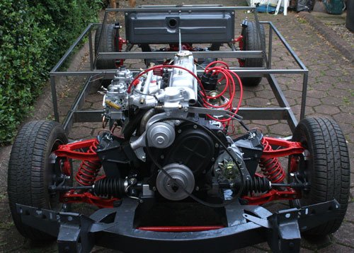
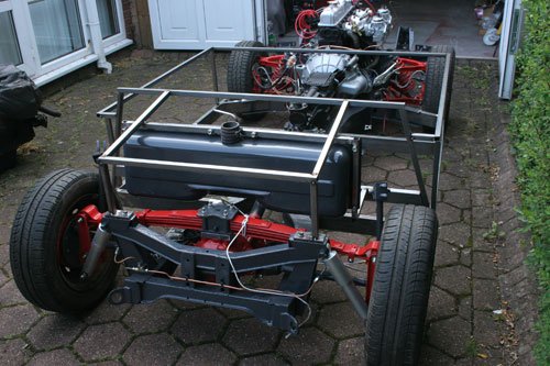
Started fabricating the sub frame before the arrival of the body.
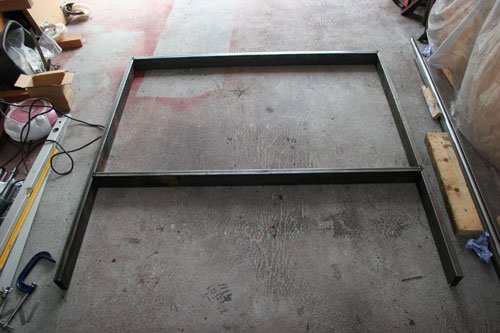
Welded up what will be the base for the sub frame to sit on, used 75mm x 25mm x 2mm rectangular box section, four lengths cut to 1320 mm. I decided to weld up as one to make it easier to work out where to cut and mount onto the chassis, next image shows this.
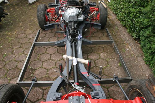
This image shows the base clamped to the underside of the chassis. After taking various measurement to make sure the frame sat square and in the right position i then marked the four places the frame will be cut.
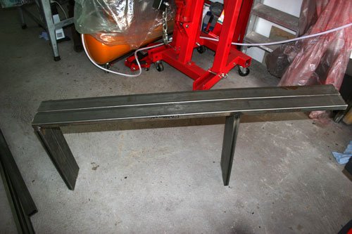
After cutting the frame in two i placed them side by side to make sure they are identical so that the frame is as symmetrical as i can make it once fitted to the chassis. The passenger side frame has a notch cut out in each leg to allow the fuel and brake pipes to pass through.
Frame fitted in position ready for the next stage of the sub frame build which will be tomorrow.
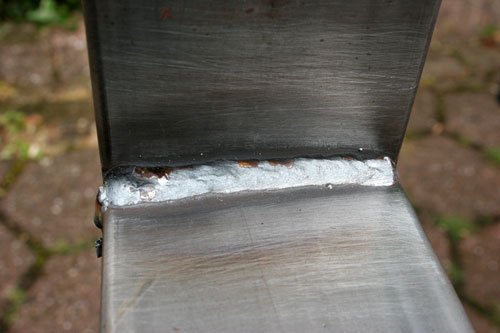
Its mig welding as i don't have a tig in the garage plus mig is fine for mild steel box section. I would only real use tig if the weld was on show with stainless or ally.
A note for anybody who has a GT6 engine is the clutch slave cylinder is the same as that fitted to a landy defender 2.5 but the landy cost's £7 and the replacement from a triumph dealer is £26.
The original cylinder bore was 1'' which is no longer available and has been replaced with a 7/8'' bore, just thought i would post this as its a saving and the triumph dealers are way over with their price.
The steel for the sub frame arrived yesterday so today i am going to fabricate the frame which should be fun, i have a rough sketch off Andy at Ribble HQ which i will use as a guide and adjust as i progress but if any body has any advice feel free to let me know.
A question for those guy's out there who have fiber glass experience - Is there a particular way that steel is bonded to the fiber glass so it becomes part of the fiber glass panel for example the bonnet area.
Thanks fot the tip concerning the slavecylinder.
I still have clutch problems:
-new clutch assembly
-overhauled slave-/mastercylinder
-changed pedal so there is no clearance problem between pedal and
mastercylinder.
-many bleeding sessions
....and still it works good when motor is cold(altough Ineed to push pedal
very deep!),but when its warm it barely disconnects!
Would there be any change fitting a Landrover slavecylinder(bigger bore)
changing anything?
When you say it works when cold but not when hot suggest there is an expansion issue but first is the condition of the clevis pin on the master cylinder ok (no play on the clevis pin or push rod.
Did you fit a complete new slave cylinder or just new seals, they are pretty cheap to buy so i would replace rather than repair.
Was the clutch release bearing carrier ok, i.e. the two pivot pins on the lever arm not worn or the groove in the release bearing carrier where the two pins locate, i had to reposition the point the two pins located into the bearing carrier as both the pins (built up with weld and re-profiled) and ring were worn, this only applies to the GT6 clutch.
Just out of curiosity have you got access to the point in the bell housing were the clutch slave is so you can measure the pin movement when cold and then hot to see if you can pin point if the movement changes.
Not sure what you mean by changing to a bigger slave bore as the original GT6 was 1 inch and the replacement is 7/8 inch which is smaller, this will give a slightly heavier clutch pedal but greater slave cylinder movement due to the fluid ratio change, if that makes sense.
Today i just about finished the sub frame apart from running out of 20mm box section so will have to order more next week, moon buggy stage nearly there.
I may alter the frame once the body has been test fitted, hopefully next weekend.
Paul L Not sure at the moment so i will be adding a frame to the rear just in case and also adding extra box section to strengthen the frame in certain areas plus i will need to work out what to do for the steering column.
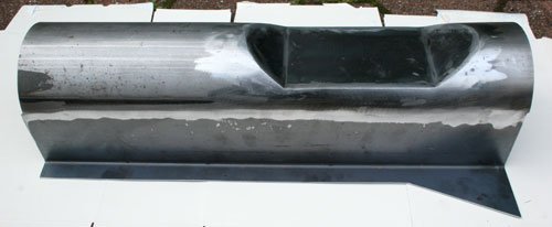
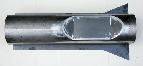
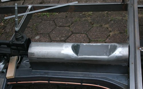
Today i finished the prop shaft tunnel.
I used a length of 5'' mild steel pipe, split it in two with a plasma cutter, cut the two sides from 1.5mm steel plate and welded into place. The top cut out profile was cut and a card board template used to transfer onto steel plate which was profiled out and welded into place, ground up and job done.
Tunnel laid into place which will look good once coated in a finish. Just need to drill various holes and add the cable entry pipe which i will do once i have manufactured the hand brake handle mount from ally, hopefully have that finished this week provided machine is free.
Jerome I hope the slave cylinder works and thanks for the comment.
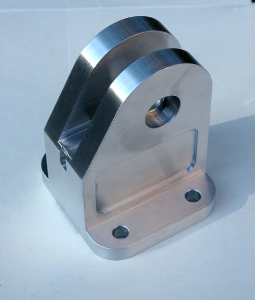
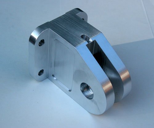
Finally finished the new handbrake mount bracket which took a little longer than anticipated. I did a rough sketch then adjusted to suit to what i thought would be ok.
I decided to machine it from a block of ally as fabricating it from separate parts would of made the job longer and its a lot easier to let a machine do the work.
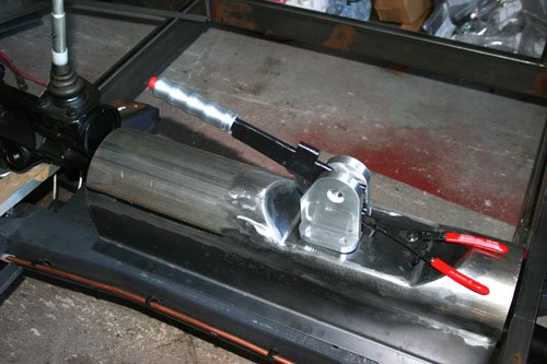
Bracket and handbrake positioned to see if all was ok, will be able to make a permanent fix once the seats are in place so i can gauge the final position.
Made a few other odds and ends while i wait for the tub to arrive.
Found a great video on the Millie Miglia, if you like old classic cars, beautiful scenery and the Italian language then you will enjoy this http://www.youtube.com/watch?v=G0eIVfr5Dck
I did and the hour and a half it runs goes over quick.
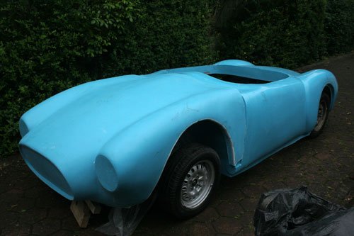
The body arrived this afternoon and managed to roughly fit it to the chassis to try and give me an idea of what is required to make the shell symmetrical.
Cut the bulk head to fit around the bell housing so that the tub sat onto the sub frame then loosely fitted the bonnet which slightly fowls the original bonnet hinge brackets, i think these will have to be removed soon.
The original wheels are still fitted as i need the hub adapters to fit the 14 inch spoke rims. The wheel centers were used as the datum points to get the body as close to a correct position before looking at the alignment issues.
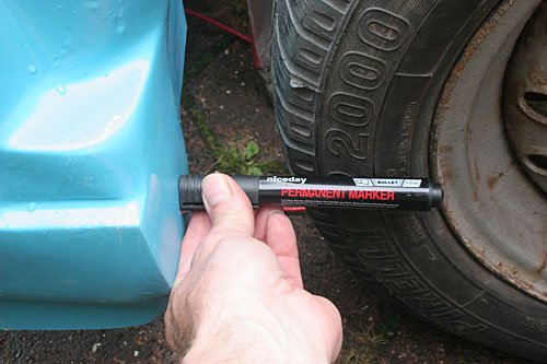
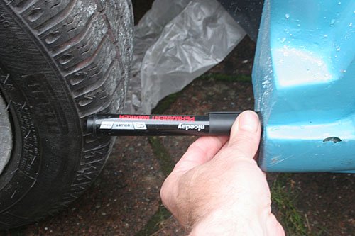
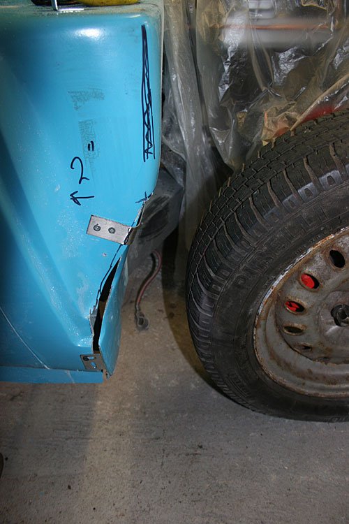
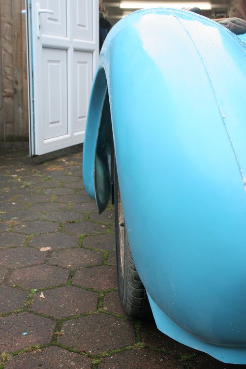
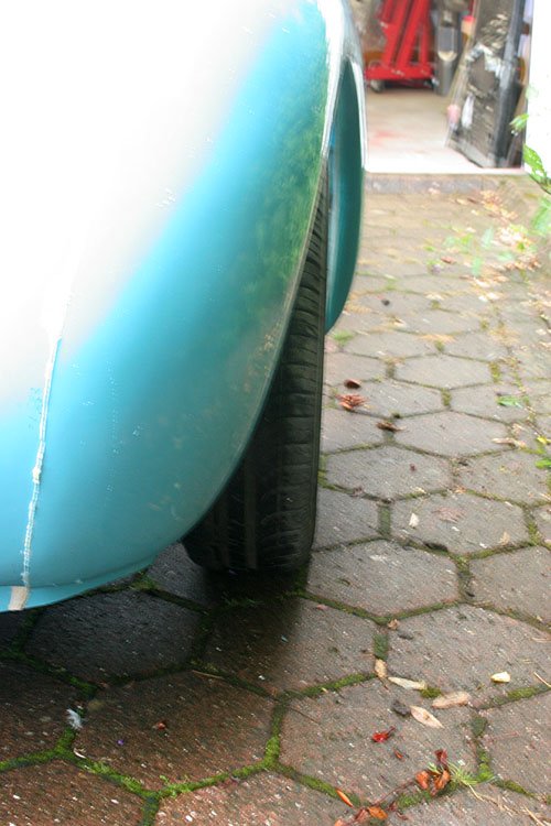
One area that requires attention is the drivers side lower bulk head. The first image illustrates the bulk head to tyre gap on the drivers side and the second image is the passenger side, you can see there is a considerable difference of about 50mm. After checking various points on the shell to find where the problem lay i decided to cut away some of the drivers bulk head which will prevent the 14 inch wheels from fouling the body.
Body now cut with the flap roughly pulled in so as to be able to glass the gap up which will be my first attempt using fibreglass.
Tomorrow paying a local supplier of fibreglass a visit to purchase a few supply's.
Another area that requires slight alteration is the rear wheel arch leading edge.
The first image is the passenger side which sticks out a good 60mm further than the second image shows of the drivers side.
I have a few questions to the old hands at fibreglassing. Around the body are a few things that i am not too sure about.
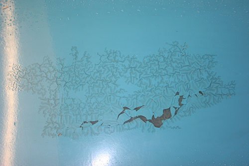
This looks like the gel coat colouring has reacted to something and crinkled up. The outer surface has a clear coat over it but should i do something to this area to prevent any further issue once a layer of paint has been applied or is it ok to leave as is.
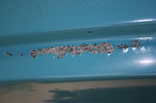
This area had a bubbled surface which i removed to reveal the glass mat below which looks like it had not been impregnated with resin. My question here is do i fill in with fibreglass filler or gel coat or is there something else required.
I was thinking that to start with 10Kg 300g csm and 25 kg resin will be more than enough to make the body good or is this not enough?
I am now starting to think ahead about bonding the body to the chassis, i have looked at two products to use as a cushion between the body and frame the first is polyurethane PU40 sealant from Tool station for £3.92 a tube and secondly Roof and Gutter mastic from tool station for £2.10 tube. Both don't fully dry out so remain flexible but i am more drawn to the polyurethane product as it mentioned it's used in the caravan and auto industry.
Has anybody used these or another product.
Swifty,
1. The rear quarter stretch is covered in my build thread ill try and find where and post a link.
2. The reacted area will be fine if just sanded down and a light skim with some bridging or flexible filler.
3. The dry area, if its not all the way through then again just top it off with bridging filler. If its dry all the way through then try and bleed some resin into it.
4. I use PU adhesive a lot in all my builds it is very very strong and flexible. Gets my vote. Glad you got your shell. Did you get an invoice with it? you'll need it for submitting the paperwork.
Yes i did get an invoice from Andy as that went through my mind also about proof for DVLA.
When keying the fibreglass surface what grit do you recommend.
Thanks for the link to your solution, so you pulled the drivers side rear wing out, i can see the difference in my photos from one side to the other i had thought about pushing the passenger side leading edge in also as the way it sticks out on my body does not look good. Will have to give it some more thought. Is the green stuff fibreglass filler?
From the photos it looks like you can really see the difference between the new body shell buck & the old bonnet one.
( My body shell looks more like your bonnet. )
Sorry I can't help much with your body shell alignment issues, given the wholesale butchery going on in my build.
Mac had already covered the other surface questions you had, but I can confirm the green stuff is this...
As I bought the same stuff as Mac uses.
The other point to bare in mind when ordering the resin is it's recommended life span of 3 months.
I've only just finished the first 5kg roll of CSM I bought and you've seen how much work I've had to do.
So maybe start with smaller quantities to begin with and see how you get on.
Paul, I wouldn't worry too much about the resin age, the stuff I used at the weekend was at least 3 years old! it set up just fine, if your resin is a bit old just make sure you mix it thoroughly before dispensing and sometimes warming it up a bit will make it easier to mix up.
HTH
Mac
Swifty, I usually use 80 grit to scuff things up before glassing. I also make sure I wipe the area down with Acetone 3 or 4 times in quick succession before glassing sometimes it will soften the surface of the surrounding area that you will be bonding too. Just make sure its had enough time to flash off before you start.
Paul Thanks for the info by the time i read your comment i had already bought 25kg of resin so i hope it shelf life is longer than a couple of months.
Viatron Thanks for the info, i did wipe the surface down with acetone after roughing it up. When i was in my local fiberglass supplier John Dickens walked in so i asked him a few questions and in the conversation he mentioned that when bridging a gap with csm the edges are chamfer so that the mat get a good hold.
A question about the body side lower edges, what you would call the sills. Is the flat edged of the fiberglass that runs along the bottom supposed to fasten to the steel section of the sub frame, or is this flat edge removed and fiberglass wrapped around the steel section onto the body lower surface.
The reason i ask is to me the body will sit high if the flat edge of the fiberglass is used to fasten the body to the sub frame.