This is a read-only archive of the old Madabout Kitcars forum. New posts and replies are no longer possible, but every thread is still here to browse and read.
In that case Garyh i found it easier if the piston was pushed as far into the caliper as is possible, the rubber dust seal sits in the piston groove and also rest down onto the caliper body if that makes sense.
The retaining dust seal ring can then be eased over the rubber to grip the caliper body, i maybe should of taken a few photos as it easier to explain with pictures than it is with words, as they say a picture speaks a thousand words.
One more thing you mentioned splitting the caliper body, if you do make sure you retain the small black rubber seal that sites between the two halfs where the brake fluid passes, you don't get a new seal in the caliper repair kit.
i have pushed the piston all the way in... when they say use some brake fluid when rebuilding... is this just to put the piston through the large O ring seal? maybe everything is getting a bit slippery.
Sorry to butt it, Gary if its all getting a bit slippey use some aerosol brake cleaner to clean off the fluid on the outside, as long as the piston and seal are all the way home you wont get it anywhere that will damage it as the first time the piston moves out it will wipe brake fluid on the cylinder wall anyway.
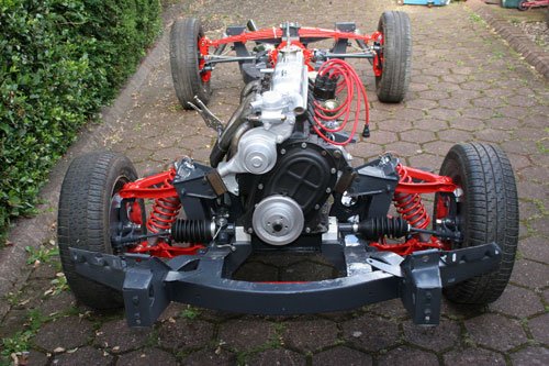
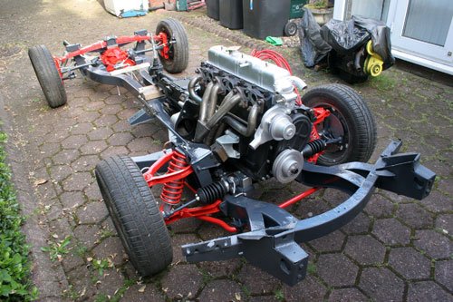
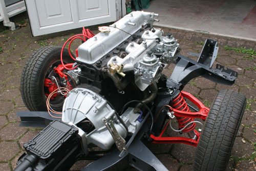
Finally have the chassis back on its wheels with the engine installed
Stainless steel exhaust and manifold fitted.
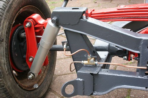
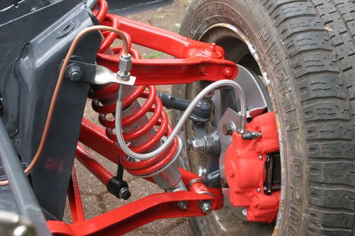
Copper brake pipes made and fitted with stainless braided hoses.
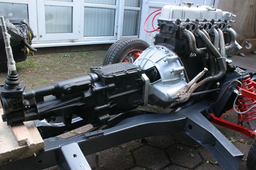
Engine and type 9 gearbox fitted with ally adapter plate between gearbox and bell housing, will make anti vibration mount for the gearbox to complete the job.
Finished the gearbox mount bracket today which means i can now finally fix the engine and gearbox to the chassis at the weekend.
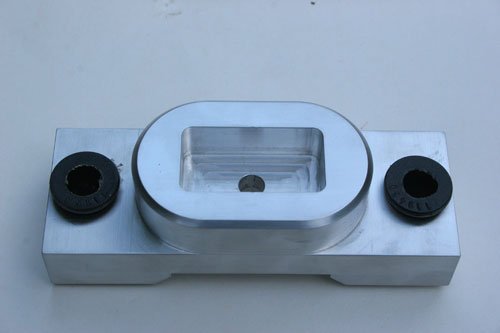
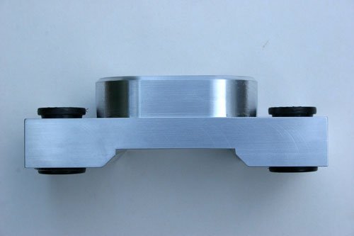
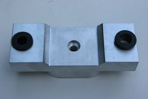
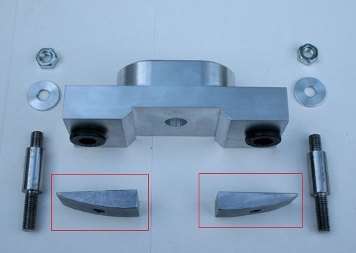
Made out of a solid billet of ally finished size 160mm x 60mm x 50mm. I've over engineered the mount bracket to make sure all is ok. Used four poly bushes left over from the suspension kit which at the moment works a treat, will see how they perform once on the road.
The first image is looking into the well were the type 9 gearbox mount's, the gearbox is firmly attached to the new bracket with a 10mm high tensile cap head with a nyloc nut for safe measure.
First image shows the underside. The second image shows the bits required to add the mount to the chassis. The two wedge shape blocks in the red borders are to be welded onto the chassis where the original well is for the triumph gearbox mount which I've removed, the shape allows the new bracket to sit and mount onto a level surface, i will take a photo once the two wedges are welded to the chassis.
The two bobbins have been machined to a specific length so that the nut and washer will tighten down to the correct height so as to slightly compress the poly bushes into the bracket bore.
once watched the designing of a top notch Italian motor cycle (forgot the name ) on the discovery channel. the seat mounting bracket engineering was a work of art, that no one would ever see, but I suppose if you know it's there and how it was built, this is what makes these machines stand out, and unique. this motor will be a one off top notch quality item. keep up the fantastic work.
Phil 9, Paul L, Gary h, Mister Towed and Thrucroft flyer - Thanks for the compliment lads, its greatly appreciated.
Thrucroft flyer - you are correct, it is how its put together and the fact that i know whats under the skin sort of speak.
Placed an order first thing this morning for a bespoke prop shaft with North West Prop shafts and just had a phone call to say its being dispatched this afternoon for delivery on Monday so that's a turn around of six hours which is exceptional service, i certainly will recommend North west Prop Shafts and also the price was very competitive.
Today i managed to fit the type 9 gear box mount and it went well, all holes etc lined up.
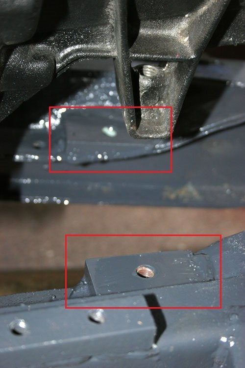
The two pads welded to the chassis circled in red, very near to where the triumph bracket was originally bolted. I pre drilled and tapped M10 holes in the pads and used these as a guide to drill through the chassis after the pads were welded to the chassis.
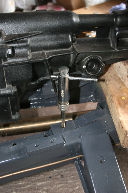
I used a very handy tap wrench with a ratchet mechanism which is ideal for confined spaces as this is. The chassis is now also tapped to M10 so that after the bobbins are screwed in i can put a check nut on the back side to make it 100% secure.
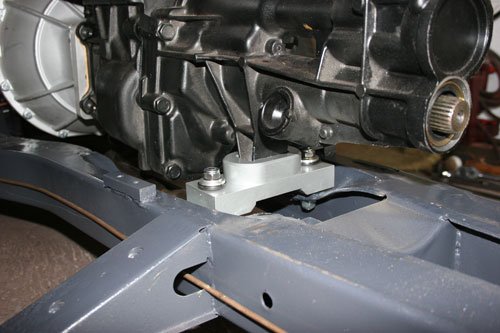
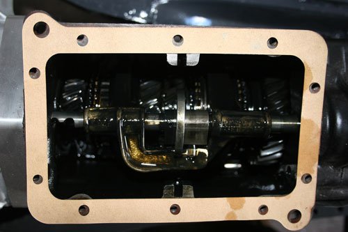
The new mount bracket fitted to the chassis and gear box, it all went very smoothly so i am pleased with the out come. Gear box filled with 1.5 litres of semi synthetic 75/90 oil, 2nd images is looking down inside the gearbox, now need the prop shaft fitted which should be here on Monday.
Another job done and you've probably noticed the brake pipes need securing to the chassis, i am thinking of using plastic P clips spaced every 250mm which should suffice the MOT guy.
Tomorrow i am hoping to rebuild the carbs which were stripped a couple of months ago so that will be interesting trying to figure out what goes where but i did take a few pictures which will come in handy.
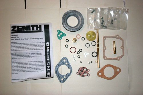
Finally got the Strombergs rebuilt with a full overhaul kit and they are looking good.
Full overhaul kit for one carb, each kit contains all replacement seals, float chamber needle valve, diaphragm, fixed jet, spindle bush/seals, gaskets, spindle (one long and one short spindle), butterfly plus washers and screws. Fairly straight forward rebuild just have to make sure the new fixed jet is positioned just below the bridge, the part the piston rests on at the bottom of its stroke. Also reset the float height to 17mm, invert the carb body so the float rest down on the float chamber valve then measure from the carb body (gasket removed) to the highest point of the float, to adjust the height simple bend the tab that rest against the chamber valve. As the insurance add on the tv says SIMPLESSSSSSSS......
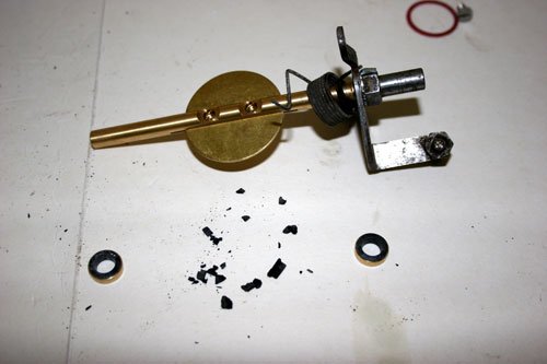
This is what is left of the spindle seal, it looked ok when the spindle was removed but after prodding with a small screw driver the seal crumbled so it definitely was time for an overhaul, these are probably the original 40 years old seals. The new seals in brass housings are either side of the crumbled seal plus new spindle and butterfly trial fitted.
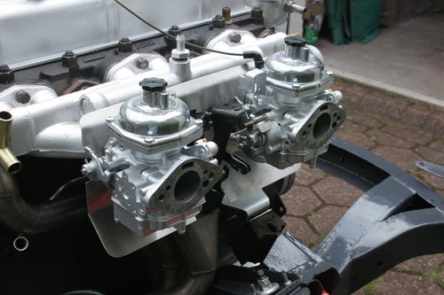
The finished carbs fitted to the engine with the stainless heat shield which i made earlier, had to cut various bits from the shield to accommodate the carbs and their linkage. I've also polished the dash pots which now means i will have to keep polishing them, may of been wiser to have them bead blasted which leaves a clean satin look with out the constant polishing, may be something to do later.
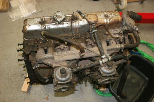
This was how the carbs and engine looked a couple of months ago, its surprising how bad it looked back then.
Finally placed an order for the body a week ago so not long now until i move on to the next stage.
So to fill the time in I've been busy making a few things on the to do list.
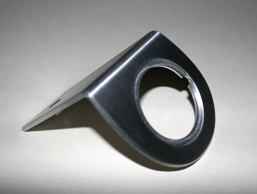
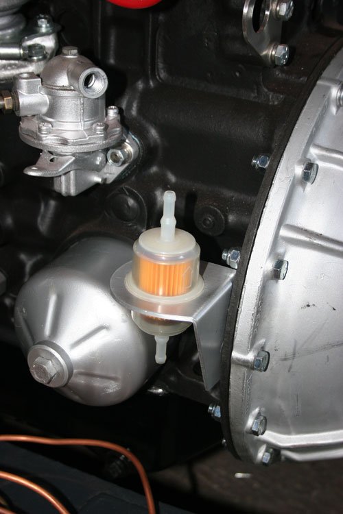
Made a bracket for the fuel filter to sit in out of 2mm ally plate. On hindsight i think that the orientation of the filter may cause issues later on so maybe i will have a rethink on where to position the fuel filter.
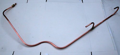
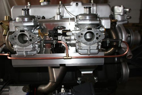
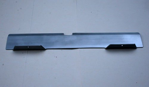
Made a new copper fuel line from the fuel pump to the carbs used the original brass T piece just had to clean it up and re tin. Also made a small heat shield that will act as a point to fix the copper fuel line to, this will prevent the copper pipe from work hardening due to the engine vibration.
A note for anybody who has a GT6 engine is the clutch slave cylinder is the same as that fitted to a landy defender 2.5 but the landy cost's £7 and the replacement from a triumph dealer is £26.
The original cylinder bore was 1'' which is no longer available and has been replaced with a 7/8'' bore, just thought i would post this as its a saving and the triumph dealers are way over with their price.
The steel for the sub frame arrived yesterday so today i am going to fabricate the frame which should be fun, i have a rough sketch off Andy at Ribble HQ which i will use as a guide and adjust as i progress but if any body has any advice feel free to let me know.
A question for those guy's out there who have fiber glass experience - Is there a particular way that steel is bonded to the fiber glass so it becomes part of the fiber glass panel for example the bonnet area.