MadaboutKitcars

This is a read-only archive of the old Madabout Kitcars forum. New posts and replies are no longer possible, but every thread is still here to browse and read.

Another Cordite Is Born ...

30 Jul 2014, 9:05am
Scottie, Oxford & Mr T - Cheers chaps. :cool:

There is a "cunning plan" to provide access to those bolts that isn't 100% finalised yet.

If I quickly bring up this photo from the other day...


Access to the fuel gauge and the fuel line itself will be via a removable panel in the rear cockpit wall.

Access to the bolts and the fuel tank filler hose will be from the rear.

I was actually looking at this yesterday, although I didn't want to mention a half baked plan just yet.

But as you've asked....

I have looked at various boot openings in numerous build threads and think an access panel will be best for me.
( As I will not need to use the boot for most short trips in the car. )

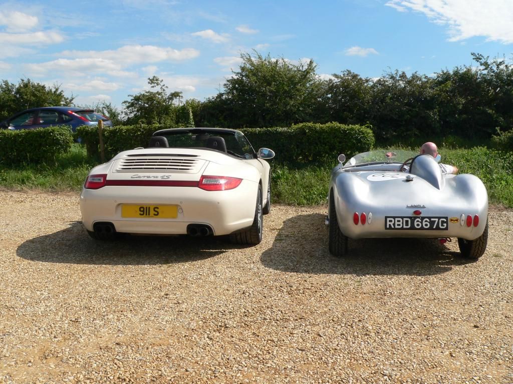
Some sort of cross between Tribute's Kobra...


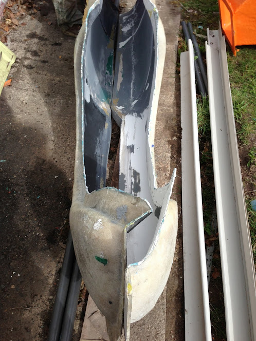
And something like this, that cuts across the twin humps...


Although I am still not sure where I am going to make the various cuts required.

In fact, there is so much work involved I've been trying not to think about it too much at this stage. :rolleyes:

But I do need to do something, so I'll just add it to the "To Do" list.

Right, I'm off to check how my new cockpit lip is getting on.

Cheers, Paul. :)
30 Jul 2014, 7:59pm
Struggling - Part 1:
Today's top tip is build up a cockpit edge the way Mac did, like this.


Whatever you do, don't copy my little bit at a time approach. :rolleyes:

It started off well enough as the work I did yesterday was revealed.


Even the join along the top edge worked well.


So I added some fibreglass filler to the top edge of the "gapping wound" like so.


The new lips even cleared the frame when the body shell was put back on. :cool:


Even without the corners being 100% finalised, there is already much better clearance for the seats on both sides.


Then I started on the next round of lip building and had my first issue with the hump.

As you look at the photo, the body shell on the right of the hump is significantly higher than the body shell on the left of the hump.

So without anything with an edge and a curve to play with I was going to have to do this in stages.


I also roughly sanded down the filler so I could work in this area too.


I forgot to mention yesterday, that unlike Scottie I only have 4 clamps to play with, which is not helping either.

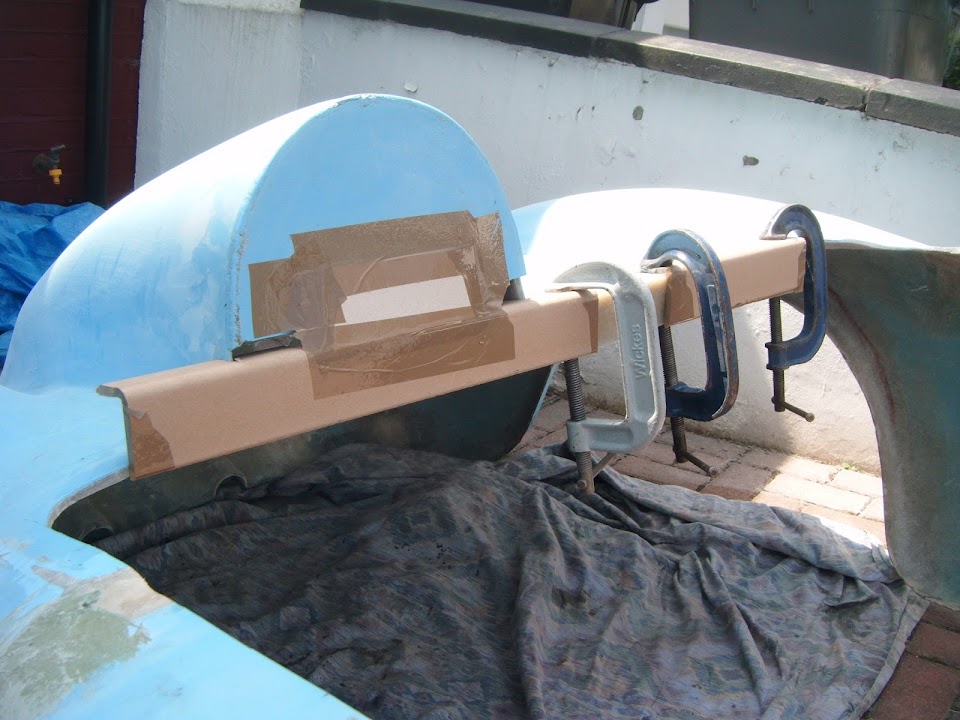
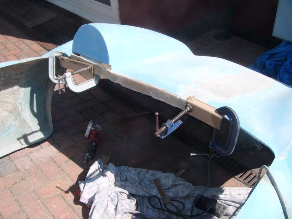
So this was the set up for Round 2.


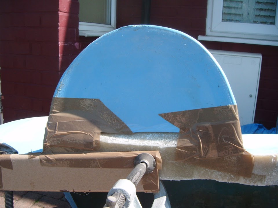
Note:
I needed to 'glass behind the hump in order to support the lip I was building along the bottom.

And this was the view just before the work began.


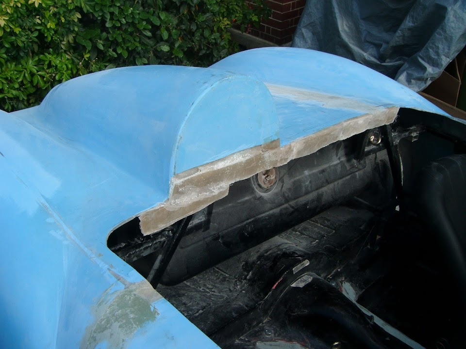
Two sessions and multiple layers of matting later and it looked like this.


I also added a second layer of matting to another part of the driver's side of the body shell.


Between the twin tail pipe recesses.


And behind the corner crack I repaired the other day.


With the formers removed and a light tidy with the grinder it looked like this.


End of Part 1.
30 Jul 2014, 8:00pm
Struggling - Part 2:
Then I set things up for Round 3.


Another two fibre glassing sessions and multiple layers of matting gave me this.


After formers removed & a quick tidy.


Everything was actually looking good until I re-fitted the body shell...

Obviously, there was still a bit of work to do, but the foundations of the rear cockpit lip appeared to be in place.


But all was not well, as I needed to weigh the scuttle down to stop it wobbling all over the place. :icon_sad:


Unfortunately, when I was adding extra fibreglass to re-enforce the new lip, I was also building a clearance problem. :icon_evil:

So I marked up the offending areas on either side of the hump.


In order to save time testing, I did the grinding with the body shell propped up.


Although I needed some "steps" so that I could actually climb over the body. :rolleyes:


After:


The net result of this work was to simply move the problem to a different area. :frusty:

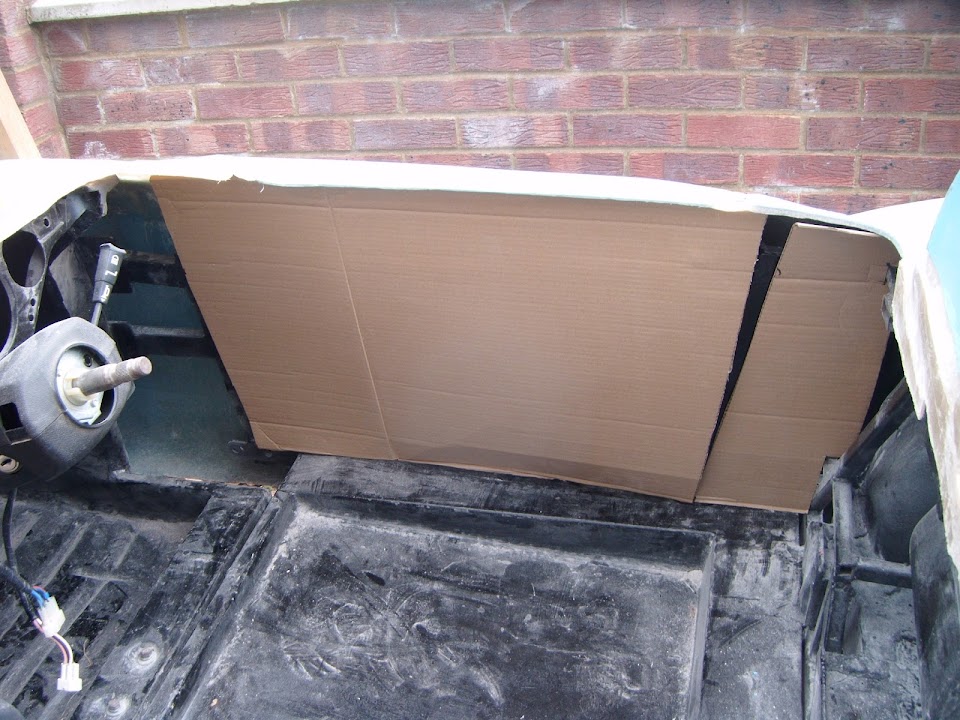
However, I added some cardboard under the centre of the rear cockpit frame work.


This seems to have done the trick, so I will definitely be building the support panel in this area.

However, I might need to re-draw the lines for the Spitfire wheel arches now I know where the body will sit.

So another one of those days where new jobs are added to my list, quicker than I can tick off the ones already there.

Until next time, take care, Paul. :)
30 Jul 2014, 9:59pm
Paul, there is no wrong way or right way, just your way, sure you may do it differently next time but it will still be your way :-)

Keep at it

Mac
1 Aug 2014, 7:40pm
Mac - Cheers. :cool:

- - - - - - - - - - - - - - - - - - - - - - - - - - - - - - -

Making Brunel Proud...
Lots of family stuff going on at the moment, but I did get a chance to do some car work this afternoon.

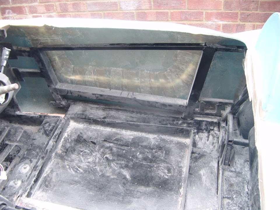
Here is the area where I want to build my support structure.


Note:
The mess is one of the reasons I want to get quite a bit more of the body work done at this stage.
All of the dusty stuff still needs to be removed so I can do the final round of work on the underside.
But it would be a pain trying to keep the "Moon Rover" clean if I had to keep attacking the body shell. :rolleyes:

Anyway, I cut a length of box section and clamped it into place.


It made a nice change to be welding, rather than doing messy fibreglass work.


In true "Belt & Braces" style I wanted to add a couple of cross sections.

They just needed a slight trim due to the angles of the framework.


With those welded it, this is what it looked like.


So the next step was to cut out, clean up & clamp a section of fresh metal over the top.


Again you can see the impact of the angle of the framework here.
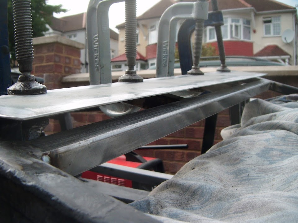


So I simply welded one side first, before clamping the other side down and doing some more welding.


This is as far as I managed to get today.


So I will have to come back and finish the welding another day.

Although, to be honest, it is already rock solid now and it can take some serious weight without flexing. :cool:

Based on Mister Towed's feedback, this is an area where your hand instinctively reaches to lift yourself in & out.

So I'd rather over-engineer a solution, than under support the area.

I even made sure there was enough room for me to rotate the fuel pipe through 180 degrees.


This is on the "To Do" list, I even have a new olive in a box ( somewhere :rolleyes: ) ready for the job.

Thankfully the body shell still fits over this and the scuttle wobble had gone too.

So a big blob of bonding paste, when the time comes, should support the rear bodywork very well.


The rear of the body shell will also get supported in the following places:
- By joining the sides of the body shell to the Spitfire rear wheel arches.
- By joining what is left of the Spitfire boot floor to the back of the body shell.
- I might also add some extra support when I put the boot opening in place.

As I've starting playing around with the cockpit panelling, it is slowly becoming much clearer to me how the body shell becomes "fixed".

Until next time, take care, Paul. :)
8 Aug 2014, 1:13pm
Hi Paul, when you put your boot opening in, if you put in a rain channel, that strengthens things a lot, it did for mine anyway!

Gives the whole boot area rigidity

Good luck with it.
9 Aug 2014, 6:56pm
Scottie - I do plan to build a rain channel for the boot lid / access panel.
I will also be adding some extra cross bracing in that area and to the lid itself.

- - - - - - - - - - - - - - - - - - - - - - - - - - - - - - -

Family Holiday:
Just back from a week away with the family, which explains the lack of progress on the car.

Although I did use some of the time away to work on various car related "To Do" lists.

Obviously, as soon as you write things down, you realise there is still a very long way to go. :rolleyes:

But I do find that these lists are a big help to me when it comes to figuring out the order I need to tackle the work. :cool:

- - - - - - - - - - - - - - - - - - - - - - - - - - - - - - -

DVLA:
Just before we left, I received a reply from the DVLA, following my latest attempt to check the re-body rules.

The bad news is that they didn't answer my bumper bracket questions at all, just sent me forms and a booklet. :icon_sad:

But the good news is that I now have a contact name, so I have also drafted a reply letter while I was away.

However, the really good news is that the V5C changes to go from a Spitfire to a Cordite seem less than for a Herald to a Spyder. :cool:

Based on other builders' experience, these days the "Make" must remain as "Triumph".

I have no problem with that and as I've said before I will probably copy AndyP57's use of the new Triumph Motorcycles logo.

So the only V5C change I need to make is to the "Model", which must change from "Spitfire 1500" to a new name.

I have picked a new name (not Cordite), but want to wait until the paperwork is sorted out before revealing it.

The "Body Type" is already listed as "Sports", so apart from colour, there are no other changes required to my current V5C.

So I will keep you posted if the DVLA provide the clarification I am now seeking in my reply letter. :pray:

- - - - - - - - - - - - - - - - - - - - - - - - - - - - - - -

Looks like tomorrow will be a wash out, so it may be next week before I get back working on the car.

Take care, Paul. :)
9 Aug 2014, 8:03pm
Hi Paul did DVLA mention anything about a visual inspection in the reply or is it a case of sending the forms off and waiting to see what their response is, i did read some were that you have to provide invoices and build diary to back up a re-body case, is this mentioned in the DVLA info.

Which forms and booklet did they send as i will have a look to see if an online copy is available.
10 Aug 2014, 11:19am
DVLA Info:
It seems my last post has generated a bit of interest, so I have just done some digging on the 'net.

This is the stuff I was sent:

DVLA Booklet INF26
http://www.direct.gov.uk/prod_consum_dg/groups/dg_digitalassets/@dg/@en/@motor/documents/digitalasset/dg_180218.pdf

Form V627/1
https://www.gov.uk/government/uploads/system/uploads/attachment_data/file/278783/V627X1_270913.pdf

V894 Reply Slip
Apparently this is not available on line. :icon_sad:

What is not clear to me, is if the "re-body" rules used by previous Sammio builders are still around.

Based on INF26, I think Section 2 (Vehicles that have been rebuilt using a mix of new and/or used parts) applies.

Because Section 5 (Kit conversions) refers to "a kit of new parts" and IVA.

So I am about to check that my build falls under Section 2, as that seems closest to the old "re-body" rules.

In my case, the chassis VIN matches the V5C, so counts as original.

Plus I am re-using the suspension, axles, transmission, steering & engine from my donor.

However, the risks are that the "Kit Conversions" section also mentions "the general appearance of the vehicle will change".

Hopefully this means a significant change in appearance.

E.g. A 4 door, 5 seater Ford Sierra saloon into a 2 door, 2 seater Pilgrim Cobra replica.

As previously mentioned, my Spitfire "Body Type" is listed as "Sports" and I would argue that the general appearance will still be "Sports".

The DVLA did want photos of "before" and "after", including one with the registration number on it.

Plus information on the changes that were carried out, but supporting invoices.

For me, the main invoices required would be:
- Original donor car
- Sammio Cordite kit
- Second hand body shell from Ebay used for my bulkhead & rear arches

Another area I want to check is the application timing as the DVLA talks about the completion of the build.

Whereas, I want to apply for the V5C changes as soon as the body shell is bonded into place, complete with internal panelling.

My argument will be that I need the revised V5C in order to MOT, Tax & insure the car for the road when it is complete.

So I'd rather get the paperwork sorted out in advance, rather than start the process when everything else is done.

Obviously this whole area is a can of worms, so I will see what their next reply says.

Cheers, Paul. :)
10 Aug 2014, 4:30pm
Paul,

I did some reading up on all of this malarky the the other week and we're more than covered by one of the new schemes, i just can't remember which off the top of my head.

I made some notes in work, so i'll dig them up in the week as i'm nearly at the stage where i'm about to sort my V5 out anyway.
10 Aug 2014, 7:22pm
Very thorough and interesting read Paul, hopefully these kits fall into section 2 which looks to be simpler than section 3, i suppose it's down to how the DVLA guy looks at it but will wait and see what happens.
10 Aug 2014, 7:44pm
My experience with the DVLA is KEEP IT SIMPLE and IF THEY DO'NT ASK DO'NT TELL :tape2:.

Fill in the paper work complete with "informative" photos of the build ( Paul L you might need some help on that one :icon_wink:)

I like to have front right quarter and left rear quarter, showing the registration before "work" starts. It is also nice and helpfull to include a photo of the "original" chassis plate, and engine number.
IMHO, I think photo evidence will soon become part of the DVLA form and have to be submitted as part of the form as it is with HGV conversions.

More photos taken from the same angles partly striped, then full striped, then refurbished chassis, then rolling chassis, then cage frame bolted on, then finally body on with registration number in place.
This will show the major components in place which are what DVLA and VOSA are looking for. VOSA score each major component to make a total of 14 points. To retain the original registration the score must be over 8 points and must include the original "unmolested" chassis ie; the chassis engine and steering.
Chassis 5 points.
Axles 2 points.
Suspension 2 points.
Steering 2 points.
Transmitsion 2 points.
Engine 1 point.
Total 14 point
You will note the bodywork scores nothing according to VOSA
Make a point of showing and high-lighting the original components as this is what DVLA and VOSA are looking for. The fact that we use every original "unmolested" components helps big time!!


Also include a brief description of what's happening, remembering the person reading the form and looking at the photos doesn't know what a spanner is and never looks under a bonnet.

If you have no invoices say why you have none ie; recycled every thing from the donor.
NEVER mention any thing is SECOND HAND :tape2:
Paul L , the bulkhead you used was the old one from the original donor wasn't it :icon_wink:

DVLA personal will not take any chances so try and take away the guess work.

Keep it simple.
11 Aug 2014, 9:36am
Dave - Good luck with your application, it will be nice to see how you get on.

Swifty - My reply letter to the DVLA asks for confirmation that Section 2 applies.
From my understanding, we are definitely not Sections 3, 4, 6 or 7.
However, I think it is "Section 5. Kit Conversions" that causes the confusion.
I am NOT adding "a kit of new parts" to an existing vehicle.

My replacement bodyshell is actually made up from the following:
- A selection of new parts from the Cordite kit
- Parts from the original vehicle (petrol tank, filler cap, etc.)
- Old parts from a Spitfire tub (bulkhead & wheel arches)
- New parts from other suppliers (aero screens, rear lighting, etc. )
- Home made parts (brackets, fixings, etc. )
- Modifications to new kit parts (replacement scuttle, sealed doors, widened rear, etc. )

I am sure parts like your home made hand brake panel mean you are not adding a "kit" of parts either.
Similarly, Scottie had not used a kit of parts, but parts from a kit, plus other items.
To me, a "kit of parts" is what you get with a Caterham kit, not what we are building.

Mike - Thanks for the detailed reply, as that ties in with my understanding.
I've always assumed that at least one person in the DVLA probably reads car forums like this one.
Thankfully, the "old" body tub that I used has an Ebay sales record & its own VIN plate. :cool:
Actually, I have tried to keep good records of everything I have bought for this project.

I've included these "sample" photos with my DLVA reply which seem to follow your suggested approach.


Although I only have "work in progress" photos for the replacement bodyshell at the moment.


So I will be very glad when I have finally bonded everything together.

Cheers, Paul. :)
12 Aug 2014, 3:09pm
Well the forecast said it would be dry, so I took a chance to play outside...

Bloody Weather - Part 1:
This is Tribute's new 250 SWB under construction and they do make their "cutting & shutting" work look very easy, .


However, I have a long way to go before I am even half as good as Chris & Dan. :icon_sad:

So I guess I need a bit more practice...


:icon_wink:

Before I started cutting, I needed to ensure the body shell was sitting on straight.

Without a layer of bonding paste front & rear, the shell still wants to "wobble", so I weighed one corner down.


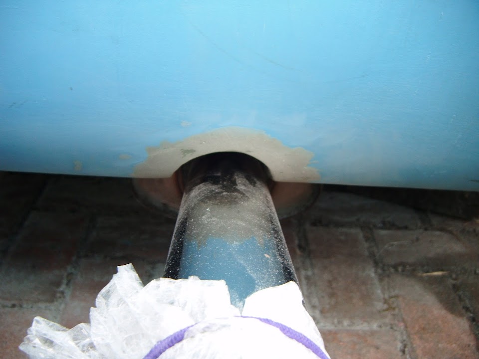
At the rear, the tail pipe exits now act as my point of reference for aligning the body shell.


With the body shell "set", the rear passenger arch still covers the wheel nicely.


But the driver's side doesn't.


This is all related to the issues with the original Cordite buck, which was covered in more detail previously.

Mac did a neat job when he fixed this corner, but I didn't want to touch the area where my boot lid will eventually go.

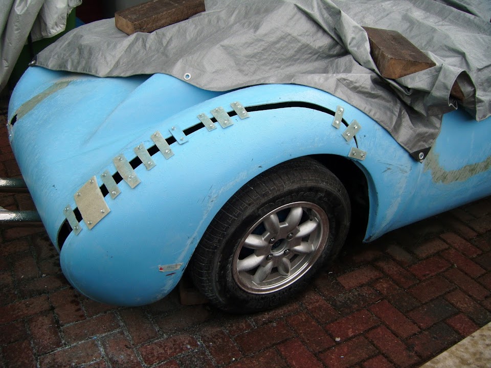
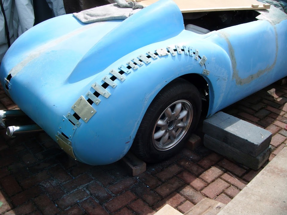
So out came the jigsaw and I cut through a section of the rear arch like so.


I had just put the first tech screw in place when I felt a drop of rain. :icon_evil:

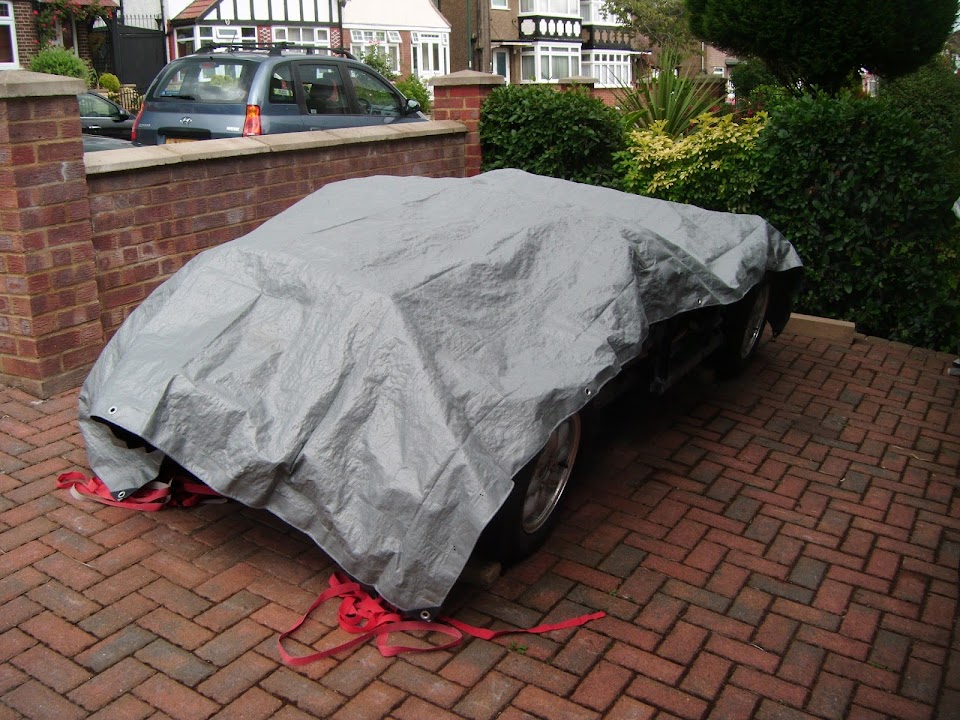
Given the heavy downpours of late, I decided to get a cover over the rest of the car before continuing.


This was a good idea, as, sure enough, before I had finished "stitching" the two sections back together the heavens opened.

This was as far as I had got...


By the time I'd take the photos above, covered up this corner and packed my tools & bits away, I was soaked. :icon_sad:


That is how I left the car and until the sun came back out.

End of Part 1...
12 Aug 2014, 3:11pm
Bloody Weather - Part 2:
Unfortunately, I only managed to add a few more brackets before the rain came hammering down again. :rant:

I must confess to a major sense of humour failure after getting soaked a second time.

But it was third time lucky, by the time I managed to finish the "stitches".


Due to the curves involved, I had to use a lot of smaller brackets this time.

Here is the "after" view to compare with earlier.


And this is the view along the rear of the car, before & after.


Overall, I am pretty happy with how this has turned out.
- Is the new arch perfect? - No.
- Are both arches now completely symmetrical? - No.
- Is the new arch better than it was before? - Yes.

So that will do for now and that should be the last of the major surgery (touch wood).

I just had time to start cutting some templates for the cockpit side panels.


Due to the angles of the framework, I plan to use three panels, rather than one.

With the panel closest to the dash having a "hollow" built in to access the mounting brackets for the side mirrors.

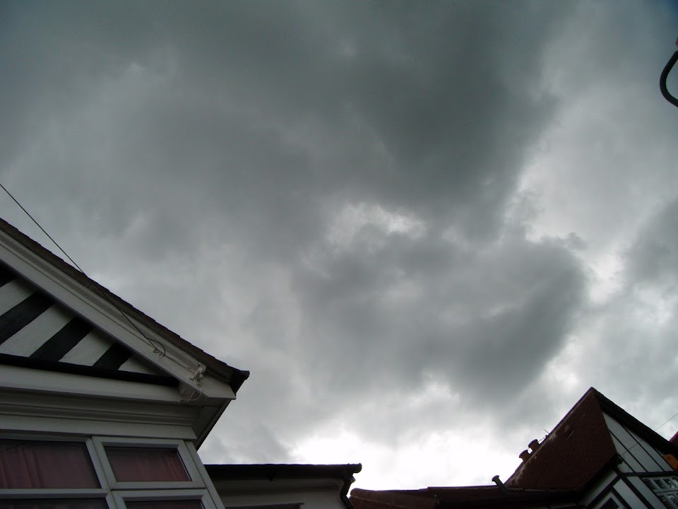
But I didn't get a chance to start mocking this up as the sky looked like this.


So I decided to cut my losses and call it a day, rather than risk a third soaking. :rolleyes:

Anyway, it was good to be back working on the car, regardless of how much I actually got done. :cool:

So until next time, take care, Paul. :)
12 Aug 2014, 3:39pm
Good going, Paul.

I don't know if the back of the Cordite is identical to the Spyder but it does look like it is as I have the same problem of the O/S rear arch drifting inwards and not covering the wheel to the same extent as the N/S.

With the help of my roll hoop frame, I was able to draw a reasonably accurate (ha ha) line down the centre of the car and all the way to the very back. When I measured from the centre line to two "equivalent" points (visually) on each of the rear wings, I was surprised to see that they were within 10mm.

What am I trying to say? Well, it looks like the Cordite solution pursued by you and Mac adds ~50mm to the width of the rear on the O/S. If I were to take this approach it would make my rear-end look odd (ha ha again).

How does the surgery affect the view from the back? Does this new cut just balance out the added width on the N/S? It might be that you now have a well-balanced "wide boy" Cordite.

My feeling is that the built-in asymmetry lies in the vertical plane of the rear wing rather than the horizontal, and that it is the vertical face behind the centre line of the wheel that needs filling-out a little.

If the above makes any sense to anyone else I shall be amazed. It's just that it looks like an awful lot of width to add to the rear body to cover a bit more of the rear of the wheel (the original view from the top wasn't too bad).

This is in no way a criticism, just the ramblings of a mad man who will have to address a similar problem very soon.

Update: I've just looked at Mac's pics and it would appear that he has taken more of a twist approach to get the wheel covered, and has not added as much width. As I said, by adding width to both sides, you have probably achieved a balance. Hey, Oxford, shut it!
12 Aug 2014, 6:06pm
oxford1360 wrote:
...Does this new cut just balance out the added width on the N/S? It might be that you now have a well-balanced "wide boy" Cordite...


Oxford - Funny you should say that, because I thought exactly the same thing earlier today.

I can't get a decent photo of the rear of the car at the moment, as there is a hedge in the way. :rolleyes:

But I will try to remember to take one when I next have the body shell off the frame work.

The problem I have is that Mac is making minor tweaks to the Cordite/Navigator MkII body shell.

So I still have to fix some of the original Cordite MkI problems that his Navigator body shell no longer has.

You might remember just how far Mac moved the rear passenger side on the original Cordite! :eek:


I know I keep coming back to the following photos, but they do help justify the butchery I'm doing.

The original driver and passenger sides of the Cordite buck next to each other.


The rear end of all Spyders seem to have a nice sweep on both sides, as per Mr T.


Whereas, I had a nice sweep on the driver's side and a much "flatter" profile on the passenger side. :frusty:

But the rear passenger side also had the problem of the wheel arch not covering the tyre.

This was AndyP57's original Cordite demonstrator.


So I fixed that problem by cutting the rear of the car in half and pulling it out a bit.

But that still left me with two different rear "sweep" profiles.
( Well, until today that is. :icon_wink: )

Widening part of the body shell arch, rather than just moving the whole arch has also helped.

As the width of the driver's side rear arch was less than the passenger side one. :rolleyes:

So I believe that I have made an improvement, even if I haven't got a perfect match on each side.

Cheers, Paul. :)

PS
Feel free to "ramble" any time and I look forward to seeing your body shell work.
12 Aug 2014, 6:55pm
Ah, I'd forgotten that Mac was on a MkII. And, yes, mine is the same as T's, and has a rather nice sweep to it.

Foolishly I had assumed that a Spyder and a Cordite Mk I had the same back end. As if!
13 Aug 2014, 5:54pm
Oxford - No, I was the foolish one for believing the Cordite was an improvement on the Spyder and an easier build. :rolleyes:

- - - - - - - - - - - - - - - - - - - - - - - - - - - - - - -

A start...
Only had a small chance to work on the day today, but did want to start repairing the latest gash.

However, before I moved the body shell I went back to the previous gaping wound.

There are just two small sections left to do.


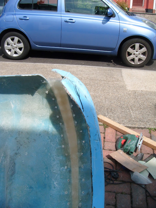
So I removed the bracket and tidied up the edges of the fibreglass.


Then I recycled a section from the "former" I'd used on the spare hump.


Looking at this, it dawned on me, that it would have been a better idea to use hardboard under the brackets.

Having hardboard behind the "wound" held in place by the brackets would certainly make filling in the gaps a lot easier to do.

My wife helped me move the body shell so I could work on it.

Here is a photo of the rear and although it doesn't look like it, the widened arch is very close to the size of the uncut one.


By the time I add the second hump, there will be unmatched curves all over the place, so this will just have to do.

At least it will look a bit better when I trim the edge of the driver's side (right of photo) to match(ish) the passenger side.


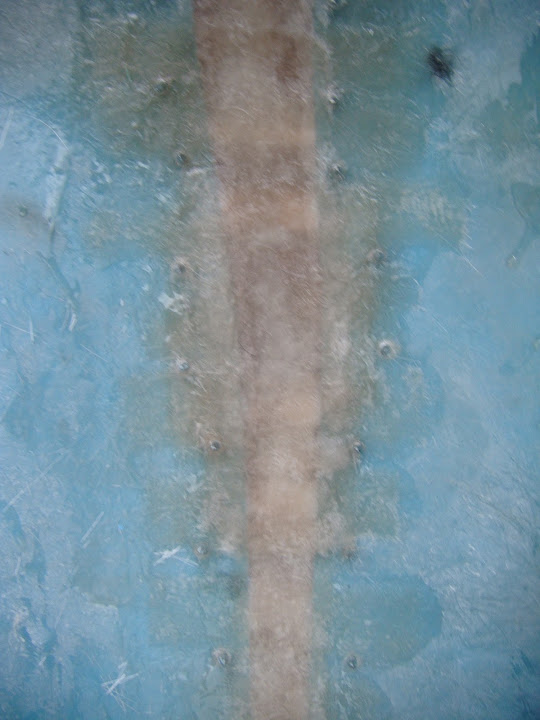
I layered on some parcel tape into the gap.


And after cutting out a lot of matting strips I was ready to start.


But Sod's Law meant the sky now looked like this.


So as a precaution I covered the rest of the car & grabbed a tarpaulin to protect the body shell.


The last section of the gaping would was finally sealed.


I will finish this off when the former has been removed.

I also managed to get most of the latest gash joined up as well.


I did get a little wet and had to work under the tarpaulin briefly, but thankfully it was a very short shower.

Still, I wrapped up my work to give it a better chance of setting if the rain returned.


Right, I'm off down the pub to meet my mate, the one who taught me to weld. :cool:

So until next time, take care, Paul. :)
13 Aug 2014, 6:04pm
Paul L wrote:
Oxford - No, I was the foolish one for believing the Cordite was an improvement on the Spyder and an easier build. :rolleyes:

- - - - - - - - - - - - - - - - - - - - - - - - - - - - - - -


Improvement on the Spyder? How was Gary supposed to improve on perfection? :hail:
13 Aug 2014, 8:30pm
I thought that was a picture of you under the tarp...
14 Aug 2014, 6:11am
Hi Paul

So many screws....! I was wondering if you are using self-drilling screws? It could save you time before you get soaked the next time ;-)

Well, I couldn't really guess from the picture, may be you are using them...

Anyway, good progress!
14 Aug 2014, 8:28am
That is going to be a very special car when its done Paul, you have put so much into it.
It will look fabulous!
14 Aug 2014, 12:25pm
Hi Paul

Having chopped my body around quite a bit. wont the hump over the rear wheel be wider than the other it may look odd!. The best thing I did was move the divers hump to line up with the seat.
14 Aug 2014, 3:11pm
Mr T - Well it was the beautiful Spyder #66 that got me into this mess in the first place! :rolleyes:

Gary - My attempt to finish the fibre glassing under the 'tarp would have made a much better picture. :icon_wink:

Axel - They are self tapping screws, but I still drill separate pilot holes to avoid cracking the body shell which takes extra time. :icon_sad:

Scottie - Cheers, although at this point in the build, I will settle for looking "finished" or "on the road", rather than fabulous. :icon_wink:

CarNoob - I know it sounds odd, but the "cut & shut" has actually improved the symmetry in sections of the humps (see below).
It is not easy to see in the photo, but the rear passenger side of the body shell is also slightly lower than the driver's side.
( This is something I remember Oxford fixing on his build. )
So, as I said before, by the time I add the spare hump, the "ups & downs" across the whole of the rear may well look very "odd". :eek:
But if I ever want to finish the car, I just have to pick the big battles and let a lot of other things just go.

- - - - - - - - - - - - - - - - - - - - - - - - - - - - - - -

Every day has its cloud - Part 1
I started the day by taking a tape measure to the inside of the wheel arches.
( So it was spooky to see CarNoob's question later on. )

At this point the width of the two arches arches is very similar.

Passenger side - Original


Driver's Side - Stretched


Although I must confess it isn't a close match across the whole arch, but "it is what it is".

First job was to remove the brackets and hardboard to leave...

The original gaping wound.


And the latest gash.


Sad as it sounds, I'm still getting a kick out the fact the fibreglass repairs holds everything together.

The next job was to minimise the impact of the different rear arch "sweeps".

As this is what the passenger side looked like.


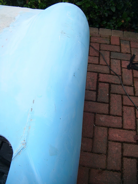
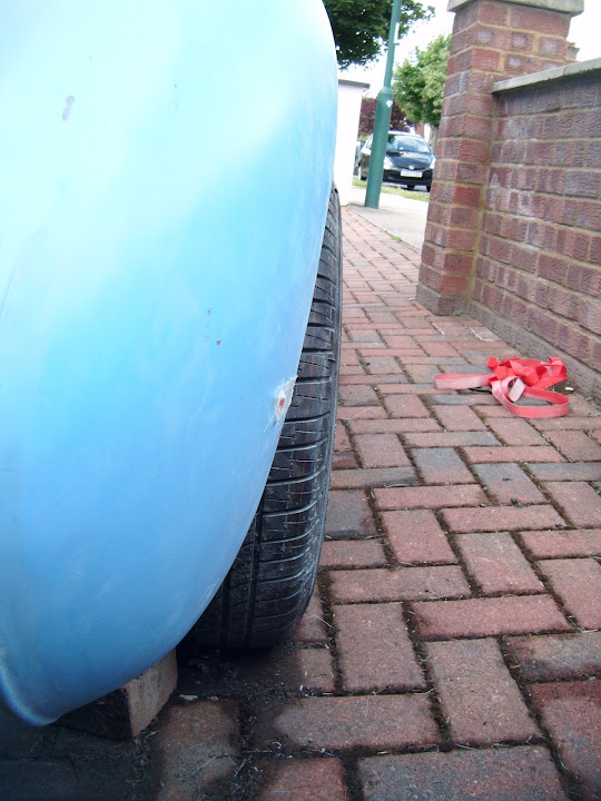
But the driver's side was "sticking up" too much following the cut & shut.


The view along the inside edge also helps highlight the difference.


So the passenger side got a very light trim.


But I cut a much bigger chunk out of the driver's side.


Note:
You can see I needed to cut "down" quite a bit, so I could extend the same body shell profile from the left (as you look at the photo).

End of Part 1...