This is a read-only archive of the old Madabout Kitcars forum. New posts and replies are no longer possible, but every thread is still here to browse and read.
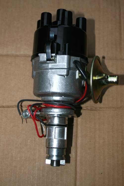
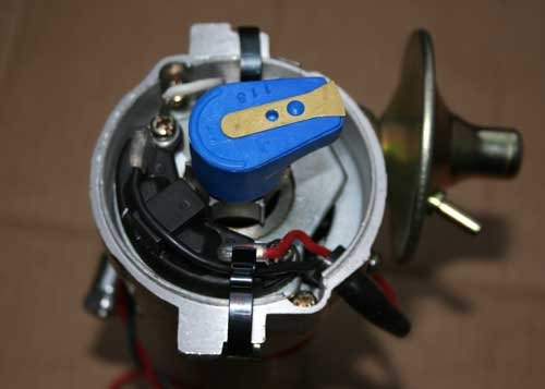
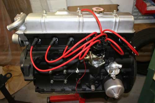
Today the electronic distributor arrived and all looks ok, fitted to the engine to make sure it fits correctly etc.
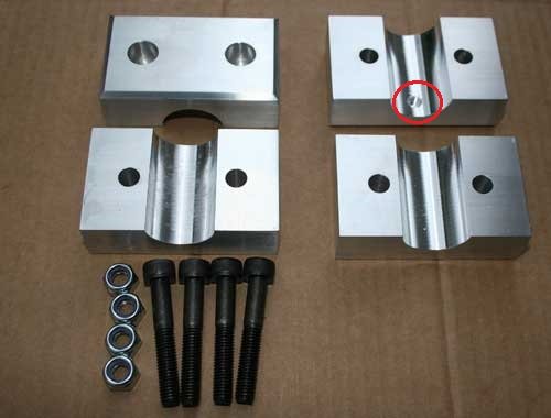
Also managed to finish the steering rack solid mounts made from ally, they are slightly heavier than the ones you can buy online, i think they should be ok in relation to clearance for the engine but if not i can always machine to size.
The red circle indicates were the 3.6mm dia x 2mm blind hole is for the nylon locating peg in the steering rack, only one bracket requires this, the other end of the steering rack has a knurled ring around the tube which grips the bracket surface.
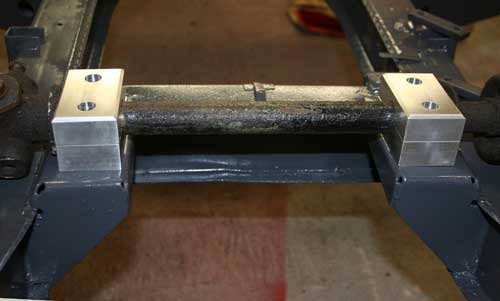
Trial fitted to the chassis with the steering rack (before it has an overhaul) and it looks spot on, measured the sump and i have about 15mm clearance on the sides.
Well that's it for now, i have a few more bits to make, see you all soon.
Not a great deal of progress made today, gave the whole chassis its final coat of paint along with a few other parts while i wait for the poly bushes etc to arrive so i can begin assembling the running gear.
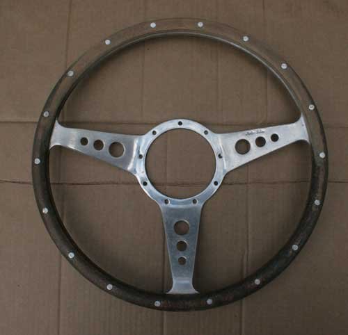
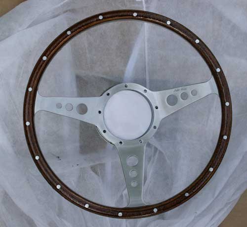
Acquired a steering wheel off flebay which was in need of a little bit of TLC also bought an old steering wheel hub hopefully should be with me early next week then i will look at removing the black finish to a polished ally look.
The before and after pictures of the steering wheel, the ally was badly pitted, rivets were proud of the wood and the wood rim was very grubby. A little bit of sanding and polishing then a few coats of lacquer which brought the wood grain out and gave the look i was after.
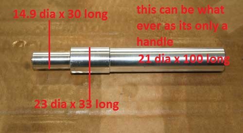
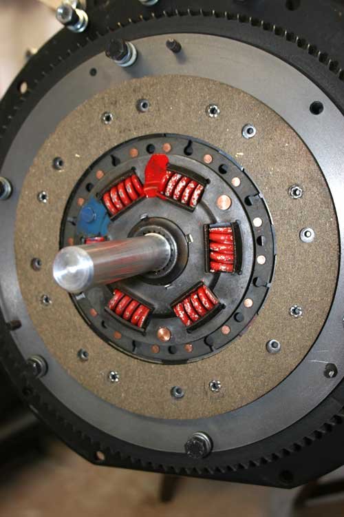
Made a simple aligning tool out of ally to align the clutch friction plate for a type 9 gear box, the second image shows where the tool goes before the pressure plate is fitted to the fly wheel.
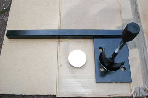
Had a major day in the garden as it was long overdue but still manged to squeeze a few jobs in. Set the static timing of the electronic distributor and made a hub puller which I'll use to replace the rear hub bearings, hope it works, i used a high tensile 12mm bolt, bored out a piece of stock mild steel bar and welded to a 20mm thick plate with a steady bar attached.
New silicone leads fitted, firing order 1-5-3-6-2-4.
Home made hub puller with ally pressure disc to go between the hub stub shaft and puller jacking bolt.
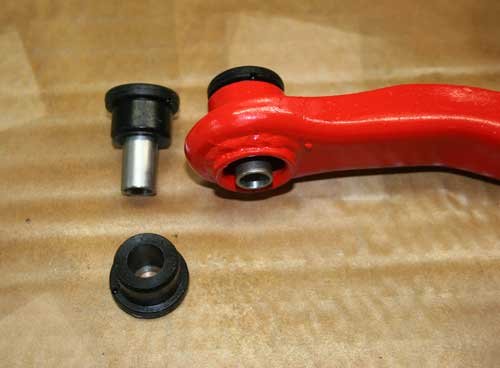
Been away in holiday so had a few weeks away from the build. The poly bushes arrived which are 80 shore comparable to the standard rubber bushes.
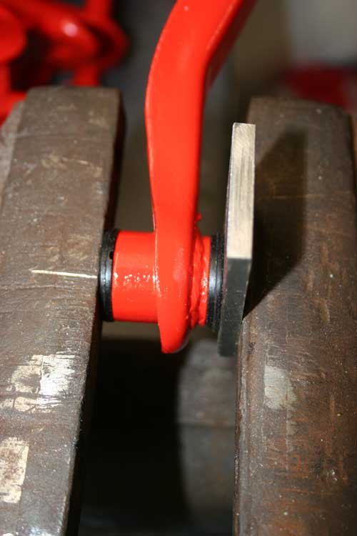
First pushed one half of the poly bush with the spacer tube into the bore.
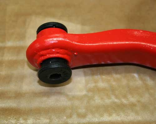
Pushed the second half in as far as possible.
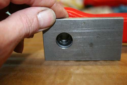
Used a plate drilled out slightly larger than the spacer tube O/D then press home the bush using a vice. The hole in the plate allows the metal tube to be correctly spaced with in the poly bush.
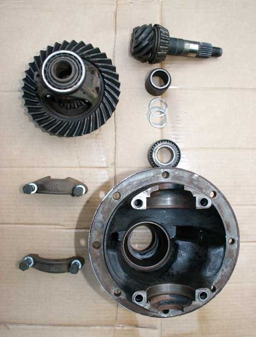
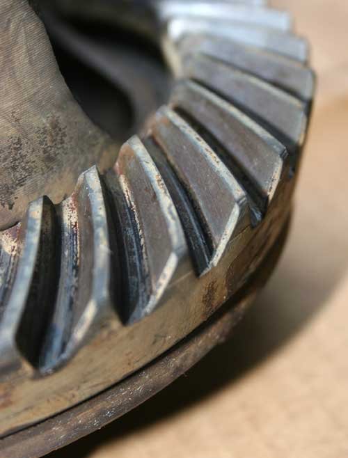
Diff stripped and de greased, the crown and pinion gear have no noticeable wear.
Parts laid out ready for rebuild minus one half of the casing.
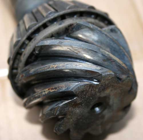
Close up shot of the crown and pinon gear showing no wear at all, just as good as the day it left the factory. Checked the backlash after re assembly using a dial gauge, the tolerance is between 3 to 6 thou, this one is 4 thou so well in spec.
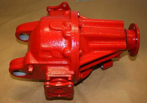
Diff re assembled with new bearings, lip seals and gasket then painted, just need to fit rear two bushes and its ready to go.
Just about finished the steering wheel and boss, waiting for the center badge so hopefully will have pics on hear soon.
Christinedmc - It started off as a quick build but as i go on i keep thinking while i have this part off i'll just check it and it goes on and on.
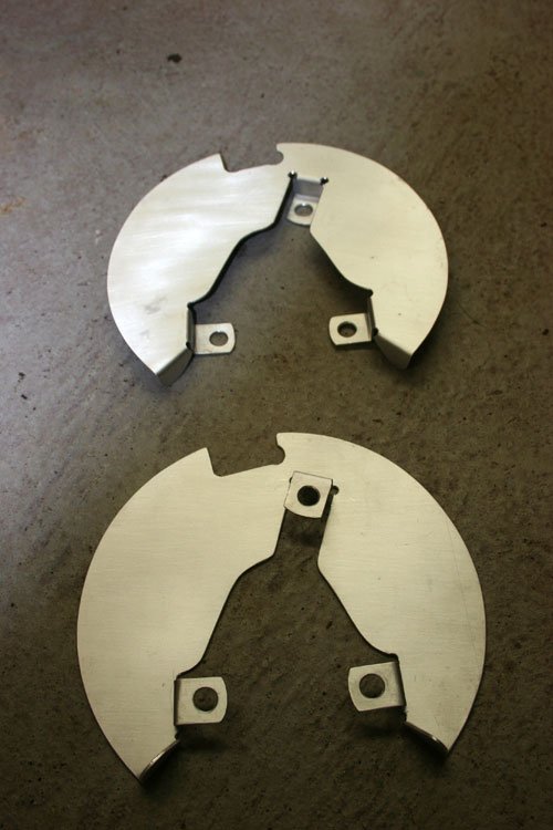
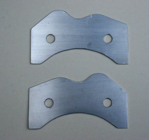
Made two disc shields out of ally (light weight) as the original steel ones are past their best. I used the original as a template after flattening the three bolt lugs down to make it easier to draw around, they are a mirror image of each other so you can flip the template over, just remember to bend the lugs in opposite directions.
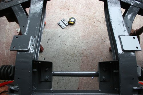
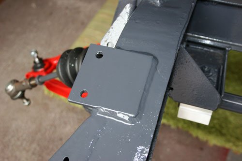
After reading Mr T's thread on his ARB mounting's i thought it best to check mine more closely while the build is at the stage it is and to my surprise both mounting plates had small fracture cracks, it must be a weak point. Fabricated two new plates from 6mm mild steel 80mm x 80mm with two 8 mm holes @ 51mm centers in each plate then welded into place after lining up and checking a couple of times. The images are taken with the chassis upside down, it was easier to work on the chassis this way. One of the old AR brackets in on the floor in the background beside the tape measure in the first image, look closely and you can see the fracture.
Starting to rebuild the chassis to the rolling stage then hopefully mount the engine to be able to measure and fabricate the type 9 gearbox mounting to suit the triumph chassis, I'll then be able to start the engine for the first time since the rebuild and hopefully all will be ok.
Made the final two front disc dust shields out of 2mm ally plate, very easy to work with and light weight.
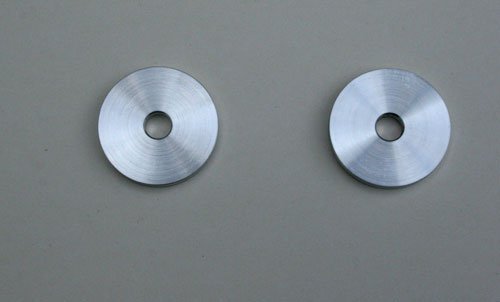
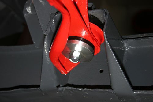
Made two large washers out of ally which hold the differential banjo bracket onto the chassis, the second image shows were, looking upwards, the banjo bracket is the red colour item.
The dimensions are 46mm x 6mm with a 10mm hole.
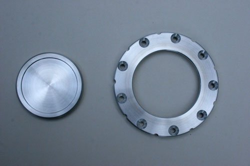
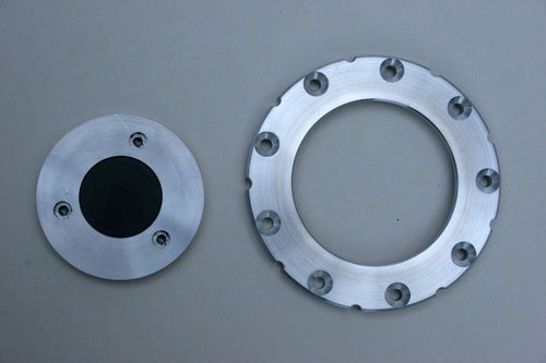
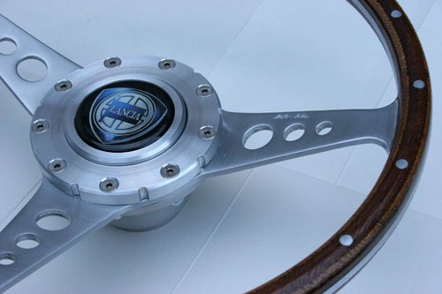
Today i finished machining the steering wheel, made a new center clamp ring and horn push as well as machining the black coating off the boss to match the rest of the ally.
These are the two parts machined from stock ally bar, the horn center push had to be insulated from the rest of the steering wheel to prevent the horn circuit from shortening out, the second image shows the push button upside down with a black nylon disc in the center along with three M3 tapped holes, the slight machined well in the first image is where the badge goes. The clamp ring has a small detail machined around the outer edge to give it a little bit extra with nine matching PCD holes to the original boss.
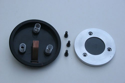
I used the original back cap from the boss but modified it slightly by adding three springs and cap head bolts used to attach the horn push button to the boss with the springs helping to give a smooth return.
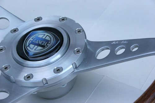
Finished steering wheel with the center badge in place, not sure if this will be the final badge i use, may be more research required.
Today i changed the hardy splicer UJ bearings in both drive shafts which should of been quick and simple task but it did not go as easy as i thought it would.
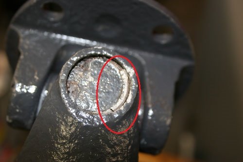
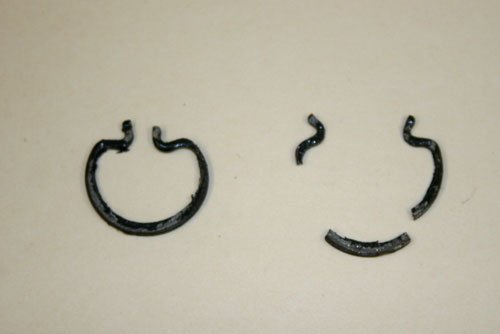
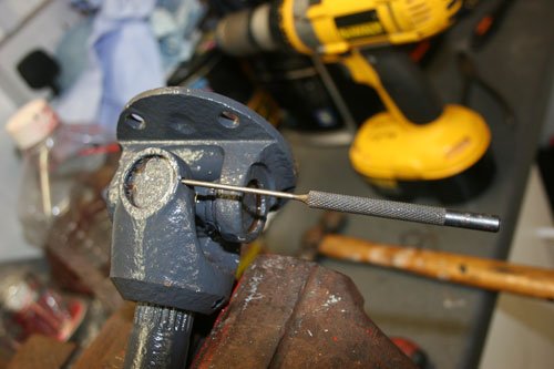
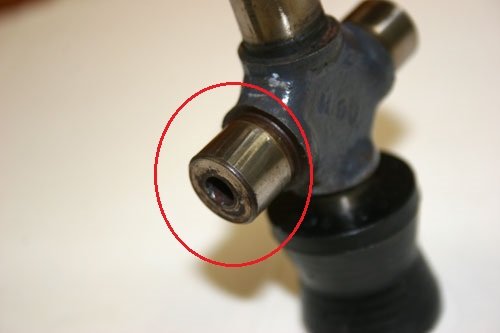
After removing the retainer clips with a pair of circlip pliers two of them smashed. It looked like 40 years worth of the British climate had done its magic. The first image shows the piece of clip still in its groove. The second image shows one of the broken clips.
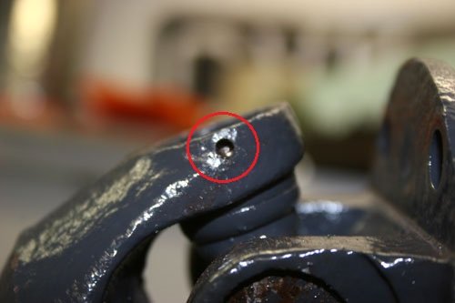
So i had to come up with a way of removing the broken piece which was rusted into the clip groove, i decide to drill a small hole through to the clip and use a pin punch to dislodge the broken clip, which worked a treat.
This image shows the wear on one of the bearing surfaces plus the bearing was bone dry when i removed it, there was play in the UJ which could be felt by rocking the joint on its axis.
Next job is to change the seals in the brake calipers. See you all soon.
Been away so only made a small amount of progress since the last post.
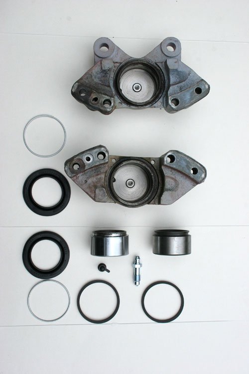
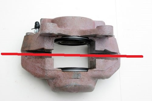
Brake caliper stripped ready for reassembly with new seals etc, had to replace one piston as it wouldn't come out of the bore, Had to weld a bar onto the piston and pulled it out that way. A good tip if the caliper is off the car as mine was is to use a grease gun with a grease nipple screwed into the caliper where the flexi hose screws in and place a bar between the two pistons (red line in second image shows where bar goes) so that when one piston jacks out it hits the bar and transfers all the pressure onto the piston still in its bore.
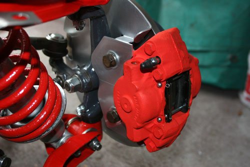
Caliper's re-assembled with new pads etc and painted with heat resistant paint. The second image shows the dust shields made earlier which i have coated in a layer of laquer for good measure.
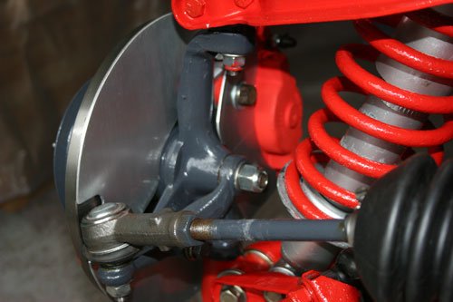
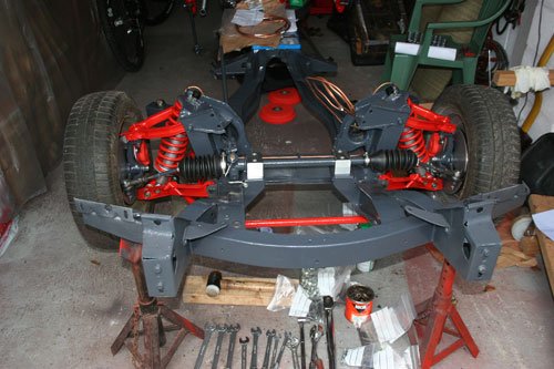
Another major step is achieved by fitting the temp front wheels, only have to finish the rear axle and then its a rolling chassis, its then time to fit the engine and type 9 gear box so i can work out how to fabricate a new gear box mount. Not sure if i will use the ford mount or go along the lines that triumph used on the spitfire with two rubber bobbin mounts angled in towards the drive axis point, after talking to mate who works in Jaguar design apparently this is the better way to have the mount load points pointing in the drive axis center.
All the the builds seem to be an improvement on the last, guess that's evolution for you. And some very talented people with access to the right tools.
Hi Garyh The dust covers were not too difficult to fit they simple stretched over the part of the slave cylinder that's outside of the back plate and tucked under the two spring retainer plates that retain the slave cylinder.