This is a read-only archive of the old Madabout Kitcars forum. New posts and replies are no longer possible, but every thread is still here to browse and read.
I posted recently elsewhere about noisy tappets, which I had after my engine rebuild last summer. My tame mechanic suggested I put some Wynns Valve and Tappet treatment in the oil. within seconds of pouring it in then noise went from sounding like a machine gun to a gentle tick-tick-tick, and that disapperaed after a few minutes.
These tame mechanics obviously know a thing or two!
Chris Cussen wrote:
I posted recently elsewhere about noisy tappets, which I had after my engine rebuild last summer. My tame mechanic suggested I put some Wynns Valve and Tappet treatment in the oil. within seconds of pouring it in then noise went from sounding like a machine gun to a gentle tick-tick-tick, and that disapperaed after a few minutes.
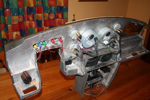
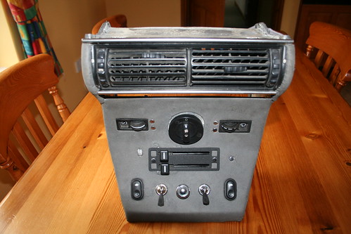
...............I have to say I am chuffed with the way it has finally turned out.
(well there is a little more to do, as the icons are for temporary show, and need the correct ones in the correct place, before gluing in posistion)
There are issues with IVA as it is, and I have a plywood template to place over the instrument bezels, and will remove the flick switches. If anything else does not meet with approval, I'll end up fitting black vinyl wing piping along the offending edge.
I have beefed up the strength of the dash with triangulated supports welded in - despite being screwed to the plywood dash there was not a lot of strength in the centre to resist the Start button being pressed.I have now scewed the dash to the console as well, and the whole structure is much less flexible.
These are shots of the dash and console covered in a dense foam, giving it soft edges and a nice tactile feel.
I have started to fit the electrics in to my car, which most of you will know, I am not looking forward to.Front light loom fitting and connection all went ok.
Next job was to wire in the electric fan. I had included a spare union/socket in my radiator to allow me to fit a standard Sierra radiator fan sensor switch. As a temporary measure I had fitted an old sensor just to bung the hole up. When I came to remove it , it would not budge -so a bit more brute force was applied.........and you've guessed it - the nut has split away from the thin walled tank, and I now have a puddle on my garage floor.
It has just taken me three hours to remove all the electrics to the light bar (thatI had spent all morning fitting), then the light bar itself, along with the nose cone, and finally extract the radiator. Plus another hour to clean the brass tank around the socket nut, ready for it to be re-solder tomorrow.
Harumph - not a happy bunny!!!
On the brighter side my friendly welder has welded together all my bits for the Berlinetta and Roadster light bars which I have made for some of the other MOC members.
If anyone needs any stainless parts - let me know, and I will see what I can arrange? - all at non commercial rates!
Mike
I think we've all had moments like that during our builds, but you'll forget them once your finished!
I'm sure you'll have it all back together in no time at all......
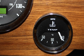
The Smiths Classic Water Temp gauge I chose is not compatible with the BMW VDO sender in the cylinder head. Caerbont (the manufacturer of Smiths gauges) advised I would have to use one of their senders for it to register correctly. I bought one, and after spending several hours adapting it to fit into my cylinder head, I decided to test its callibration.
According to Caerbont, water now boils at 135 degrees C!
............and it is consistently out across the scale.
True 90 reads 125deg C
true 80 reads 110
true 70 reads 85
true 60 reads 75
below that it is not worth using the gauge (......or at any temp based on above!!!)
Do any of you auto electrician bods have any suggestions?
The Smiths Classic Water Temp gauge I chose is not compatible with the BMW VDO sender in the cylinder head. Caerbont (the manufacturer of Smiths gauges) advised I would have to use one of their senders for it to register correctly. I bought one, and after spending several hours adapting it to fit into my cylinder head, I decided to test its callibration.
According to Caerbont, water now boils at 135 degrees C!
............and it is consistently out across the scale.
True 90 reads 125deg C
true 80 reads 110
true 70 reads 85
true 60 reads 75
below that it is not worth using the gauge (......or at any temp based on above!!!)
Do any of you auto electrician bods have any suggestions?
Hi Mike,
I'm not very familiar with these gauges but a quick Google seems to suggest they need a voltage stabiliser to provide a 10 volt supply.
Although I was aware it needed a voltage stabiliser, I did not appreciate it needed to be 10 volts. That will explain the over reading when I tested it direct from the battery.
Trouble was, when tested through the stabiliser I could not get any reading.
I've now checked the stabiliser and it does not work, so I'll order a solid state one from RS instead of the mickey mouse one Smiths supply which even has to be physically mounted vertically otherwise it does not work in its normal state!
Although I was aware it needed a voltage stabiliser, I did not appreciate it needed to be 10 volts. That will explain the over reading when I tested it direct from the battery.
Trouble was, when tested through the stabiliser I could not get any reading.
I've now checked the stabiliser and it does not work, so I'll order a solid state one from RS instead of the mickey mouse one Smiths supply which even has to be physically mounted vertically otherwise it does not work in its normal state!
Hi Mike,
it was just a hunch. I hope it works better with the 10 volt supply.
Certainly an interesting voltage stabiliser that relies on gravity.
I think a solid state one that can supply all your instruments that need 10 volts is a nice idea, but it might be cheaper and quicker to get a new Smith's one. If you buy that RS component you will need to solder it on a piece of 'vero' board and add two bypass capacitors. Then mount it in a small box with some connectors to make it robust for a car environment.
Not impossible but I would just order a Smith's one from Merlin Motor sport.
Hi Mike,
it was just a hunch. I hope it works better with the 10 volt supply.
Certainly an interesting voltage stabiliser that relies on gravity.
I think a solid state one that can supply all your instruments that need 10 volts is a nice idea, but it might be cheaper and quicker to get a new Smith's one. If you buy that RS component you will need to solder it on a piece of 'vero' board and add two bypass capacitors. Then mount it in a small box with some connectors to make it robust for a car environment.
Not impossible but I would just order a Smith's one from Merlin Motor sport.
I was planning to connect it direct - why does it need two bypass capacitors?
There is an interesting article from the MG forum:
A quick look at your numbers shows an interesting ratio
Actual Reading ratio
90 125 1.39
80 110 1.38
70 85 1.21
60 75 1.25
Its not linear but up beyond 80+ it seems fairly consistent.
The temp gauge works onmeasuring the current flowing through the sensor, so to have it over-read there is too much current. You could reduce it by putting a resistor in-line with the wire to the sensor. What you will need to know is the resistance of the sensor at, say 90 to do the calculation.
If you use a multimeter to measure the resistance (R) then the in-line resistor would need to be 0.38*R
That's pretty neat solution!
My comment about bypass capacitors was based on the application note with the component you picked.
Note number 3 in the application notes.
Does anyone know the current taken by a Water temp sender/gauge and a fuel sender/gauge?
Looking on RS Components site there are a number of 10v chips, with varying current capabilities.
Is the one I've identified below likely to be suitable?
Jeepers Peter - you read the detail! Given my application, will this chip work in the set up described in the British V8 forum without the capacitors ?
It seems such a simple fix it it will work reliably?
Does anyone know the current taken by a Water temp sender/gauge and a fuel sender/gauge?
Looking on RS Components site there are a number of 10v chips, with varying current capabilities.
Is the one I've identified below likely to be suitable?
Jeepers Peter - you read the detail! Given my application, will this chip work in the set up described in the British V8 forum without the capacitors ?
It seems such a simple fix it it will work reliably?
Without more knowledge of these gauges it's pretty much impossible to answer these questions although reliability will probably depend more on how well you build it!
Did the gauges come with any kind of datasheets?
You will certainly need a voltage stabiliser if the instrument is designed to work that way. The theoretical 12v that comes from your car's electrical system is not actually 12v anyway, and also not particularly stable.
Using an electronic regulator may or may not work well - although a linear one is better than something fancier (digital). Car electrical systems are full of noise which plays havoc with anything electronic.
Personally I would try to stick with stuff specifically designed for the job. I would use the smiths regulator - even if you have to fix it the right way up!
I have wasted most of the wekend playing about with electrical things I do not understand! - although I have learned a great deal - "receivers - base - emitters"!
I bought a 10v LDO chip from maplins for 99p - well I bought three.
After messing around we got 9.88v out of it. Then I blew it up - quite literally the whole thing blew it self apart! We then got 10.4 vaults when aa 22k ohm resistor was included
At this point I decide to pull the Smiths regulator apart, and to my surprise it is solid state, with a chip, and its own non oscillating resistors.....................
................so, tomorrow, I shall do exactly as you suggest and buy another Smiths solid state regulator, which will cost £15 including p+p!
Out of interest, why would it need to be physically installed vertically - or is this just a sop to the old days when it would have been a bi-metallic strip?
MartinClan wrote:
Just my 5 penneth.....
You will certainly need a voltage stabiliser if the instrument is designed to work that way. The theoretical 12v that comes from your car's electrical system is not actually 12v anyway, and also not particularly stable.
Using an electronic regulator may or may not work well - although a linear one is better than something fancier (digital). Car electrical systems are full of noise which plays havoc with anything electronic.
Personally I would try to stick with stuff specifically designed for the job. I would use the smiths regulator - even if you have to fix it the right way up!