MadaboutKitcars

This is a read-only archive of the old Madabout Kitcars forum. New posts and replies are no longer possible, but every thread is still here to browse and read.

Another Cordite Is Born ...

15 Mar 2014, 8:50pm
Heater Valve Switch...
I spent a long time convincing myself that I must be doing something wrong, or just missing something completely. :mmph:

The cable operation is set up in such a way that the back of the switch & the switch itself can only be fitting one way.


This means the "hottest" & "coolest" settings are actually a "given".

So this is the end of cable position for hot:


And then the cable is withdrawn to reach the cold setting:
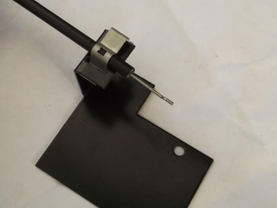


So far, so good.

But the problems started when I tried to find a lever position on the valve which worked in this direction.

I even took the lever off to see if it could be adjusted, but it was also "fixed".
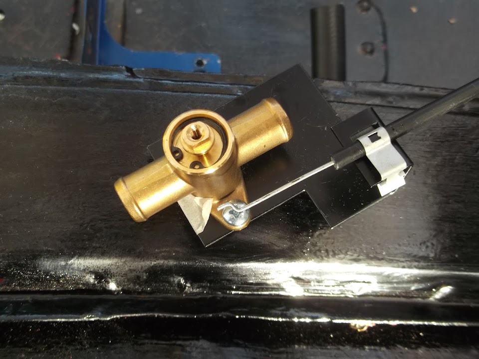


In the end, the only way the lever could be make to push/pull in the correct way was if it was on the "wrong" side of the mounting bracket.


In this position, the value will open/close as it is supposed to.

Now I am happy to admit that I may have been making a simple school boy error all along.

But I couldn't believe how long I'd spend messing about trying to resolve this.

So I decided that I would take my anger out on the offending bracket and hit it repeatedly with a hammer.

It wasn't a very neat job, but I did manage to reverse / turn the cable fixing point through 90 degree.
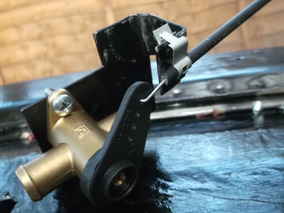


The position above is "closed".


And turning the heater switch "up" now came me this.


As you can see, that wasn't quite right, so I adjusted the cable fixing a bit until this was how fully "on" looked.


By now I realised that I have to turn the dial through the thick end of 300 degrees to go from off to on.

OFF:
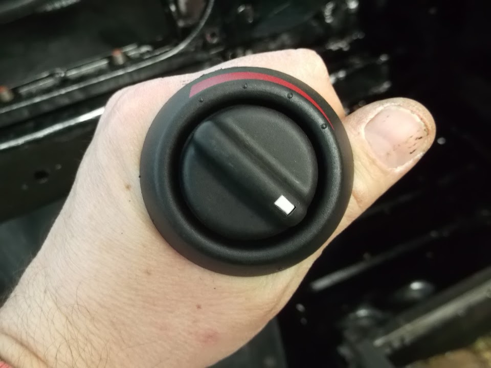


Then turn the dial anti-clockwise to ON:


So much for the 45 degrees of red heater markings. :icon_evil:

The only good news of this whole sorry saga, was that the best way to mount the value was like this.


This removes any potential fouling issues when the other heater hose is fitted. :cool:

I will need to make a new mounting bracket, but that should be straight forward enough.

( Famous last words. :rolleyes: )

Next job will be to check and fit the dash wiring loom.

I also want to dig out my completed headlight assembly to check it following a debate on Mac's build.

But that's all from me for now, Paul. :)
15 Mar 2014, 9:25pm
It's the little jobs that take the time Paul, it took me ages just to fit my throttle position sensor as the throttle linkage wasn't designed to use one.
At least you can tick another box!
Mac
16 Mar 2014, 1:32pm
Heater control

Hi Paul, great job buddy. Just wandered weather if you move the connecting rod to the hole nearest the centre of the valve then the ratio between the distance that the dial has to move compared to the distance the valve has to move will be greatly reduced?:eusa_eh:. Just read this back to myself and am not sure it makes sense?:bolt:. Tell me what you think. UFO17.

16 Mar 2014, 2:37pm
I think UFO might be right paul the closer you get to the pivot point the less distance the dial should have to turn, that said the further in towards the pivot point you get the more pressure you will need to turn the dial so it may be a trade off?
HTH
Mac
16 Mar 2014, 10:02pm
Mac & UFO17 - Thanks for the feedback chaps, I'll have another look at that.
I had briefly tried different holes, but the cable didn't line up very well.
However, since then I have hammered the bracket so much, another adjustment won't hurt.

- - - - - - - - - - - - - - - - - - - - - - - - - - - - - - -

Still inching along in the right direction...
Went for a lovely family pub lunch today and we could all sit outside in the sunshine. :cool:

Thankfully, I still managed to squeeze a few jobs in later in the afternoon.

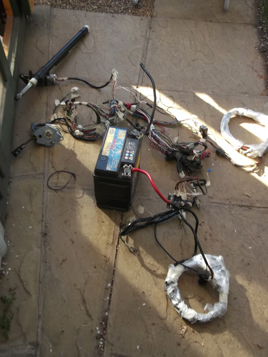
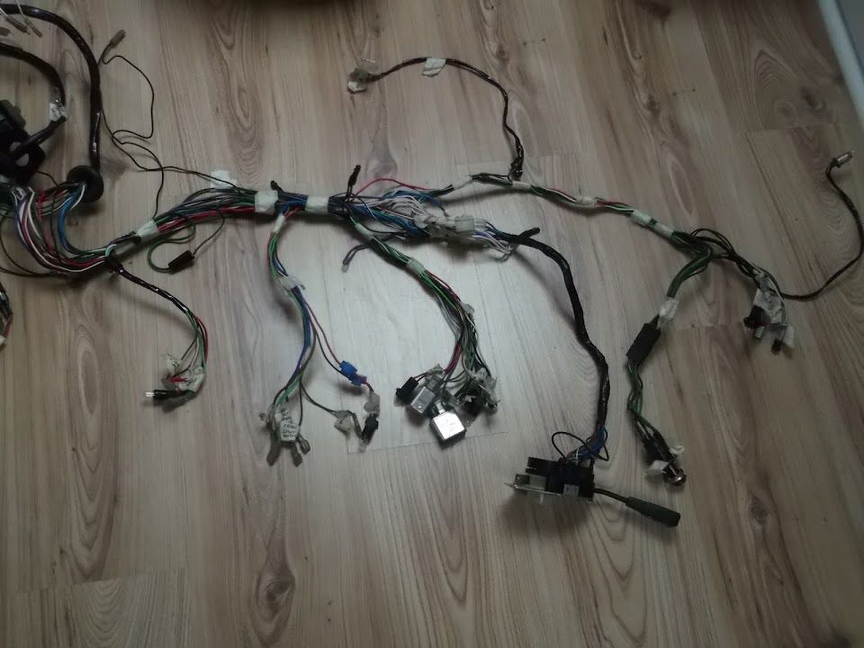
I laid out the wiring loom so I could start checking / changing things.


With the headlight switch connected, I could test the four bulbs for the dashboard dials.
( Speedo, rev counter, fuel & water temp. )


With these all working fine, the next job was to extend this loop for the oil pressure gauge.

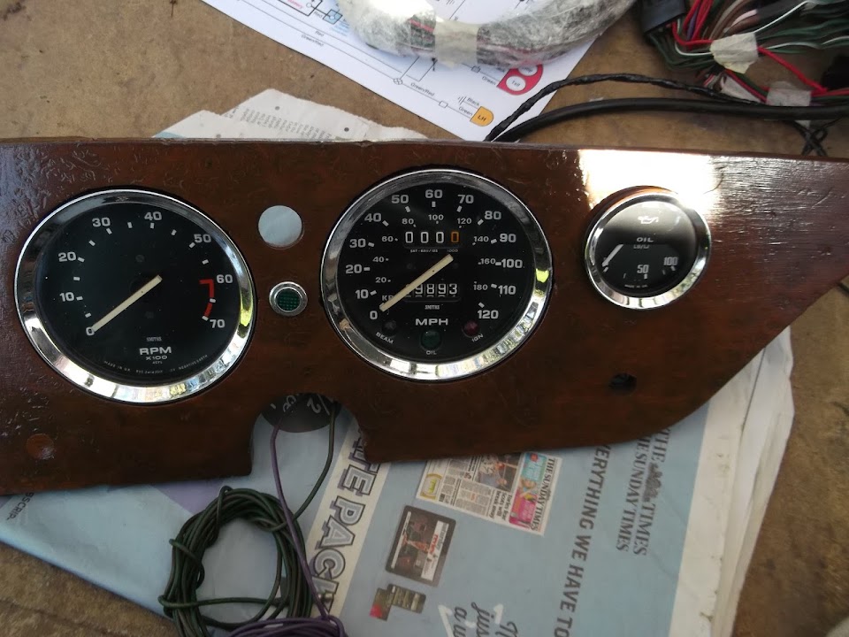
So I fitted a few things back into the dash board to get a better idea of the layout.


You can just about see the "spare" light I have with short wires sticking out of the oil pressure gauge.
( Note: The wiring for the light is the same regardless of which type of gauge I end up using. )


So this bulb needed to be joined to the speedo one, as that was the closest.

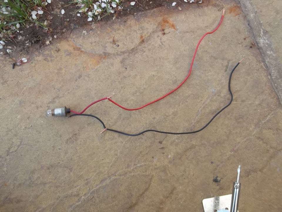
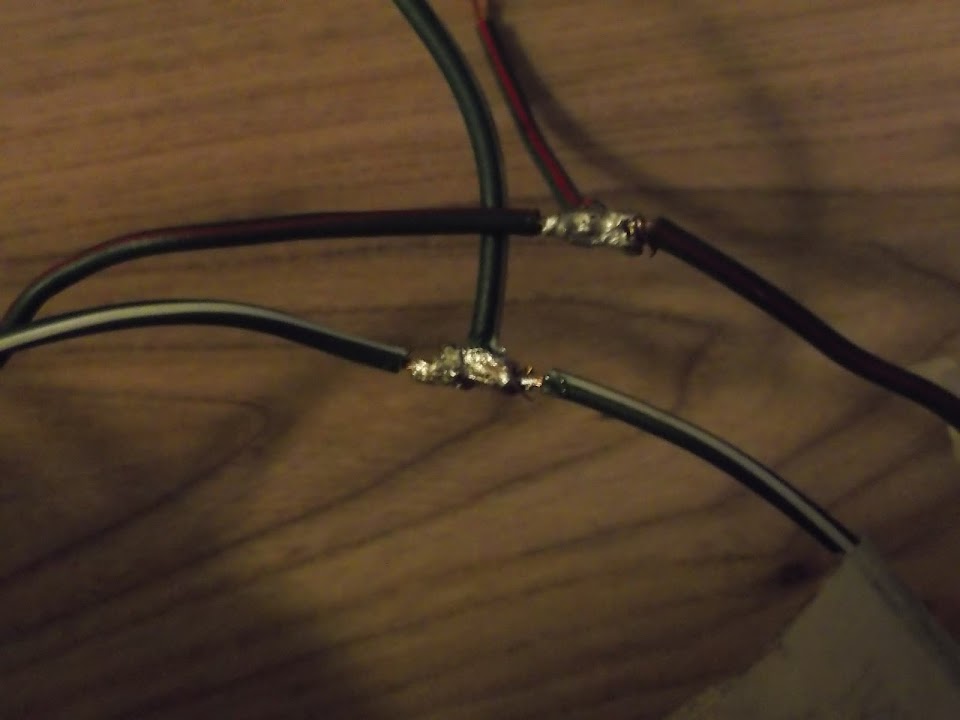
I picked out two short sections of spare wire for the first step in the process.


I added some solder where the wires joined.


Note: I did add a bit more solder after I had taken the photo.

A section of heat shrinking tubing then sealed the join.


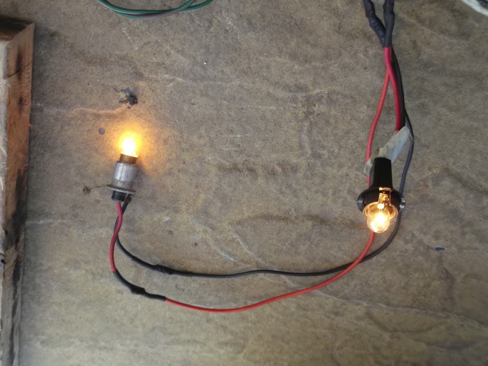
Then I cut the wires to the speedo bulb and joined them to the extended oil pressure gauge wires in the same way.


Funny how something as simple as a light bulb coming on can raise your spirits.


With the test complete, I could wrap the wiring up properly and tick that job off.


To pick on on Mac's reply above, this was a simple, but time consuming, little job.

Sticking with the wiring jobs for a bit, I started work on the side repeaters.


These spare wires match the existing wiring loom colours for the left and right indicators.

I will need to splice these into the loom behind the dash, before it separates into the front & rear sections of wiring.

I only had time for a very quick look at how much of the loom I need to "tuck away" behind the dash.


But before I tackle this properly, I need to do a couple of things.
- Go back & check old photos to remind myself how it was before.
- Work out a new route for the rear wiring loom, which needs to exit the bulkhead somewhere.
( I've sealed up the old holes for sending wires along the floor as there were a rust trap. )

The other bit of work I started today was the bulkhead bracket to hold the heater value.

I made a cardboard template and marked up some of my fresh steel.


I then cut this out, but added a "flap" for extra strength & a couple of bits that I may use for further bracing.


A session with the hammer gave me this.


The bracket will sit further back than this, once I've drilled a couple of locating holes.


I see how the bracket feels when welded up as it currently is, before deciding on extra bracing.

The only good thing about doing all these little jobs now, is that they would be much harder with the bulkhead mounted.

Until next time, take care, Paul.
17 Mar 2014, 8:43pm
All over the place...
I have a lot of plates spinning at the moment, but thankfully I got a bit of time on the car.

I wanted to measure the cable distance required to go from the battery to the cut off switch.

I put my new rubber battery rest in place.


But when I put the battery in I realised my donor didn't have a battery clamp in place...


Yes, the battery is the wrong shape to work with the new Spitfire clamp I bought.
( The clamp would short out the two terminals when their cables were fitted. )

A new battery was on my shopping list anyway, so I will just need to make sure it will fit properly.

For now, I simply switched the battery around and this time the clamp could work as intended.


Although I will need to trim a bit off the ends of the retaining bolts. :rolleyes:


Quick Question:
I've measured the cable distances I need for the battery cut off switch.
But what sort of amp rating should the new cables have, for both +ve & -ve?

- - - - - - - - - - - - - - - - - - - - - - - - - - - - - - -

The only other job I managed to do today was on the heater value support bracket.

You'd think that drilling two holes would be a simple enough job...


But I managed to break two drill bits in the process. :rolleyes:


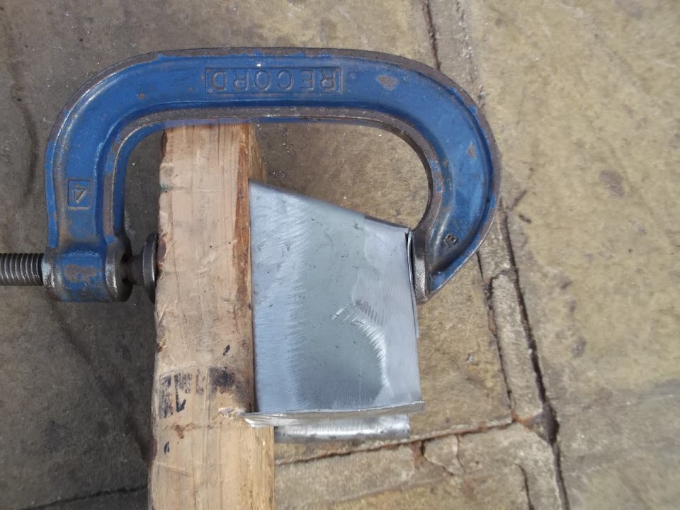
Clamping the edges together required a bit of wood to spread the load a bit.


But the welding itself was very straight forward, starting with the "flap" I'd left in the metal when I cut it out.


I then added just one extra brace to the front of the bracket.


Now I just need to drill a few more holes in the bracket.
- One to bolt the heater value support bracket to it.
- Plus four to mount the bracket to the bulkhead.


But I want to have a play around with the cable mounting location first.

Happy St.Patricks Day, Paul. :)
21 Mar 2014, 5:09pm
Catching Up - Part 1
Although I haven't posted any progress, I have been chipping away at my build.
This is a belated catch up covering the last few days, but not following a strict time line.

So in no particular order...

Moorcoft Motors
Went to visit this company, a small, back street, Triumph specialist near Potters Bar.


I had a great chat with them and they will collect my "Moon Rover" and do some work on it.
I just need to finish all the construction work first and then arrange a pick up date.
Then I can leave the engine work to them so that every thing runs as it should.
They will also suggest some upgrades to improve reliability if required.

Heater Control Value Mounting Bracket:
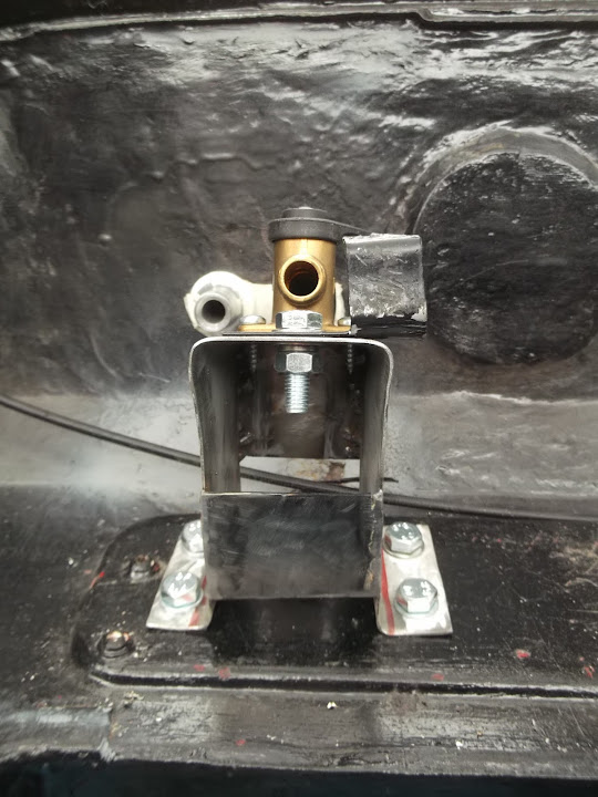
Before I bolted the bracket to the bulkhead, I went back & checked my old photos to find this.


As I remembered the hard lines ran across the bulkhead, but I couldn't remember where. :rolleyes:

Thankfully they all run in front of where this new bracket is going, so I drilled some holes in it & test fitted it.


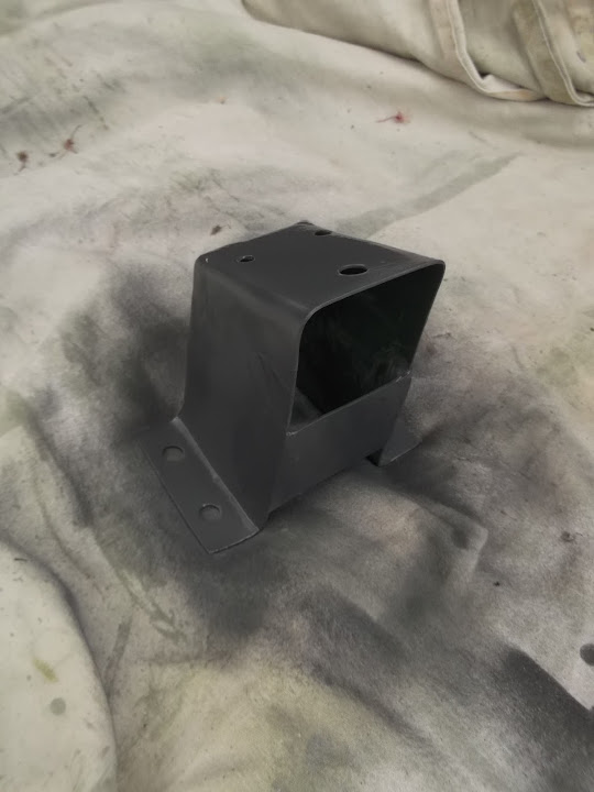
Then I treated the metal bracket and gave it a coat of primer.


Then all the welding got a coat of filler.


Before that was sanded down and another coat of primer was applied.


Rear View Mirror Mounting:
I still need to work out how the Cordite body will be extended to cover the Spitfire bulkhead / dash area.
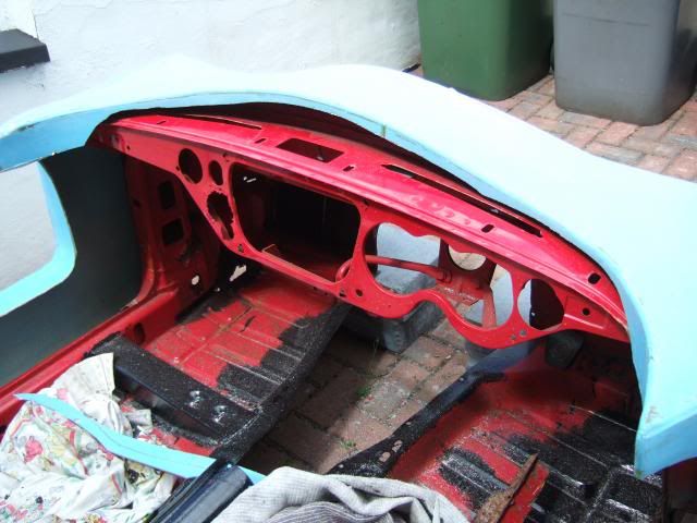
This was the "gap" when I was test fitting the body over the cut down Spitfire tub.


This photo had given me the idea that the ash tray hole could be used to provide access to mount the rear view mirror from below.

However this was the current view of that hole from above.


The ducting would be zip tied out of the way (see below).
So I just needed to take my angle grinder to a small section of the original heater control mounting panel.


To Be Continued...
21 Mar 2014, 5:10pm
Catching Up - Part 2
Believe it, or not, but I'd never used a pop rivet tool before the other day, so I did a bit of testing and quickly got the hang of it.

I wanted to beef up the zip tie holders that can be used with just their sticky pads.

So I looked at fixing the rivets from either side to see what worked best.


This was the "after" and I quickly noticed a problem.


Both options left metal in the way of the zip tie itself, so I hammered one end flat.


This gives me the option of using two slots, or I could just use one slot with the rivet head in place.


Then I drilled the the four holes I need to hold the ducting and "Y" connector in place.


Plus one extra point for a zip tie to "guide" the heater control cable on its way out of the bulkhead.


Bulkhead:
The Triumph garage said that setting up the Smiths electric oil pressure gauge would be a piece of cake. :cool:

They also had no idea why the previous owner thought putting a gauge in the engine bay was a good idea.

This was good news, as I had already committed to the bulkhead holes based on wires, not pipe work. :rolleyes:

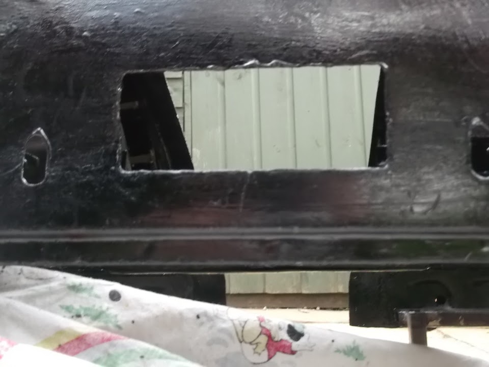
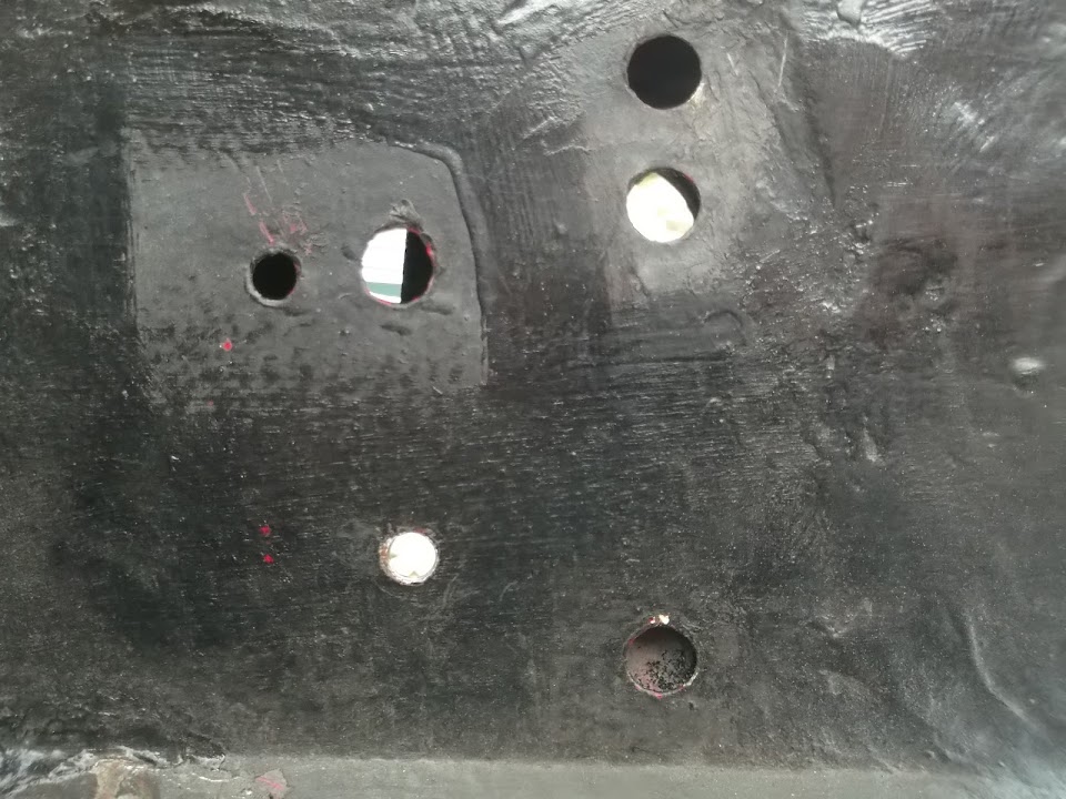
Here are all the holes...


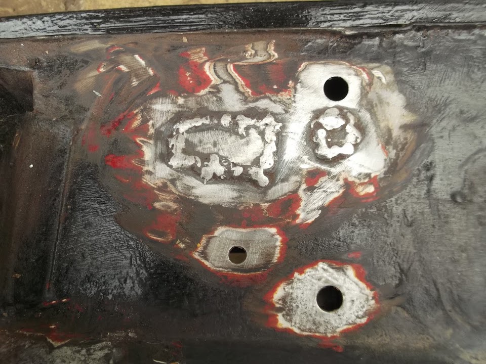
I did think about using a single patch to cover the three holes I didn't need.


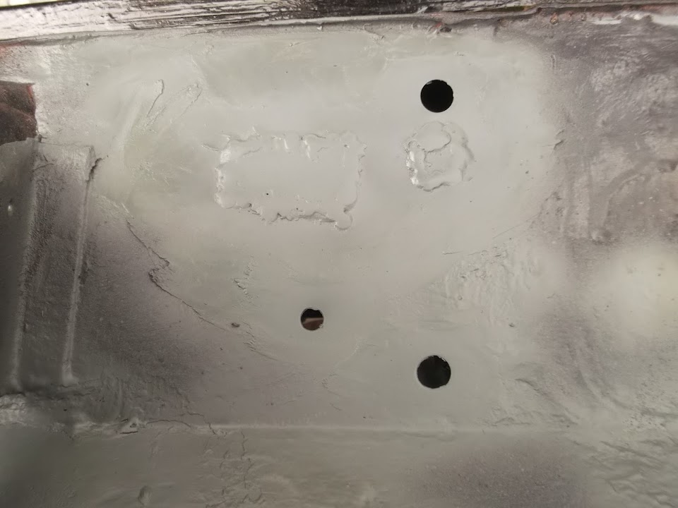
But took a bit longer and welded in two smaller patches instead & gave them the usual treatment.


I also treated the last remaining areas of the bulkhead.


I just need to put some filler on a few places before I can prep this final section for painting black.

This marks the end of the bulkhead welding until I can re-fit this to the chassis.

Then I will just need to weld in two crush tubes and the bulkhead will be done!

Shopping Update:
I have being ordering a number of little things recently to help finish off a few areas:
- New rubber rings/seals for the original Spitfire dials where they meet the dash from Rimmer Bros.
- Some longer 170 amp rated battery cables to connect the cut off switch from Ebay.
- Some hose separators to use on the micro heater plumbing from Ebay.


To Be Continued...
21 Mar 2014, 5:11pm
Catching Up - Part 3

Wiring:
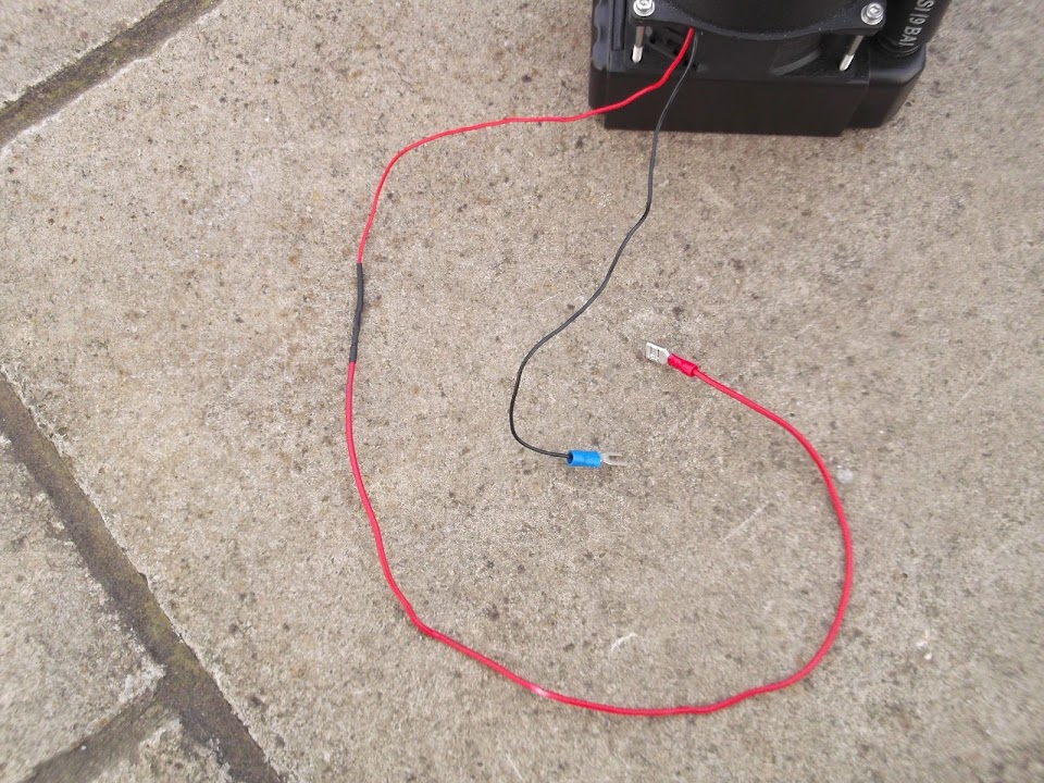
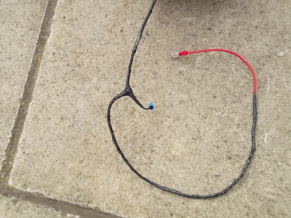
I extended the power cable for the micro heater and fitted a connector to the earth lead.


Then I wrapped the wires up ready for final fitting.


I also added two earth wires to the side repeaters.


These are long enough for me to join them up with the other earth cables behind the dash.

Given the fact I have to get the power wires into the dash area anyway, it seemed to make sense to do it this way.

Wooden Dash - Centre Section
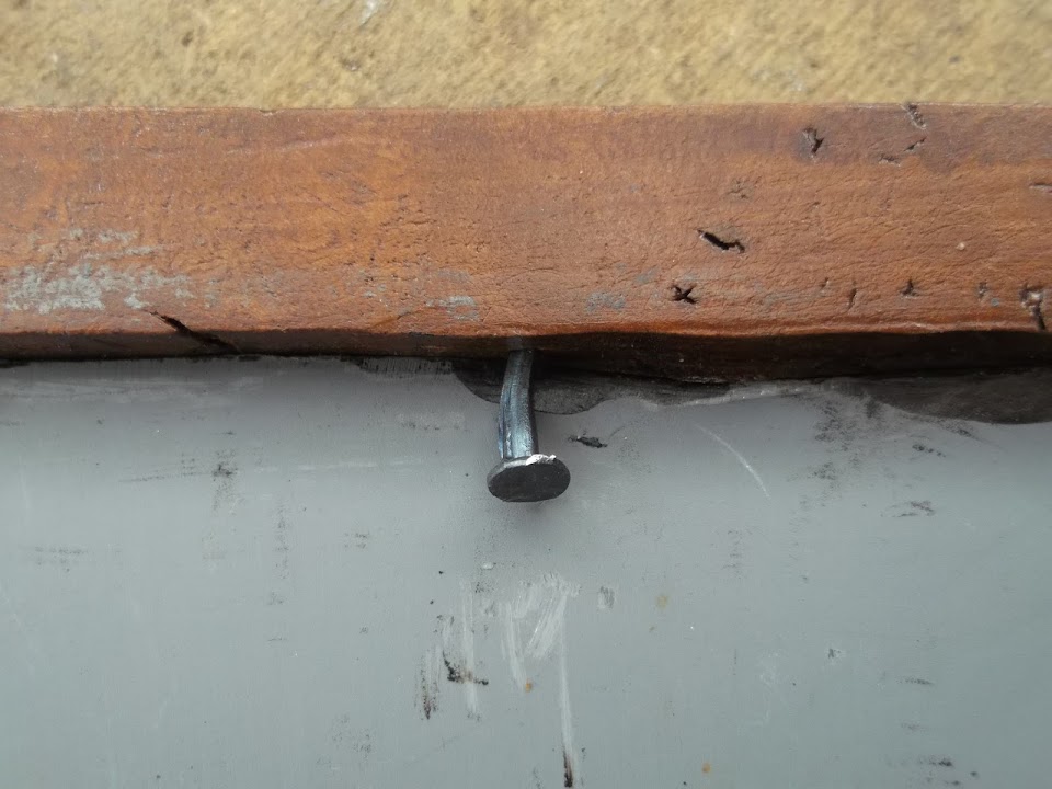
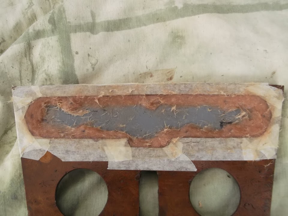
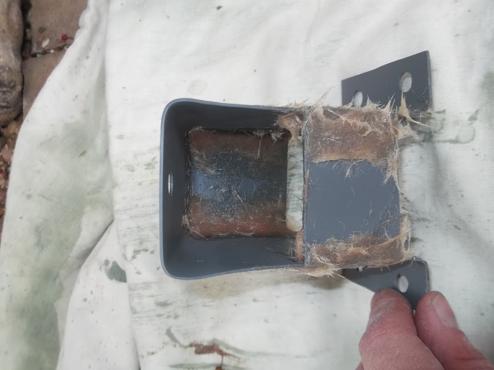
I wanted to make sure the "blank" for the old heater controls would not fall out while driving along.

So I started by hammering in some small tacks.


Before sealing the edges completely with fibreglass filler.


When this was set I could sand it all down and get a coat of primer on it.


This is what it will look like on the other side.


Although I am considering fitting the Wolseley 1500 badge I picked up from ebay here.


I think it looks pretty good, but as always, I am open to your feedback.

Dash - Final Adjustment
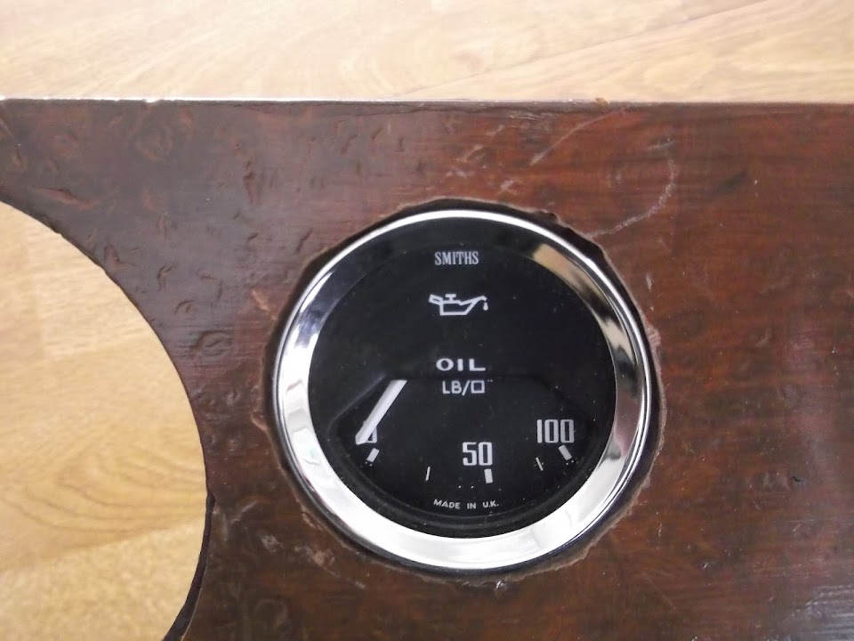
I have decided to "sink" the oil pressure gauge as it looks out of place just sitting proud.
This will take a bit of extra time, but I think it will be worth it in the end.
There is no real deadline for this build, so I see no point in cutting corners at this stage.

That's all for now as I've got to go, take care, Paul. :)

PS
Hopefully I will get a chance to reply to other builds over the weekend.
21 Mar 2014, 7:45pm
Cracking on now Paul! If you want my ten penneth worth the best mod you can make to your engine would be to go with a distributor less ignition system, whether it be megajolt, nodiz whatever.
I have yet to find an engine that doesn't respond well to being 3d mapped, they generally start and tick over better and the pickup is usually very much improved. Although you wont gain any extra power it will allow you to wring out every single pony that's there. Its not a difficult project and although I have had a set back with my Nodiz I'm absolutely sure I will be better off in terms of driveability once its sorted. Oh and if your thinking of performance upgrades I would always advise brakes first then engine, the other way round can occasionally end up badly :-)
Keep up the good work
TTFN
Mac
22 Mar 2014, 6:41pm
Mac - Cheers, your advice is always welcome. :cool:

- - - - - - - - - - - - - - - - - - - - - - - - - - - - - - -

Making a mess of the dash...
Whilst I liked the view of the oil pressure gauge from the front.


I knew I was never going to be happy with the way it sat proud of the dash compared to all the other dials.


But as I said yesterday, I want to do the best job I can, so it the dial needed to be "sunk".

So I marked up the edge of the dial.


Then set up my drill so it wouldn't go down too far.


Unfortunately, the wooden drill bit didn't really work and I had to use a metal one instead.

I also used a craft knife, but to be honest the result was a bit of a dog's dinner. :icon_sad:


Because although the gauge looked good from this angle.


It was a bit of a mess from this one.


So I wrapped up the gauge and put some wood filler into the gaps.


Not sure if this will work, or not, but I'll give it a go and see what happens.

Other Jobs
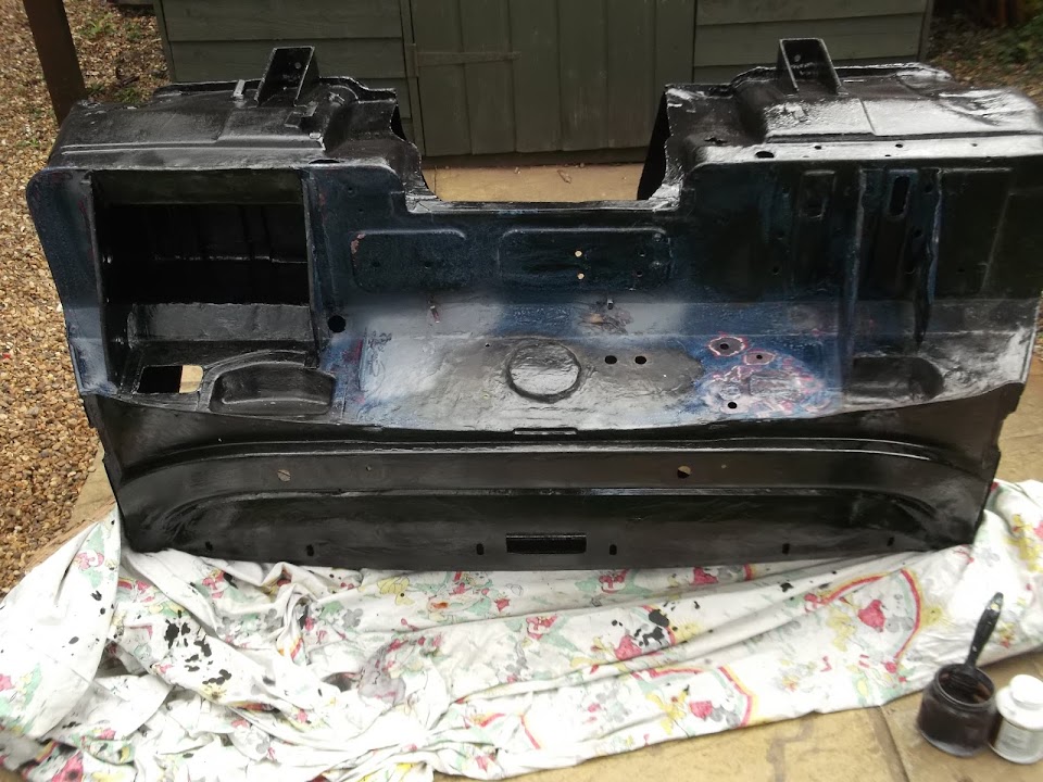
I got some fibreglass filler on the welding I did over the surplus bulkhead holes.


There were three other areas that I needed to patch up as well.


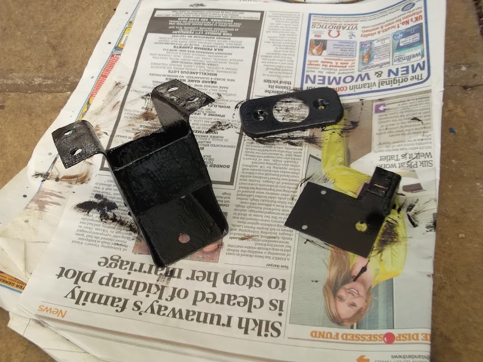
Then I painted the two heater control value brackets and the steering column cover.


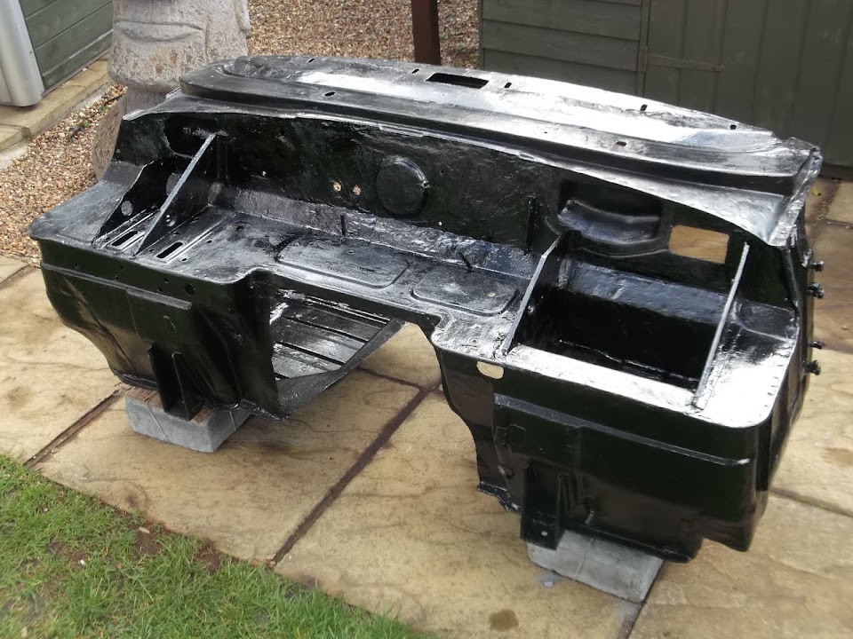
While I had the paint out, I covered all the remaining parts of the bulkhead, apart from the areas with filler applied.


So once the filler is sanded down and painted, the bulkhead will finally be the same colour all over. :cool:

Cheers, Paul. :)
22 Mar 2014, 11:06pm
Paul, why don't you buy a hole drilling set? It would make your life so much easier!
I bought one last year from Aldi, and I was in there today, and they have them on sale again only £9.99.
They are really good quality, I used them to drill all those holes in my steel wheels, and they are still sharp!
23 Mar 2014, 12:44pm
Scottie - I do have a cheap hole drilling set, but not one for the size I needed. :rolleyes:
Although I might still try to pop into Aldi next week if I get the chance.

- - - - - - - - - - - - - - - - - - - - - - - - - - - - - - -

Bloody Showers...
I managed to get a quick break in the rain to get a little bit done.

I sanded down the fibreglass filler applied yesterday and gave it a coat of paint.

Here was where the surplus holes were.


And this was the bulkhead as a whole.


This was quite a landmark moment, because after five months of work, the bulkhead is finally one colour all over. :cool:

There are still a few odd jods to do on the bulkhead, but the end really is nigh.

The only other thing I managed to do was tidy up the wood filler in the dash hole & stain it.


To be honest the circle around the oil pressure gauge still looks like I chewed the hole out with my teeth. :icon_sad:

But the overall look of this project will be "battered old ex-race car", so maybe I will get away with it. :rolleyes:

I had just finished the wood staining when the sky went black, so I packed everything away & covered the bulkhead (again!).
Note: The cover is spread out so it doesn't touch any of the wet paint below.


Taking a break...
I have decided to stop work on the car now for a short time, at least a week, maybe two.
I simply have too many other things to do at the moment and they are being neglected in favour of the build.
Well, given the choice of sorting out house admin (bills, statements, etc.) or the car, what would you choose? :icon_wink:
Hopefully without any car distractions I can quickly sort out everything else and then get back to it ASAP.

And Finally...
I know I have spent a very long time repairing / modifying this bulkhead.
But I take great pride in how much my metal working skills have improved since I started on it.
It should not be too long now before I can build the "join" between the bulkhead & the rear frame work.
At which point it will feel like I finally back to the main road to building the Cordite.
Although my initial focus will not extend beyond the "Moon Rover" stage.

So until next time, take care, Paul. :)
27 Mar 2014, 7:20pm
Hi Paul, been so busy on my seats, Iv'e not looked at your thread for a while.

Like you said if you keep inching along ( always provided its in the right direction!) You will get there in the end.
That's my philosophy too!

Keep at it mate!

Scottie
30 Mar 2014, 8:27am
Scottie - Cheers. :cool:
I will now be able to look back at the bulkhead and see what chipping away can achieve.
The rest of this build will be an extension of that approach until the car is done.
The reality is there is so much left to do, that I don't really want to think about it.
But by sticking to the job in hand (no matter how small), I know I will get there in the end.

- - - - - - - - - - - - - - - - - - - - - - - - - - - - - - -

Well, I've been pretty good at focussing on "non car" activities recently.
But there is a little bit of process to report since my last update...

Wiring Loom - Part 1:
I brought my loom indoors to make checking where to adjust the wiring a bit easier to do.
This also meant I could chip away at it in the evenings when it was dark outside.
The only down side is that the quality of many of the indoor photos are pretty poor. :(


The original Spitfire 1500 had a separate side light & front indicator unit.
However, for my Cordite, I've got a headlight with a side light built in.
So I took this opportunity to re-route the original wires for these items and the two car horns.

This is the original cable routing before, with the headlight & side light as two separate cable runs.


The next photo is a bit more of a close up before I started unwrapped the wires.
Note: There is a collection of earth wires joined together in a little "siding" of their own.


This was my revised cable route:


Notes:
- The bundles of wires at coming from the top of the photo will start at the bulkhead.
- The wires for the two horns exit to the right and point towards the top of the photo.
- All the other wires feeding the headlights, side lights & indicators run off at the bottom of the photo.

There is more work required on the lighting wires at the bottom, but, for now, I wrapped up the rest.


- - - - - - - - - - - - - - -

I knew that I had already removed all of the Spitfire heater wiring when I thinned out the loom. :rolleyes:

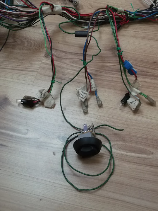
Therefore I wasn't sure how hard it would be to add wiring back into the loom for the new heater fan speed switch.

So you can imagine how happy I was when I traced the wiring I needed to use and found this connecting block.


Which lead to my collection of spare wires where the original heater wire was just waiting for me.


This may not be the original Triumph set up, but it made the re-connection a piece of cake. :cool:
( There have been very few "easy" jobs on this build, so I'll take the small victories when I can! )


I still need to fit a wider blade connector on the other end, as the new switch is a different size.
But I will do that when I have measured just how long this wire needs to be.


Note:
I've already sorted out the other wire for this fan speed switch which runs from the micro heater itself.

- - - - - - - - - - - - - - -

These big blue connectors had been used to connect the fuel gauge light to the heater switch lighting.


The heater wires were already gone, so I removed the connectors and re-joined the wires together.


This made the initial wrapping of the various wires behind the centre dash section easier.
( L-R = Water temp. gauge, headlight switch & fuel gauge. )


There will be one more run of wires coming from the main loom into this area.
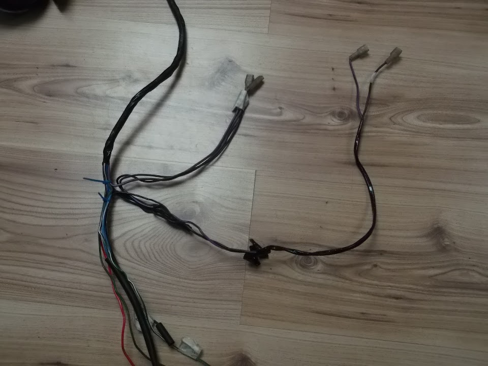
- The fan speed switch wire (see unwrapped photo above).
- Plus an extra earth cable I am going run from the loom to the micro heater's earthing point.

- - - - - - - - - - - - - - -

As part of my general "tidying up" of the wiring, my donor came with some nice "trunking" for the headlight wires.


The only problem was finding a way of holding it in place next to the rubber grommet in the headlight shell.


I'd tried simply using electrical tape to keep it in place, but it just wouldn't hold, so I used some tiny zip ties.
( These came with my crimping tool set. )

One went on the cables.


Then another two went around the "trunking" on either side of the first zip tie and that seems to work.


I've started working on a couple of other sections of the loom, but I'll cover that when I have finished the work.
30 Mar 2014, 8:28am
After an epic gardening session yesterday, I was also able to get a little bit done outside before the sun went down...

Battery:
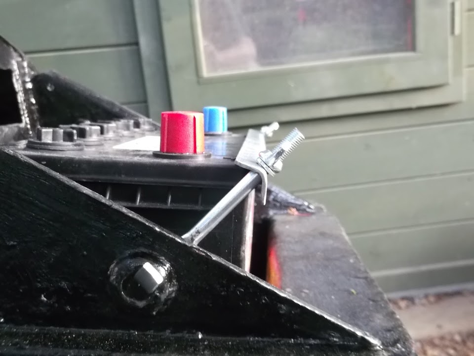
I test fitted my new battery, but the new retaining bracket did not want to line up / work properly.
( Admittedly, the battery sits much lower than standard in my home made battery box. )

Thankfully I found something suitable in the box of bits that came with my donor car.


Although I still had the issue with the length of the bolts.


So out came the angle grinder to trim both the width of the bracket & length of the bolts.

Then I added the foam strip that came with the new bracket.


So now it all looks a lot better.


- - - - - - - - - - - - - - -

Battery Cut Off Switch:
I had also bought two new battery leads:
- One for the battery terminal to the cut off switch.
- The other from the cut off switch to the bulkhead earth.


It was only when I came to fit them that I noticed another school boy error.


I'd measured the "ring" end of the original battery cable (bottom right) and made sure the new ones matched.

However, what I should have done is measure the size of the cut off switch bolts, as they are bigger. :rolleyes:

My temporary fix was to open up the "ring" like so.


The next step was to drill two holes in the bulkhead so the leads could be connected to the switch.


Unfortunately, "Amateur Night" continued as I managed to make a hash of this simple task too. :(

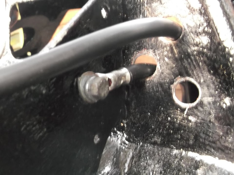
I've actually ended up with three holes to avoid a severe bend in one of the leads. :rolleyes:


The only good news is that I have had plenty of practise welding up holes in this bulkhead.

So this is the route the battery cable will take going into the bulkhead.
( Some new rubber grommets for the holes have been ordered. )


Then the return cable will come back out here and connect to the original Spitfire earthing point.
( Other cables will also be attached to this point. )


At some point I will a few holes in the bulkhead for some pop rivets to hold some zip tie mounts.
Then I can use the zip ties to keep the two cables apart and tuck them neatly out of the way.

But that's all for this update, so until next time, take care, Paul. :)
31 Mar 2014, 2:03pm
Starting to come together really nicely matey!
At one of the shows the other year i picked up a "big pack-o-gromets" some blanked off, some not. I rate it as one of my best under a fiver purchases as you don't realise how useful they are until you've got them. :)
1 Apr 2014, 6:22pm
Dave - Cheers, I know it has taken me a long time to get this far, but the bulkhead does give me hope.
You're right about things like grommets, as all the little "bits & pieces" required to build the car soon add up!

- - - - - - - - - - - - - - - - - - - - - - - - - - - - - - -

Here is round up of what I've managed to squeeze in over the last few days...

Wiring Loom - Part 2:
I'd found the two "power" wires I needed for my side repeaters running from the indicator switch through the wires behind the dash.


I plan to fit the side repeaters to the main bodywork, rather than the flip up bonnet as seen here on tlrtone's build.
( Don't get me wrong, they look good there, but it seems like a long wiring route to me. )


Rather than cut these power wires, I simply "skinned" a small section of insulation off them.

Then I could wrap the ends of two small lengths of "spare" wires in matching colours to each wire.


I just needed to add some solder before wrapping the "T" junctions


With the "power" wires for the side repeaters wiring taken care of, next up was providing then with an earth feed...

- - - - - - - - - - - - - - -

There was a "spare" earth wire running through the loom behind the centre of the dash, originally used for the old heater.


But I wanted to add three extra lengths of wire to it at this point.
- Two to correspond with the left & right side repeater wires I'd just set up above.
- Plus one more to connect with the earthing point I'm using for the new micro heater.

I figured trying to wrap lots of wire together would just make a big mess.

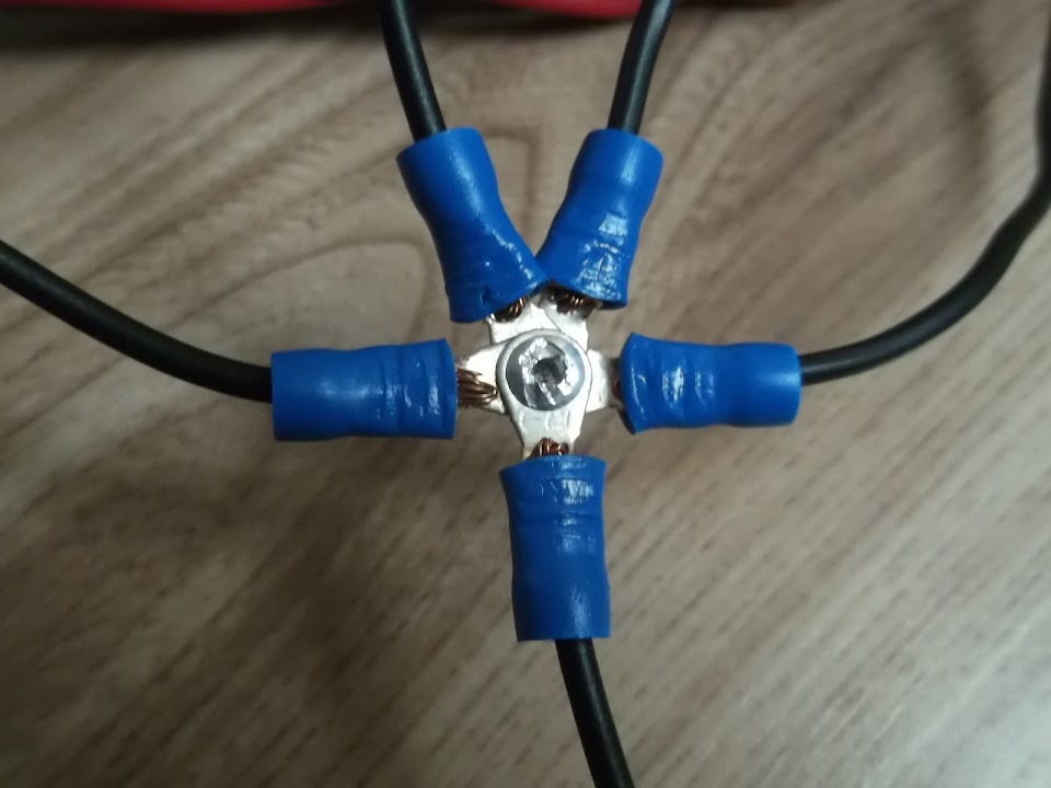
So instead I used 5 of the small ring/eye connectors that came with my crimping tool.


Together with my new pop riveting skills, I could now make a five way connection like so.


The wiring behind the centre section of the dash now looked like this.


With the new earth wire and the previously connected green fan speed switch wire coming straight down.

But before I could finish wrapping up this section of the loom there was another job to finish first...

- - - - - - - - - - - - - - -

When I first stripped my donor, there were two "random" wires in the engine bay not connected to anything.

Later on, when I started thinning out the wiring loom, I discovered both these wires ran to the oil warning light.

But after looking at more wiring diagrams, it turns out one of these wires is actually for a PDWA switch.
( Pressure Differential Warning Actuator )

This is linked to the fact I am running the dual (tandem) brake system from my late model 1500 donor.

The "plug" end of the cable looked like it had seen better days & may never have been used at all.


Also the PDWA wiring does not appear on any of the UK wiring diagrams I have, only the USA ones.

Plus the corresponding warning light on the speedo is simply marked "Oil" & makes no reference to brakes.


So I have decided to remove the PDWA wiring altogether to keep the wiring I do want much simpler.

The only problem with this "master plan" was one end of the wire was in the engine bay section of the loom. :rolleyes:


So I unwrapped this a section at a time, adding tape back to hold the cable routes in their original positions after I'd removed the wire.


Eventually, I had all the surplus wires I wanted to remove in one place.


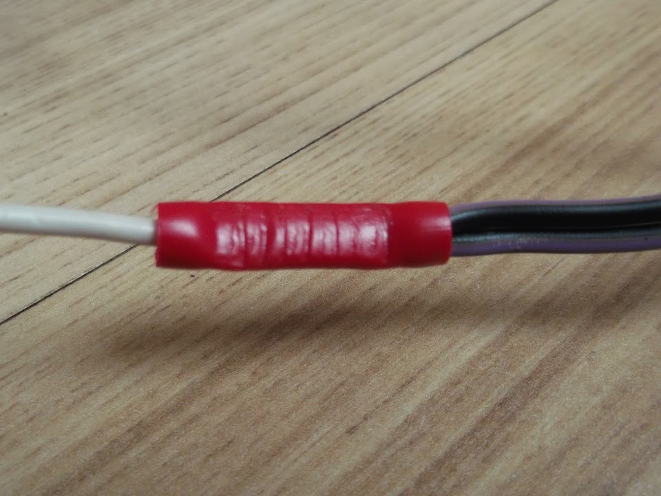
Just one of these two black/purple cables needed to be connected to a single white wire in the loom.


But just to be on the safe side I joined them both to the white wire.
( It has taken me a while to start using these crimp connectors that came with my pliers, but they are handy. )


This was the pile of spaghetti for the area behind the steering wheel before I removed the PDWA wires.


But before I started to tackle the rest of this mess, I went back to the centre dashboard wiring...
1 Apr 2014, 6:25pm
Wiring Loom - Part 3:
With the PDWA wires removed, and the other wires running through here double checked, the centre dash section was now done.

So I wrapped it all up and it was nice to see one small part of the much bigger job complete. :cool:


In addition to the side repeater "spurs" pointing upwards in this section, there is also the ignition key wiring.

- - - - - - - - - - - - - - -

I'd found a broken wire from one of the previous owners mods when I dismantled my donor.


This had linked the rev. counter earth to the high beam warning light earth.

However, this earth wire also had been "flattened" at some point.


So I decided to sort this all out properly while I was knee deep in wires anyway.

I wanted to keep the three speedo warning lights on a separate cable route anyway.

So I added the high beam warning light earth wire to another earth wire in the main loom.


As I'd already sorted out the oil warning light, I could now wrap the wires for these three bulbs.


Now I just needed to sort out the earth lead for the rev counter, but there was another problem...

- - - - - - - - - - - - - - -

I have been working with my notes and old photos, but the earth leads & dial bulb marked for the speedo just didn't look right.

In fact, I couldn't find a nice way to route most of the wiring while keeping the dash layout the way the previous owner had it.


After a lot of beard scratching I had convinced myself that the dials must have been fitted the wrong way round. :rolleyes:

Sure enough, a quick search of Google images gave me a standard layout with the speedo on the left & rev counter on the right!

:rant:

Once I'd calmed down a bit, I simply re-arranged the dials on the floor and instantly the wiring lengths/routes made more sense. :cool:


So it turns out that the oil pressure gauge bulb (far right) is actually an extension of the rev. counter bulb, not the speedo one.

Whilst it was good to know I can trust my instincts (occasionally!), it had been a frustrating waste of time.

The rev counter earth wire was set up just like the high beam warning light (1 earth wire becomes 2).

Any with that final fix for this section of wires in place I could finally see the rough layout I needed.
Note: This is not how they fit, just the separate routes I am going to have.


Then it was time to wrap up the vast majority of the wires behind the steering wheel.


This section also includes the wires that connect to the brake light switch behind the brake pedal.

I've left wires for the flasher unit and the hazard flasher unit unwrapped for now, until I can check where they are fitted relative to everything else.


- - - - - - - - - - - - - - -

When I first thinned the loom out, I cut one wire in error from the connection block that goes to the indicator/horn switch. :rolleyes:

Rather than attempt to fix the mess I'd made of the original connecting block, I simply added an extra connection.


However, for this to work, I had to wrap a "bend" in the rest of the wires to create some slack.
( As my previous butchery had left the wires too short. )


Whilst this is clearly not as tidy as the original set up, it will work well enough for me.
1 Apr 2014, 6:26pm
Wiring Loom - Part 4:
I continued working my way along the loom until I got to the section of wires near the fuses.

This included the second (of two) mistakes that I'd made when thinning out the loom the first time.

I'd cut out the green & black wire to the left with the masking tape on it in error, but is was now too short to rejoin at the fuse box.


In addition, there was a "stray" earth lead that wasn't going to fold up/tuck away neatly either.


So I used two more of my red connecting tubes to tidy up the wires & their routes.
- The green & black wire now joins one of the green wires a bit earlier than at the fuse box itself.
- The earth wire is now a single lead to "earth", with the rest of the wire the right size to tuck in nicely.


Which meant another section of the loom could be wrapped up.


Note:
The collection of wires heading off to the bottom of this photo are for the rear lighting.
But I still need to work out the route they will take from the bulkhead through the rest of the car.

- - - - - - - - - - - - - - -

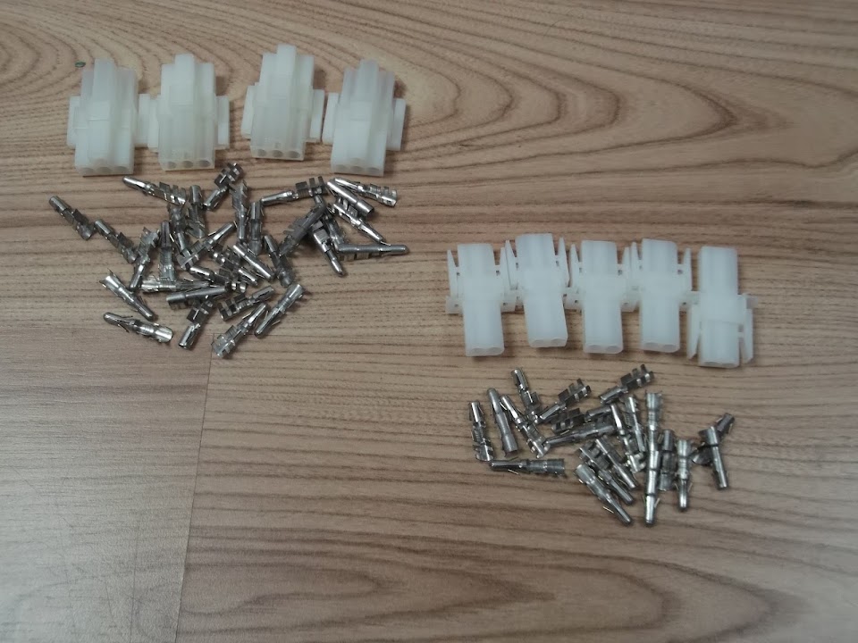
The next batch of wiring work could only start when the new connecting blocks I'd ordered arrived.
( 4 x 4 way connectors + 5 x 2 way connectors. )


I will be using these to join the old loom to the wiring for the front & rear lighting + side repeaters.
However, there was only so much I could do indoors without the full loom being laid out across the chassis / bodywork.

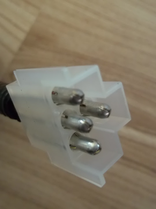
So I started by simply fitting one side/half of a 4 pin block to the headlight wiring.
( It is amazing just how long ago I started playing with the wires for these things. :rolleyes: )

There were three original wires, plus one new wire I'd added for the built in side light.


These wires were then cut to size & fixed into the pins.


Note:
The cable clamps were too "flat" at this point & needed to be squashed a bit rounder to fit inside the plastic block.


But once I'd got the hang of it, it was simply a matter of taking my time and repeating the process.

Eventually I had completed the other headlight cable and the wiring for the two front indicators.


Obviously the indicators only need a two pin connector.


The other halves of all these blocks will be fitted to the main loom, when I can finalise the wiring route/length required.

Note:
Just before I wired up the second headlight, it dawned on me it would be handy if each block was wired the same way.
So luckily either headlight will plug into either side of the loom, provided I remember to do the same with the loom block.

- - - - - - - - - - - - - - -

In addition to working on the indicator wiring, I've also been thinking about their location on the car.

Micky1Mo posted this photo of his Navigator/Spitfire hybrid the other day.


KISS principles would suggest doing something very similar on my own build to save both time & effort.

Mind you, it will be a while before I need to finalise this plan, so back to the wiring loom...

- - - - - - - - - - - - - - -

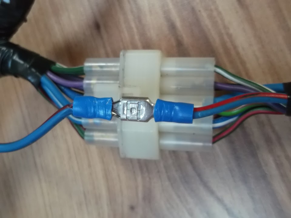
My final bit of work on the loom for now was to add two small blocks to the side repeater feeds.


I have set the connectors up so that the 'female' ends will be on the loom & the 'male' end on the lights, etc.


As before, the other half of these blocks will be added when the wires to the lights themselves are cut to length.

I must say I am really impressed with how easy these connectors are to use and how professional they look. :cool:

- - - - - - - - - - - - - - -

Finally, I'm also making good progress on "non car" stuff, but need to concentrate solely on that again for a while.

So until next time, take care, Paul. :)
1 Apr 2014, 8:29pm
That lot looks really good Paul, I'll know who to ask when I need to do mine!

My wiring looks a real mess at present!
3 Apr 2014, 8:21am
Scottie - Thanks. :cool:
I am actually enjoying the wiring and now have a much better idea how it all joins up.
Also, I really like the look of those connecting blocks from AES (Auto Electrical Supplies).

- - - - - - - - - - - - - - - - - - - - - - - - - - - - - - -

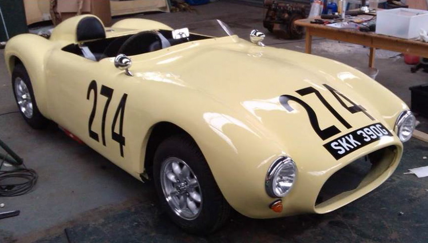
I know I am supposed to be doing other things, but I loved the photos in yesterday's "Ribble News".

Car #274 is a Pilot/Spyder body with a Navigator/Cordite bonnet fitted.


I have similar alloy wheels, the same type of chrome bullet side mirrors, similar lighting, etc.

So this actually gives a pretty good impression of what I am trying to achieve.

Although, I prefer to use racing roundels if I decide to put #7 (Cordite kit number) on my car.

The other thing I like about this is the way the front indicator still looks good at a downward angle.

I'd rejected this idea when I tested it with my, much larger, Land Rover rear indicator lens a long time ago.


But I now have the same classic mini front indicators to use and so I will copy this idea.

Yes, I know, it was only a few days ago that I said I would copy Micky1Mo's indicators in the grille idea. :rolleyes:

Perhaps I should drill some holes in the bonnet straightaway before any more photos are published! :icon_wink:

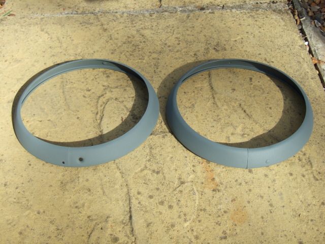
Finally, I had also got to the bottom of the retaining the headlight rim (see Mac's build).

The 1500 used a different headlight fitting altogether, so I'd order two second hand ones.


But one came with a hole for a fixing screw and one didn't.

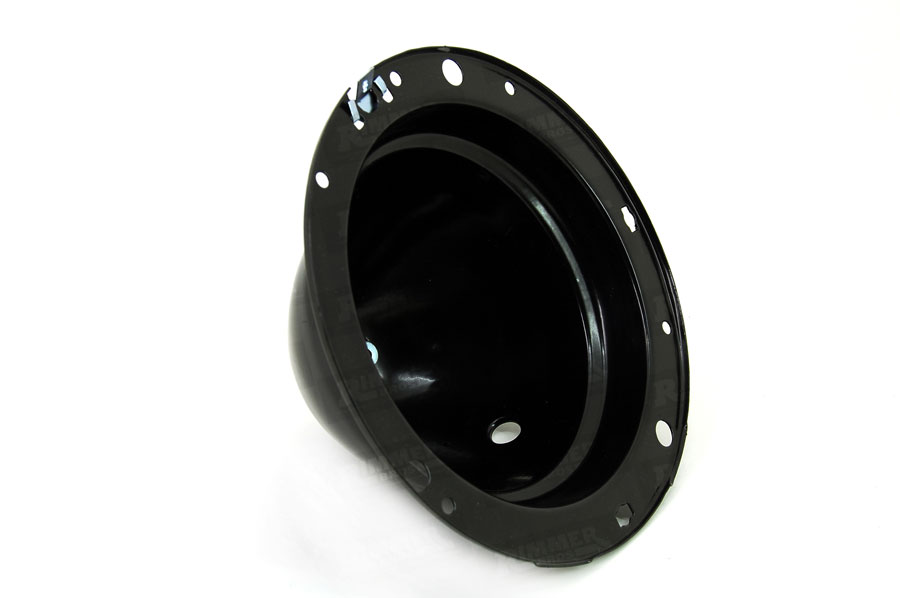
Anyway, I had brought a complete headlight assembly indoors when working on the wiring loom.

But a quick check with Rimmer Brothers showed I was missing the retaining clip in this photo.


So I need to see if I set up something that will work with the box of clips I have.

Plus I will need to drill a hole in the headlight rim that currently doesn't have one.

Anyway, that all for now, as I really need to go.

Cheers, Paul. :)
3 Apr 2014, 1:14pm
Indicators

[IMG][/IMG]
4 Apr 2014, 7:59am
Scottie - Please don't show me more front indicator options, as you know what I'm like. :rolleyes:
( See below for confirmation. :icon_wink: )

Mac - Thanks for the link, I've put an order in for a couple of those clips. :cool:

- - - - - - - - - - - - - - - - - - - - - - - - - - - - - - -

KISS and just stick to the plan...
Perhaps it might be better if I don't follow other builds on here, as I appear to be easily lead. :rolleyes:

But playing with the wiring loom was bound to get me thinking about my lights wasn't it?

This was always my plan for the back of my car...


Note: Obviously, everything would be nicely spaced apart and aligned horizontally.

Then I saw what Micky1Mo & HouseMartin had done at the back of their G-46s...


Archived forum photo


Part of me was convinced that fitting a single rear light cluster would be less effort.

So, before I knew it, I'd bought a cheap pair of Austin units on Ebay that looked like they might do the job.


These units were actually a lot bigger in real life, than they looked in the photo or I expected. :rolleyes:

Either that, or the back end of a G-46 really is HUGE!

So there wasn't really an idea position to fit them on my Cordite bodywork...

Option #1:


Option #2:


I think it would be possible to make these fit with a bit / a lot of work.

But quite frankly, I've already got so much work to do as it is, so these lights will not be used.

Instead, they will eventually be going back on ebay, unless anyone on here wants them.

And I will stick with the original rear lighting that I have, although I might rearrange the layout a bit...


Decisions, decisions, but thankfully I can worry about that another day.

Take care, Paul. :)