This is a read-only archive of the old Madabout Kitcars forum. New posts and replies are no longer possible, but every thread is still here to browse and read.
This thread has some very in-depth engineering and description of the suspension requirements. Unfortunately it is also pretty dense and takes a long time to digest. Someone might find it useful: http://reversetrike.proboards.com/thread/343
I think hes an engineer, they love crunching numbers.
To many numbers to be honest ,he is over thinking it.
People can make it look like a black art, but its not complicated if you keep it simple.
If you guys want to start from scratch type or heavily modified projects buy Susprog3.
It is a great suspension program and it will punch out s/loads of data,I dont look at all off the data because it is what it is and there are things you cant change and there are things that make no difference.
I only use about 4 or 5 key things.
You have to spend the time inputting the data which can be overwhelming at first but it is worth it.
If you are not happy with something you adjust it in the program and run it in bump or roll and you recheck the dynamic figures.
Hi
I'm in the middle of mocking up the adaptor plate. I've had a rough one cut to start with and I've made one up from the gearbox to place on top to see where bolts etc pass through. I think I'm going to have the final one made in alley as I need to have it 20mm thick to clear some bolt on the gearbox diff.
Anyone know of cuc guy's doing alley plates?
ian
Hey, if you google turbonutter and his Stratos replica with Alfa V6 fitted to an MR2 Toyota gearbox you'll find photos and some advanced tips. He may even have CAD files that could be of some use in your MR2/FordV6 adaptor.
Cheers
Ross
I've already been in touch with him. He had a local to him motorsport firm do all the measuring and manufacture. Said it wasn't cheap. They also have the files.
I've drawn up my own adaptor plate and with a vernier measured the hole dimensions on the trail plate I had done. I have a friend who works with perspex and he has cnc'd me a trail jig.Fits onto the V6 crankcase perfect and all holes line up.
Next up is to measure the Mr2 gearbox and have another jig made up to check alignment of the two.He will load it onto a memory stick for me and then I'll have it machined in 20mm allet plate.
Hi Ian, are you putting a spacer on the end of the crankshaft to push the flywheel/clutch out 20mm to match what the MR2 gearbox had with its Toyota engine?
I will not be using a spacer on the flywheel. As I'll need a flywheel to go from the ford crank to toyota clutch I will have one made the 20mm or so thicker. A company here in the uk TTR racing do them from around £300.
I'm planning on using a stock format toyota clutch and release bearing so I can keep the toyota starter motor which is mounted on the gearbox. I'm trying to keep to stock equipment wherever possible and not go to over the top.
Thanks Ian, I'm trying to visualise this.
So you are having a new Flywheel made that will have it's friction face further out from the crank end to match the original position of the Toyota clutch/flywheel interface (and this is 20mm because that's the thickness you need for your adapter plate). And the new flywheel will also have its starter teeth/ring gear in a place to suit the original Toyota.This new flywheel will have a bolt PCD pattern to match your Ford V6 crankshaft. It will have a friction surface to match the original Toyota clutch you are going to use. The nose of the Toyota gearbox will be supported how? I guess either a bearing in the crank elongated by 20mm or by an extension of the transmission shaft. Or perhaps the transmission shaft is long enough anyway or isn't supported in the crank?
Wow - its a lot to get my head around and that's without even thinking about the clutch actuator!
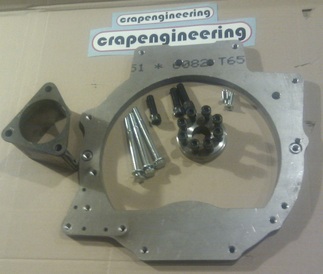
Clairetoo's locost posts and her company Crap Engineering make an adapter to fit the Mazda V6 to the Mazda MX5 gearbox that looks like this:
as you can see the position of the starter causes a few headaches in this setup. She chooses a spacer on the crank to avoid having a new flywheel made and because she wants a light flywheel.
cheers
Ross in NZ
Yes. The flywheel will be made to bolt to the ford V6 crank then mate up to the toyota clutch. In theory it will need to be 20mm thicker but as the V6 originally came as a automatic only the flywheel will actually be thinner than the OE market one fitted to the V6.
As regards the starter this will be kept standard and in it's original position but using an upgraded unit. The clutch operation will either be kept as standard or I may use turbonutters idea of an hydraulic thrust bearing.Keeping things simple.
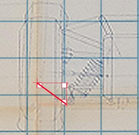
You mention that the gearbox input shaft will not engage in the crank. Transverse engines do not generally engage in the crank like inline set ups and there is no bearing nosing machined on the end of the gearbox input/drive shaft. See photo.
A bit quiet on here for a while. I've been messing with my adaptor plate for a few weeks. Using the one I'd had made I've started on work my own.Taking the measurements I've had one machined in hard clear acrylic and by using a centre machined to fit the crank it fitted onto the v6 perfectly.
Then by fitting the centre to the mr2 gearbox input shaft I've offered it up to the gearbox and aligned the two.Unfortunately one of the 2 bolts/dowels that align the adaptor plate to the v6 engine (used to align the gearbox usually) collides with the output cover plate on the gearbox. Also 3 of the 7 bolts on the cover plate will bind also. So this got me thinking!!
First up I removed the cover plate on the mr2 gearbox to have a look. My luck was in as it's just a flat 10mm alley plate so I can change the 3 offending bolts to either countersunk bolts or cap head bolts and counter bore the plate.To over come the alignment dowel I'm going to have to increase the thickness of the adaptor plate from 10mm to 20mm. Because of this I'm going to switch from steel to aluminium for the plate.
Now where the gearbox cover fits I'll remove 10mm of metal from the plate so keeping both alignment dowels in the plate. I can also remove some metal so I only have to counterbore one hole for the bolts.
Before I have the final plate made in alley I'm have another one machine in hard acrylic to check everything fits.
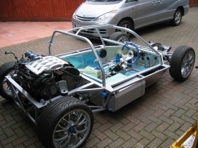
Been looking at various chassis and designs I've come across a dax cobra one. some on here have a said a basic platform type chassis are not ideal but this gets good reviews and the cobra boys use big powered v8's. I also like the front camber compensation idea.
Had a look at this build. The chassis uses a De dion type rear setup with trailing rear arms. In the photo the engine and box sit quite high and he mentions this in his notes and how he has lowered it in the chassis to get the drive shafts more horizontal.
This got me thinking. A car I have followed over the years was the phantom gt which became the vortex gt. The designer called it a modern day dino!! So I've posted on there for spec's etc and to see if their chassis could be used of can be altered and used.
Been looking at various chassis and designs I've come across a dax cobra one. some on here have a said a basic platform type chassis are not ideal but this gets good reviews and the cobra boys use big powered v8's. I also like the front camber compensation idea.
ian
But the engines in the wrong end! Why not look at a Pie Valley chassis?
Yes the dax chassis would have the engine the 'wrong end'. It was just an example of a simple ladder type chassis similar to the dino one. What I liked was dax's camber compensation arrangement at the front instead of an anti roll bar.
The other chassis with the 'engine the right' end was from a vortex. I was mulling over adapting one of these as I know where there is one for sale.
I had looked at pie valley chassis's after they were featured in which kit magazine but they use either beetle donor parts or mg and neither fits in with my design.
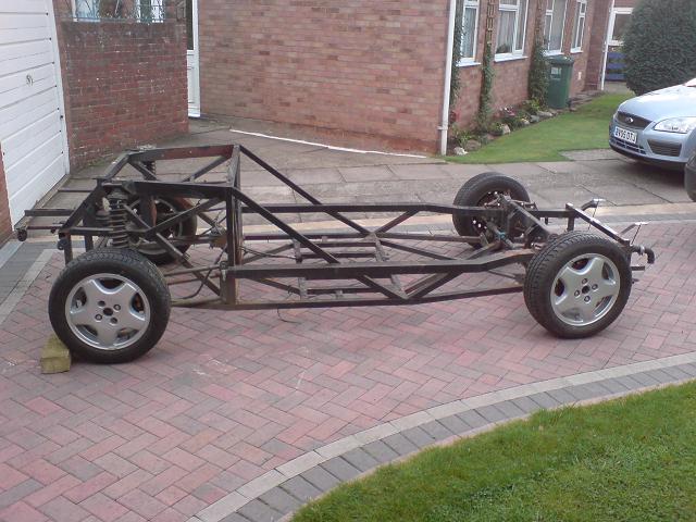
The original chassis I have is built from small 25 x 25 and 40 x 40 box section with 1mm flat plate. It has high cills and a huge centre /back bone which I want to remove as I want a more authentic cockpit. see attached
Hi Ian,
that looks like the original John Hurst (DGT / Deon) chassis to me. My guess would be that unless custom axles were specced it would have the same rear track as the front track of the donor Lancia Beta. One site I googled put that at 1410mm front Beta Coupe track - pretty close to a genuine Dino.
As for removing the central tunnel - my uneducated guess would be that you'd have to compensate with other high beams or beef up the beam's section at low level. I've been thinking of three longitudinal 25x25mm rails. Two as high and wide as possible under the top of the sill and one as low as possible. short upright tubes join all three with triangulation in all planes.
and here's a genuine 206GT - see how broad and high the sills are
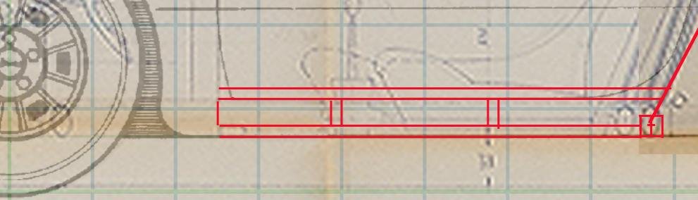
The chassis rails on the dino are oval shaped and at the tallest are 75mm or 3 inches high by 40mm or 1.5 inches.
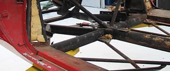
The deon uses very small 40mm x 20mm tubes for perimeter of the centre section beef up with 1mm steel sheet for the cills. This then has a small 20mm x 20mm sq tube top rail welded to it. It is sparsely with more braced with 20mm x 20mm sq tube.
The centre tunnel is again 40mm x 20mm tube beefed up with 1mm steel sheet and 20mm x 20mm steel tube along its top edge.
My Idea is to use 75mm x50mm tube for the perimeter with 2 x 50mm x 25mm rails for the centre tunnel.I will weld in cross bracing into the floor with additional steel to bolt in the seats and seat belt anchors.
Deon used 40mm x 40mm for the rear/engine section and I'll copy this with the same. The front section used a mix of 50mm x 20mm / 40mm x 40mm / 20mm x 20mm. I'll probably use 40mm x 40mm and cross brace with 25mm x 25mm.
I've attached a few more photo's showing how little the deon centre section has cross bracing.I've also tried to show how small some of the rails are.
Hi Ian,
that looks like the original John Hurst (DGT / Deon) chassis to me. My guess would be that unless custom axles were specced it would have the same rear track as the front track of the donor Lancia Beta. One site I googled put that at 1410mm front Beta Coupe track - pretty close to a genuine Dino.
As for removing the central tunnel - my uneducated guess would be that you'd have to compensate with other high beams or beef up the beam's section at low level. I've been thinking of three longitudinal 25x25mm rails. Two as high and wide as possible under the top of the sill and one as low as possible. short upright tubes join all three with triangulation in all planes.
and here's a genuine 206GT - see how broad and high the sills are
cheers
Ross (in NZ)
Yes Ross that is a deon gt chassis. It was just to show the tubes they used.
ian
Hi Ian, the route of putting in larger section tubes and plate strengthening is very sound and of course there is the option of increasing the gauge of the steel as well. It does make for extra weight but its a pretty light car anyway. When I said 'how broad and high the sills are' I was meaning that within the body lines of the sill there is room for a differently-shaped and stronger chassis side member than the Deon has. It relies on height over the original Ferrari chassis's 3" oval tube. I'm following your build avidly
cheers
Ross
Attached are a few measurements of the deon cockpit to show just how high the centre tunnel and cills are.
The centre tunnel carries two coolant pipes to the front mounted radiator/brake pipes and several wires. It's far oversized for this.
The high cills also ruin the look of the cockpit. My car also has the later type lower floor said to give more room,but resulted in deon removing alot of the cross bracing to allow for it.
ian