This is a read-only archive of the old Madabout Kitcars forum. New posts and replies are no longer possible, but every thread is still here to browse and read.
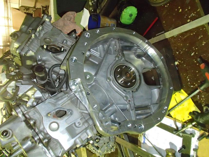
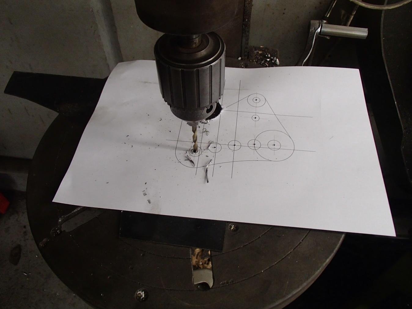
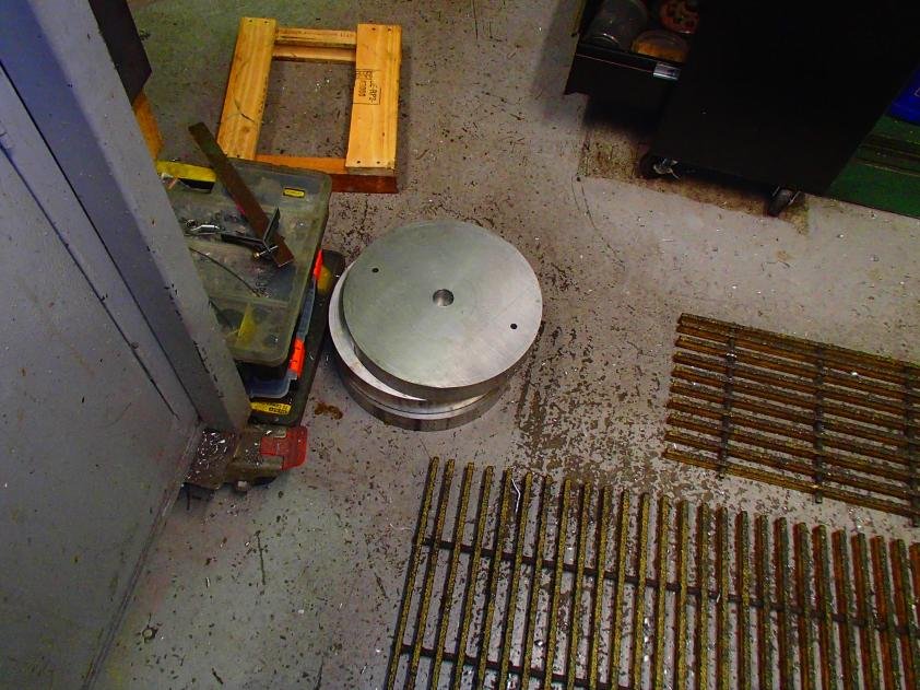
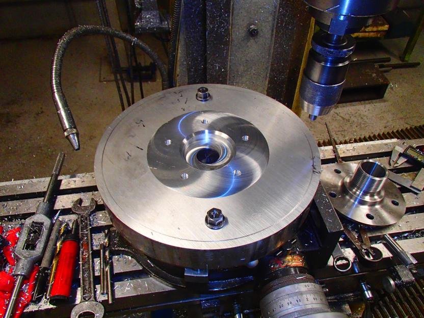
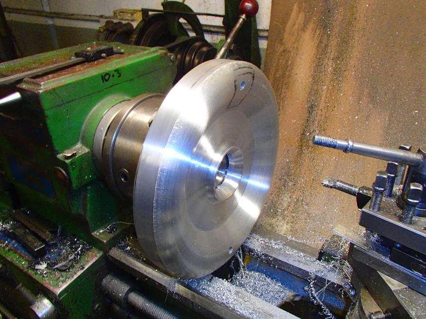
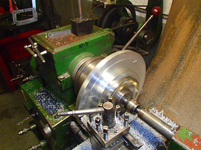
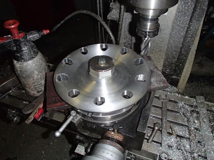
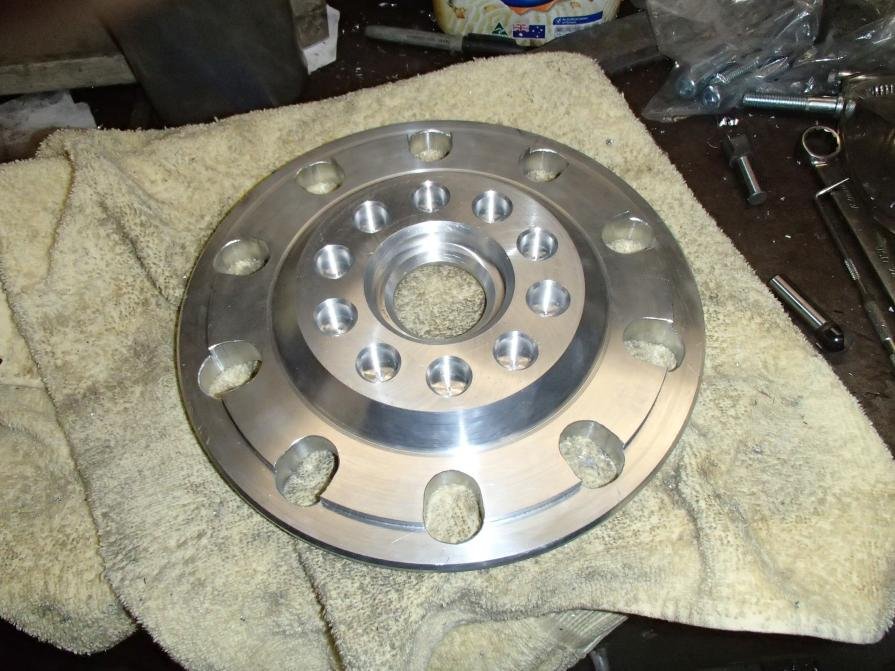
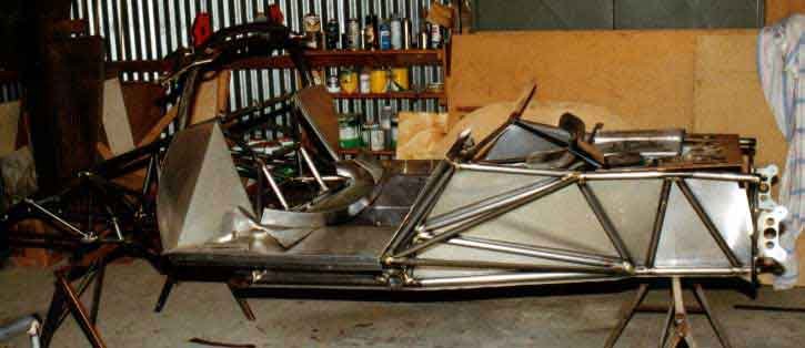
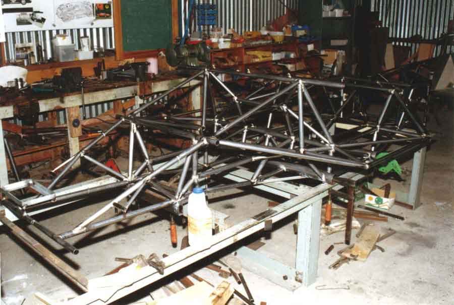
After making the rear frame I needed to finalize the engine location so I made the conversion plate.
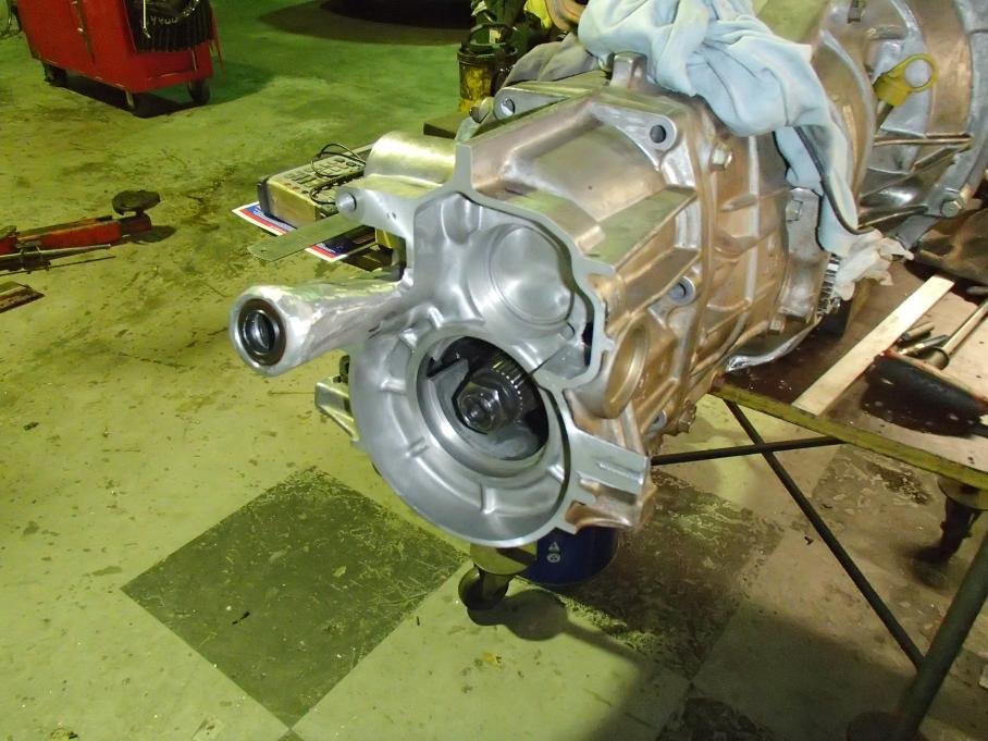
I opted to use a Subaru 5 speed transaxle modified to drive out of the front diff only.
I measured the dowls on the Subaru box and Nissan engine.
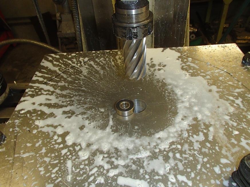
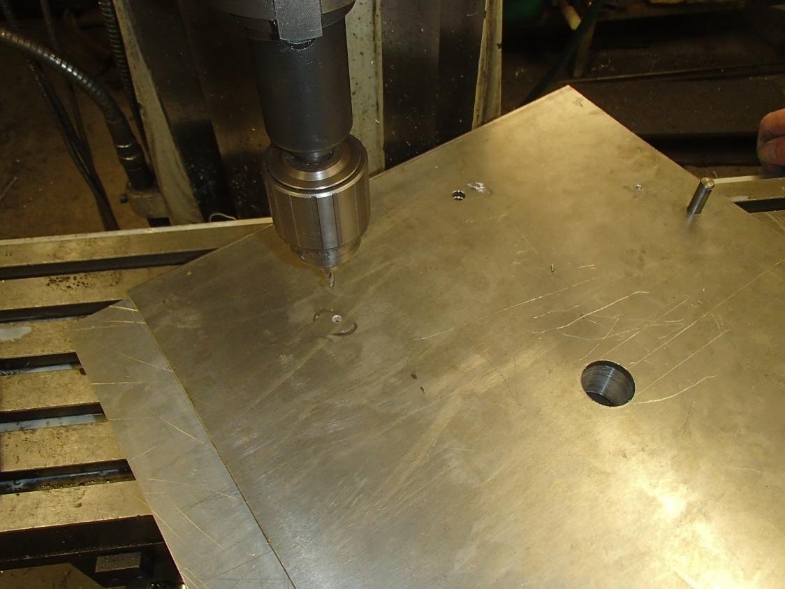
Machining a 32mm hole in the centre allows me to put a spigot bearing in then after drilling the dowls I can drop the box on and check it fits.
The rest of the plate holes are transfer punched, scribe and cut on the band saw, then linished.
The inner hole I used a pattern fixed to the plate then ran around the inside with a router.
When The engine comes out the plate will be heavily drilled out to reduce the weight
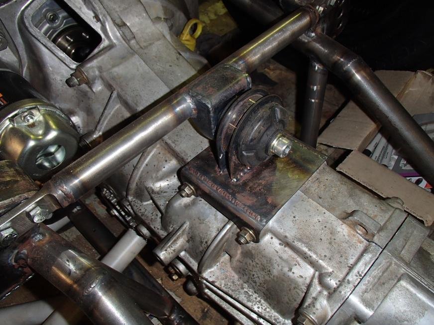
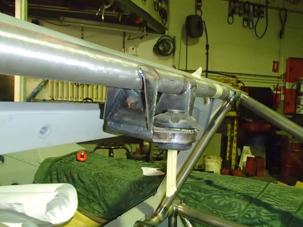
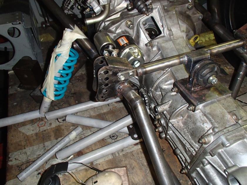
Engine and suspension mounts.
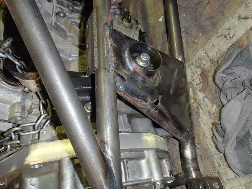
I use a suspension bush for the mounts, I used them on my GT40 and they cost $24 and they last.
The bush presses into the cup that I machined out of a bar,it has a 2mm wall.
The brackets mounted on the block are sheet steel 3mm base plate and 2mm bracket.
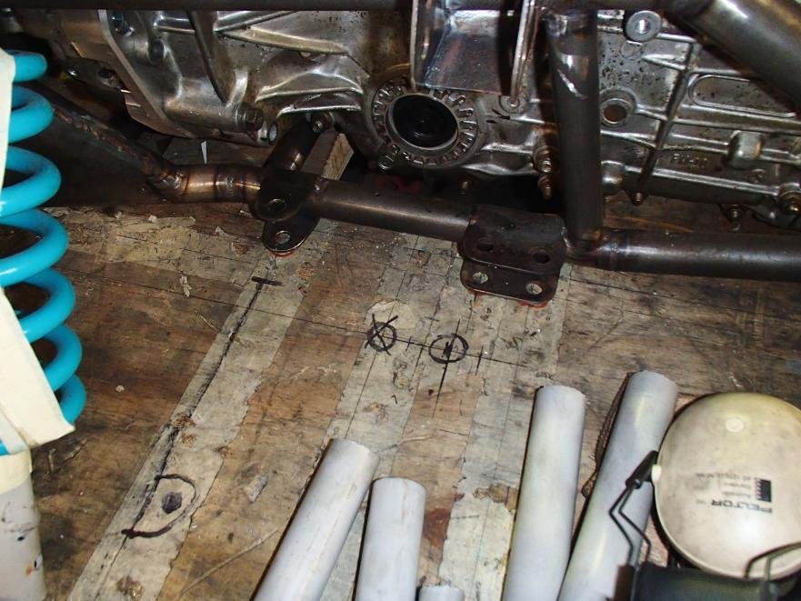
The engine has 4 mounts in total, the gearbox mount is part of the rear crossmember.
The upper lateral link is made with adjustments for rear roll center.
This is the advantage of using a cad system when it comes to making one off brackets.
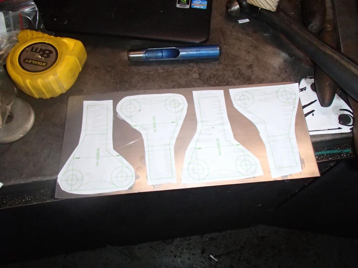
I print on a4 to scale then spray glue and attach to the sheet metal, all the cutting drilling is done then peel it off.
Gearbox
EBAY $250
Subaru 2.5 lt turbo liberty 5speed.
I removed the extension housing ,rear diff ,transfer gears and filed them in the bin .
The center housing I have left the shift casting and machined off that that is not required.
The bearing hole I will plug, I can buy a splined sleeve that go's onto the lower shaft and this will make it drive out of the front diff.
The rear I have made a sheet cover that will get 2 m6 bolts and some sealer adhesive.
The diff I will weld the center as it will be track only.
In an earlier post I made sheet metal uprights.
The rear I was happy with but the front I never was.
I could also see issues fitting the steering arm.
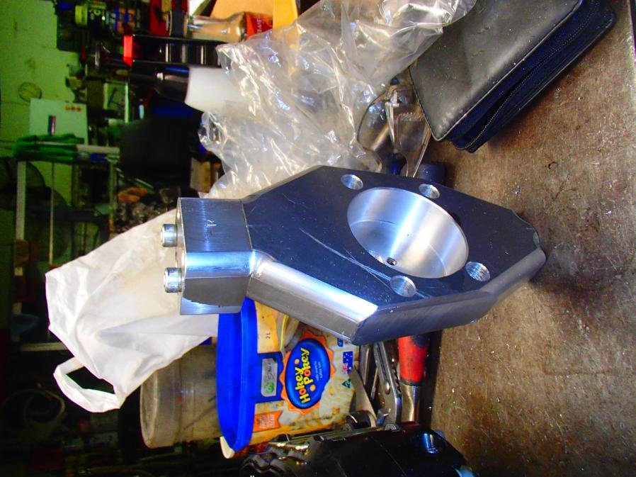
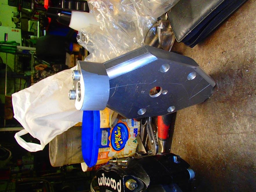
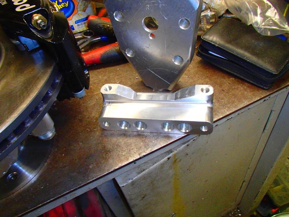
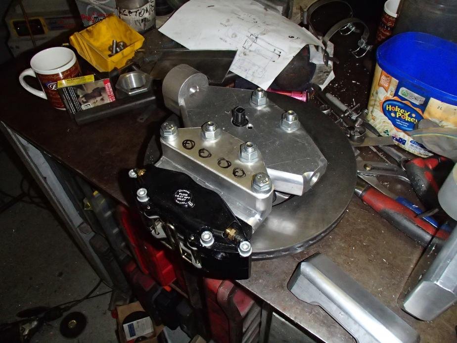
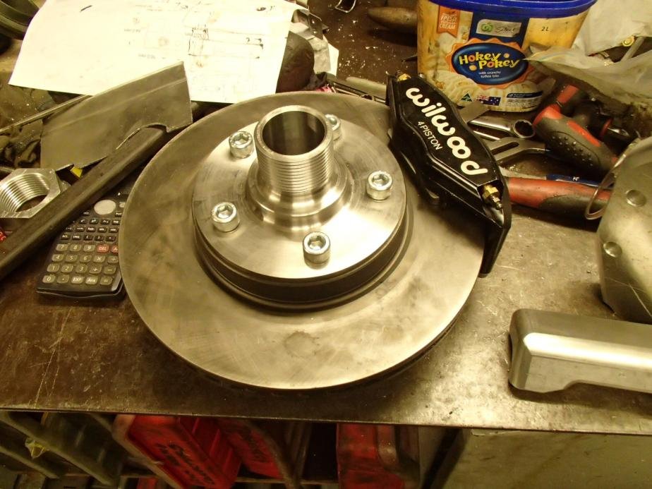
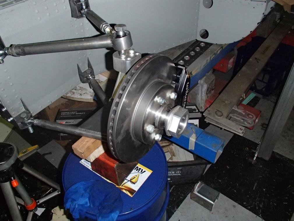
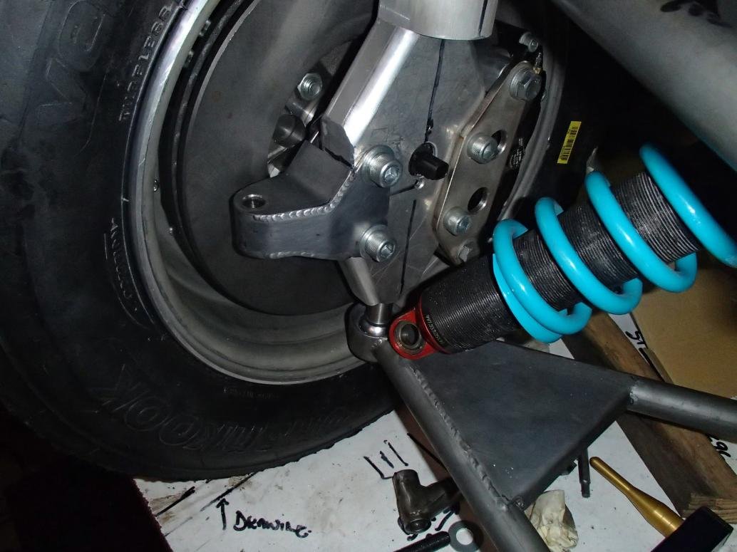
With the scrap from the center of the gearbox conversion plate I made 2 front uprights and I had to make caliper brackets as well.
The uprights are 5083 and the brackets are 6061 t6 .
The caliper has a S/Steel bracket to hold it to the upright,as per the sheet pattern in pic 4.
The steering arm will be sheet ,one in between the top ball joint mount and one on top.
All the radius on the edges of the uprights I did in the mill just using router bits (tungsten carbide).
I mount it to an arbor then do all the profiling on the front.
I then turn the arbor around and remount and do all the rear face.
Cutting the slots is about a 6 step process due to the shape.
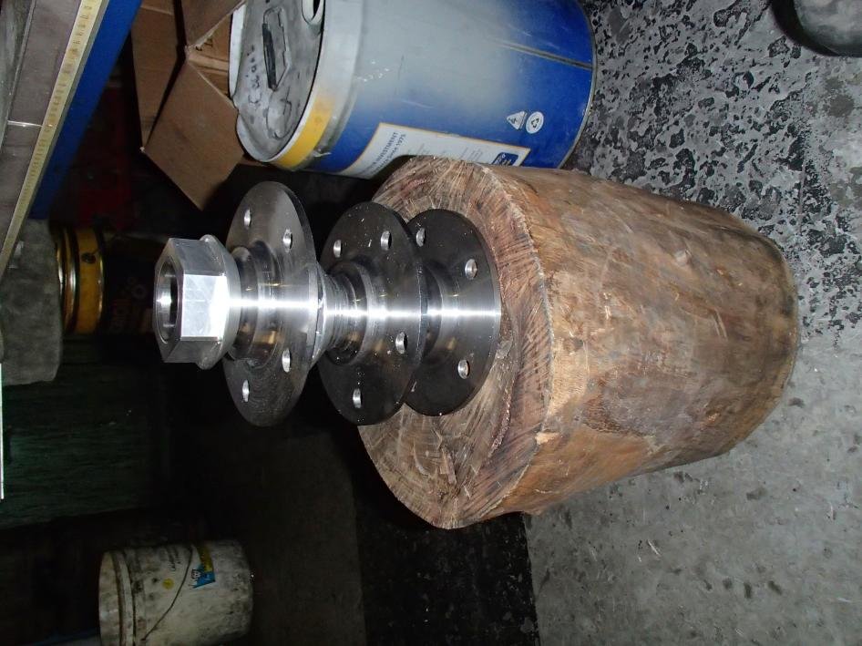
The wheel and rim is 5kg.
All 4 uprights are assembled, the metal spinners will have the rim half's done next week, the Cr moly turns up Monday for all the suspension , the rack I have finalized and will order Monday.
With in a month I expect to have a rolling chassis.
Does not feel like a lot considering the time that has lapsed but a lot of things came up over the last few months and it took me away from this project.
Over the last few weeks I got some done on the suspension.
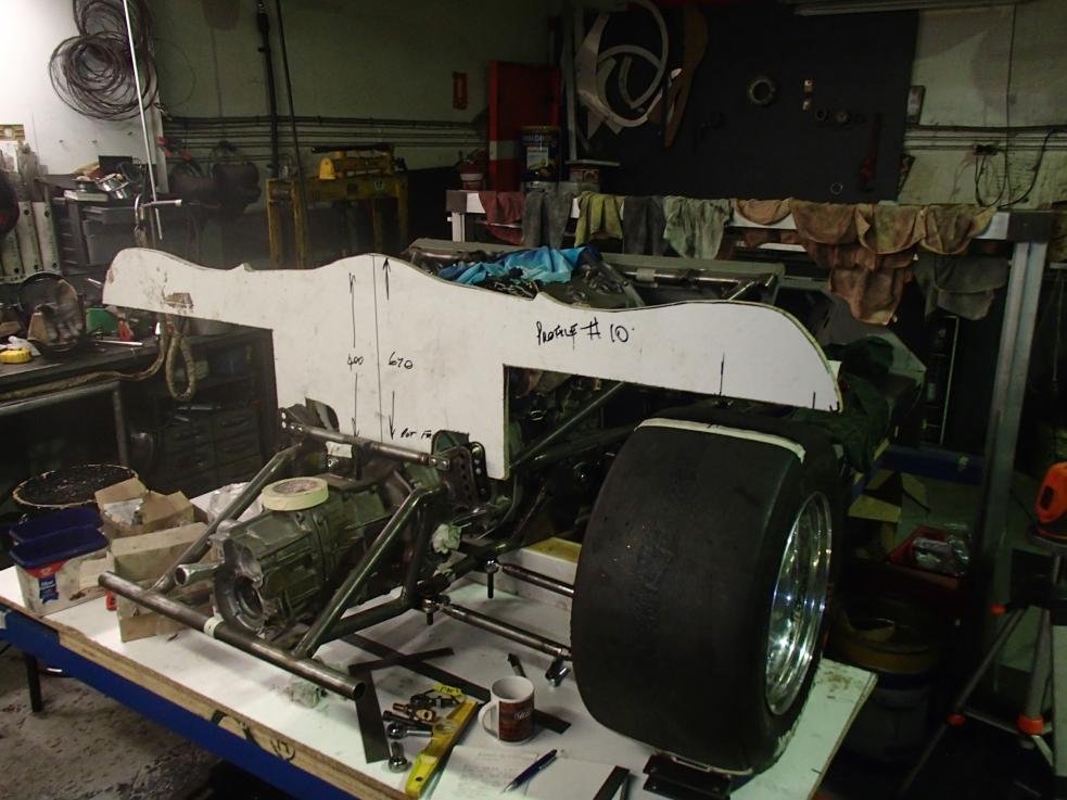
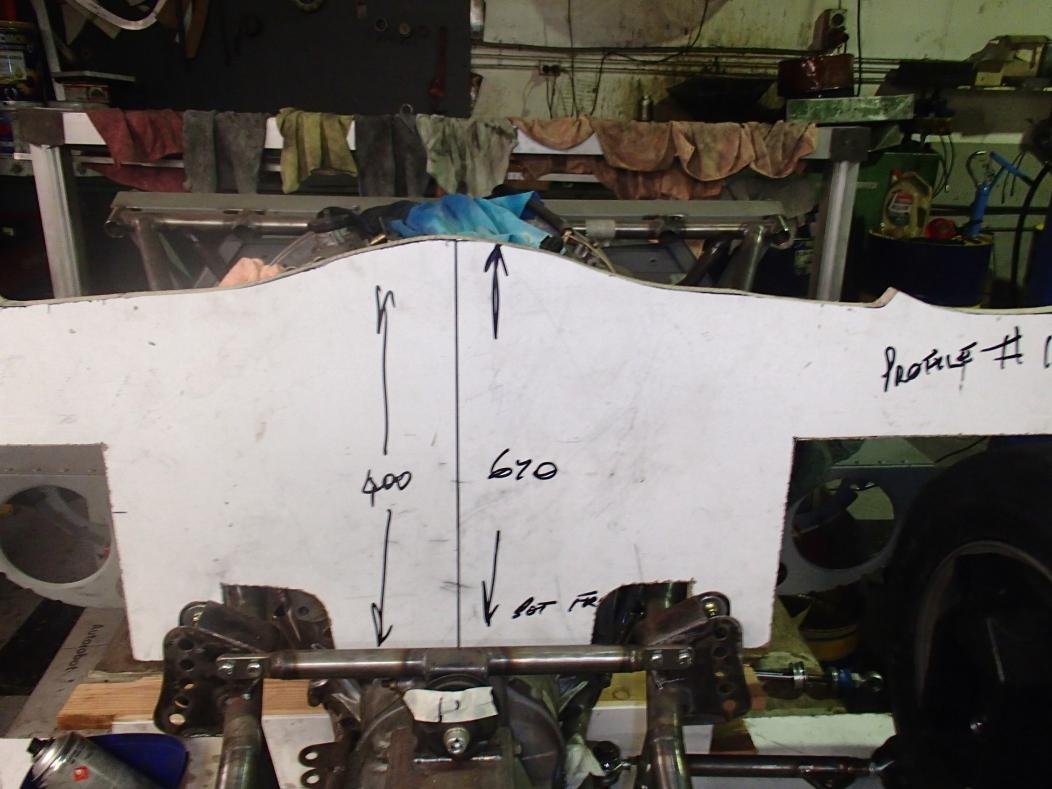
The first thing made was the body profiles that sit directly above the axle lines.
This is so I make sure I am building under the body work..
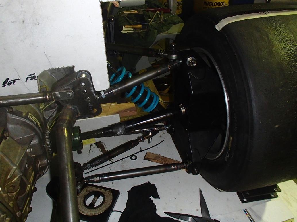
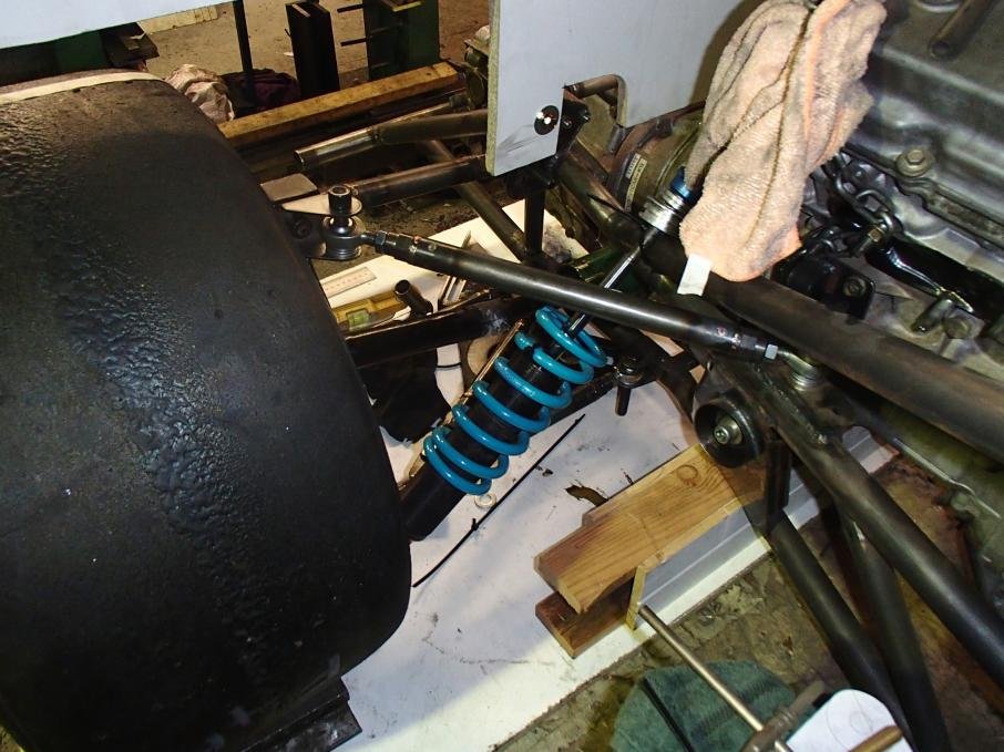
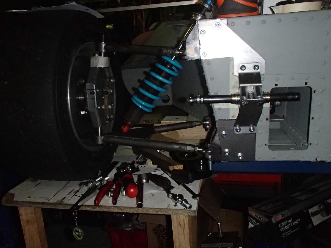
I placed the wheel and Tyre in the location and just start making links.
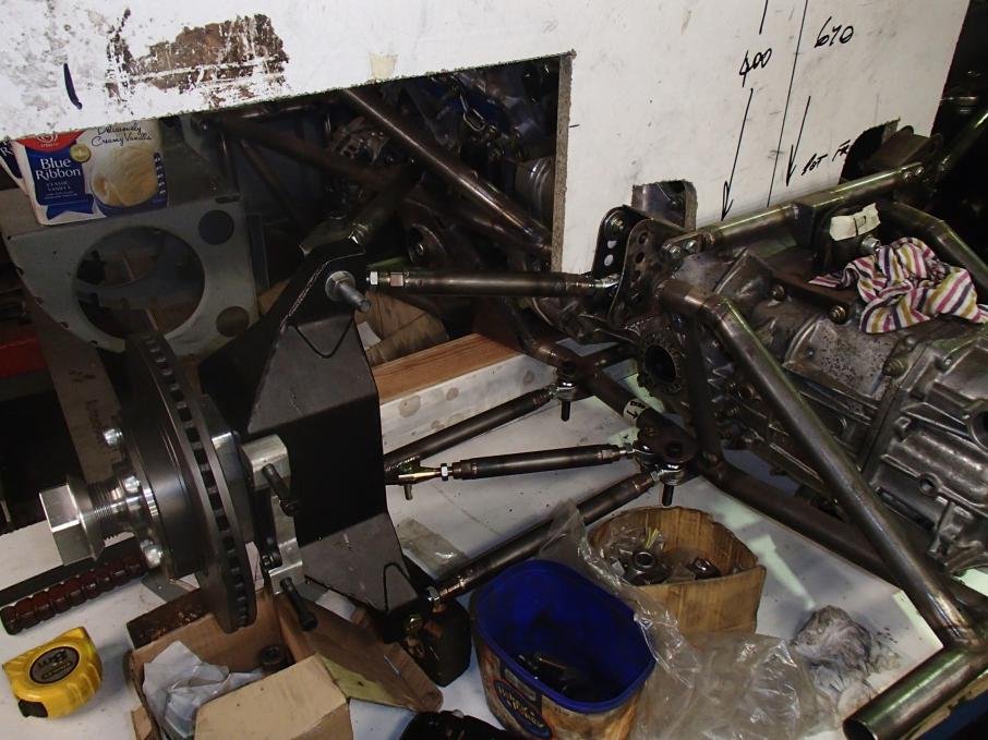
I have 2 lower laterals with a diagonal.
I upper lat and a trailing link.
The original cars had very much a gt40 set up with long trailing links. I want to get away from that for packaging reasons.
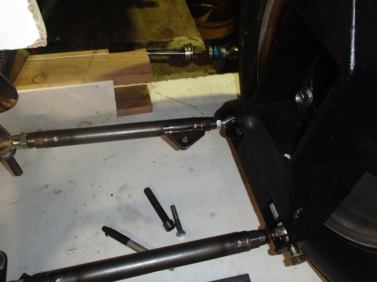
The front I wanted removable brackets so that I have the flexibility to change roll centers further than the bracket allows by replacing it with another.
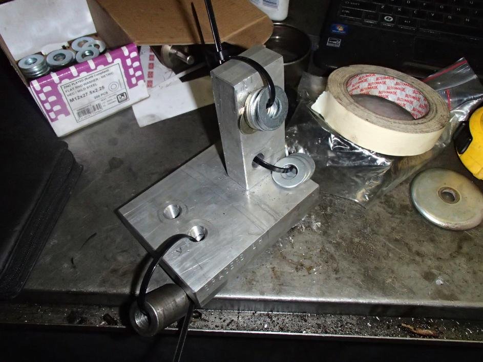
The lower arm inner joints are a fixed position, they go into a very simple jig which is a piece of ply with 3 holes drilled in the correct location to get the location of the 3 joints the same left and right.
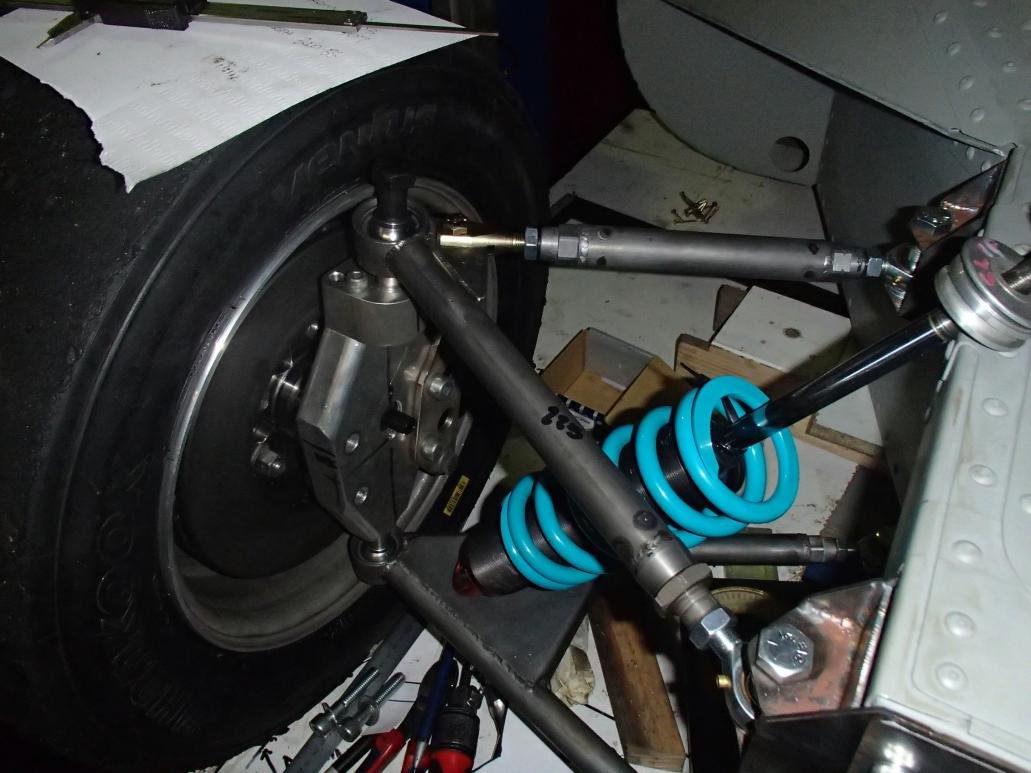
The upper and lower sphericals are both 5/8 the housings I machined, all the left and right 1/2 rose joint adjusters I also machined.
The machined parts and tube work is all 4130 crome moly.
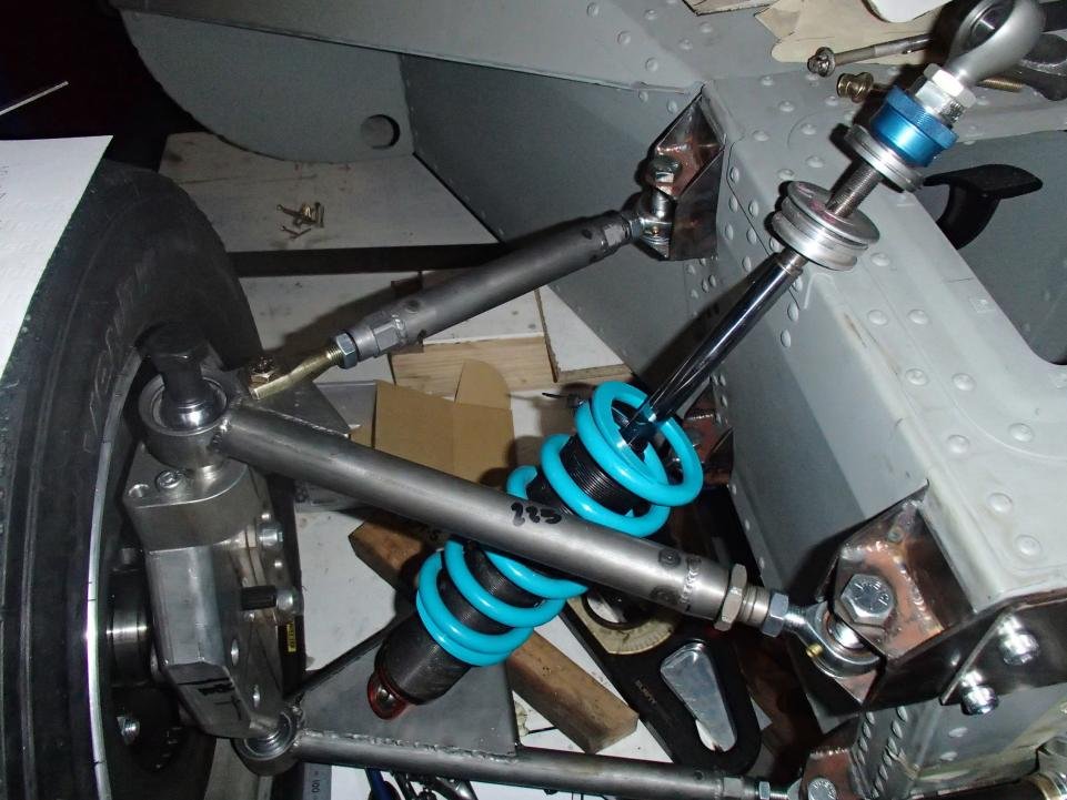
the upper arm is split with a clevis.
All the camber caster is adjusted off the top arm.
Again brackets are removable and bolts pass in the vertical direction.
The reason for this was mainly to keep the joints in compression and contraction when loaded.
The front upper joint is in a fitting that has an outer L/H thread and a 1/2" inner R/H thread.
By rotating the threaded sleeve (the part the rose joint is screwed into) I can adjust without removing the bolt out of the upper inner joint.
The steering arm is crome moly sheet.
I printed out the panels and glued to the sheet then cut to get them all the same.
I had worked out through susprog 3 where the arm needed to be.
I then freehanded the first one at the correct location.
I then made a jig that it fitted into but mirrored the hole location when in the mill.
The parts are all assembled and welded in the jig and this gives me a mirrored part.
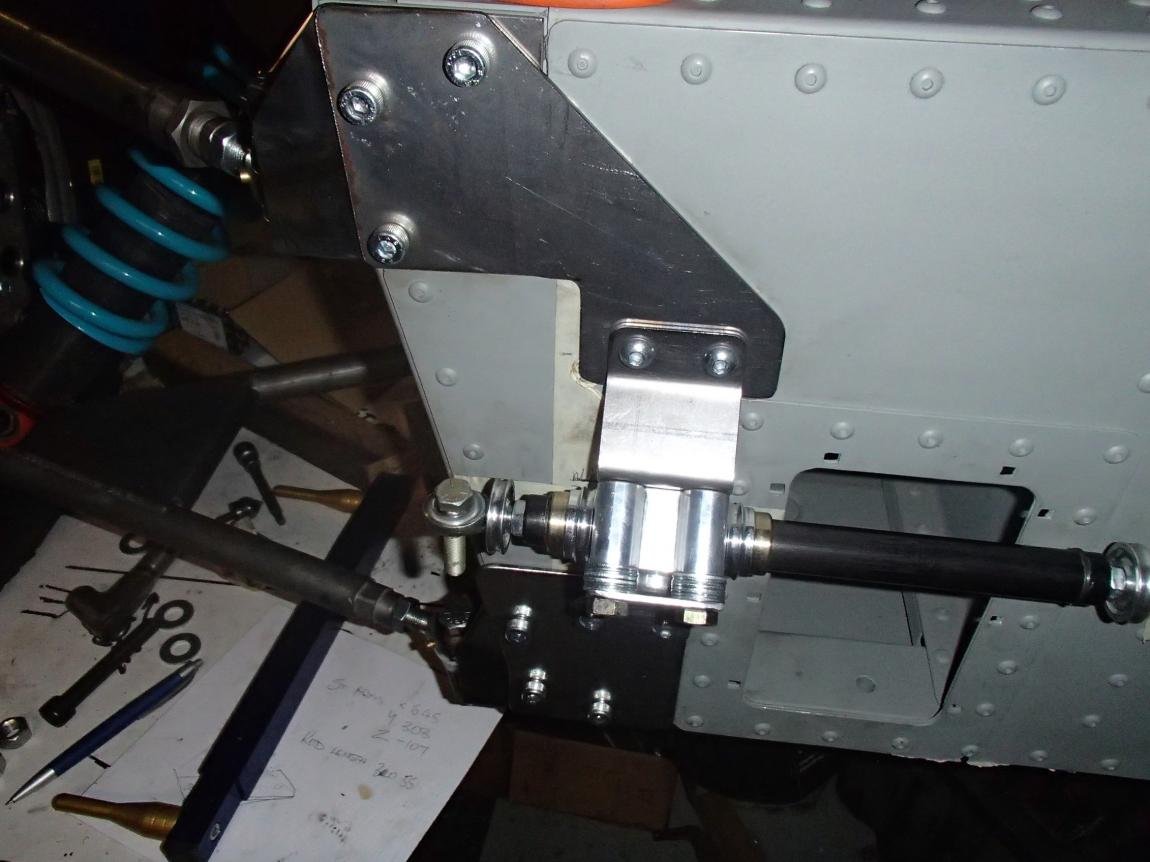
steering rack I decided on Strange engineering 12:1 ,they use them in sand buggy's and drag rails.
I will be extending the end by using a linier pillow block 106mm long mounted to the front .the rack will have some form of link to a hardened shaft 20mm dia.
The brackets the rack is mounted to will get flanges attached to up the rigidity,I have not done this before so I will have to work out the bugs.
I dont want to make a rack specific to this car.