MadaboutKitcars

This is a read-only archive of the old Madabout Kitcars forum. New posts and replies are no longer possible, but every thread is still here to browse and read.

New Cordite Build, with a twist....

4 Jul 2014, 7:07am
Mac - Looks like it is really coming together nicely now. :cool:

Viatron wrote:
...I have gone through the gel coat in a couple of places but there is plenty of glass underneath and as I'm etch priming first I'm leaving them as is they look rough but in fact running a hand over the patches are dead smooth ...


This also gives me hope, as I've already gone through the gel coat without fully removing the flash lines. :rolleyes:

I also plan to add some extra fibre glass on the inside of the shell to beef up some areas.

Good luck, Paul. :)
4 Jul 2014, 9:23pm
A few hours up the lair again this afternoon and in fact got in trouble with SWMBO as I wasn't back until 21:30! lost track of time as I was on a roll, more of that later.
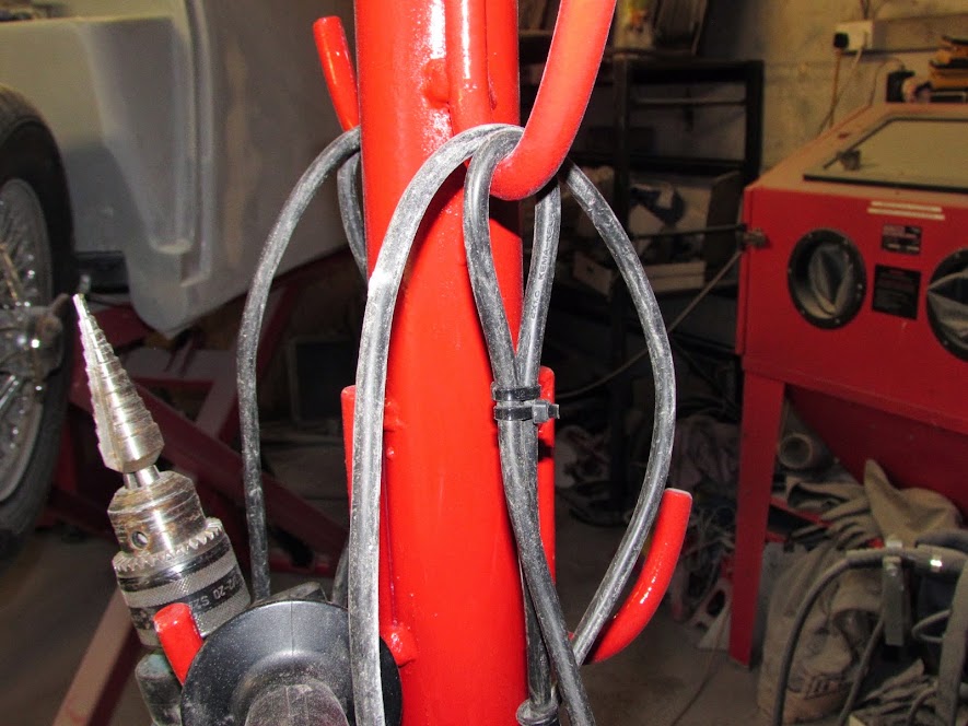
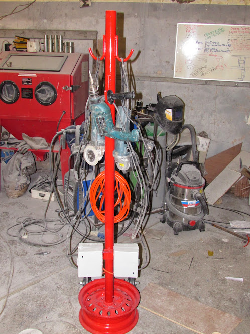
First order of business was to finish the Grinder Tree as my RBD protected waterproof double sockets , cable etc had arrived. About 45 minutes had it all finished, just need to extend the mains cables on the power tools which ill probably do tomorrow if I remember to take my soldering iron up to the unit.


A simple loop in the cable allows the tools that don't have a suitable hole to hang from to be hung.


and Ta Da!


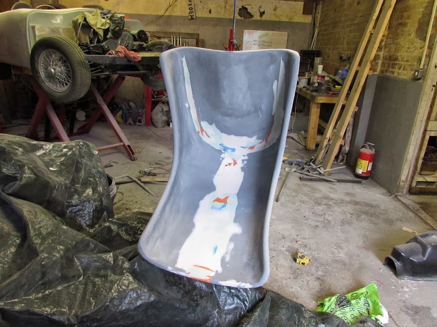
Flushed with success early on in the day I set too on the seat buck and about an hour of sanding down filler and flatting the whole thing back with 150 grit saw it ready for paint.


Luckily I had half a can of etch primer handy as I really didn't want to break out the spray gun just for the seat.


Couple of small runs but nothing that wont flat out tomorrow.


Looking through the odds and ends of paint I still have about half a litre of the epoxy primer that was used over the galv on the chassis, as these are going to be covered I don't need a mirror finish on the gel so I think a couple of coats of that then a good 3 or 4 coats of wax will suffice to take a reasonable mould from.

So far 2 things have gone to plan today, it cant last....... stay tuned for part 2!
4 Jul 2014, 9:43pm
Part Deux

So finally with 2 successful sub projects done I decided it was time to attack the lighting plinths on the rear of the body, a job that to be honest I have spent far too much time thinking about and not enough time doing!

Stage 1, tape up a light unit so it doesn't get covered in filler!


stage 2

Decide on the position and orientation, I faffed for a good 30 minutes but decided on this:


Which meant I had quite a large area to build up!


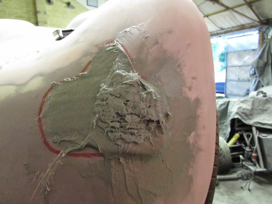
So marked out the outline


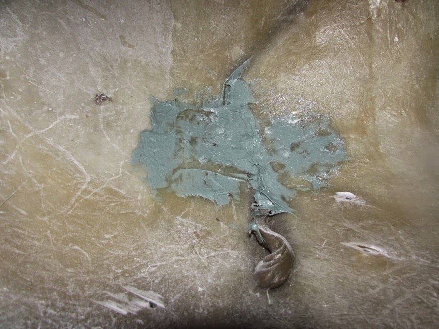
I am conscious that this is going to be a reasonable size lump and to help key it to the body I drill some holes through so that the initial layer of fibreglass bog has something to key into.


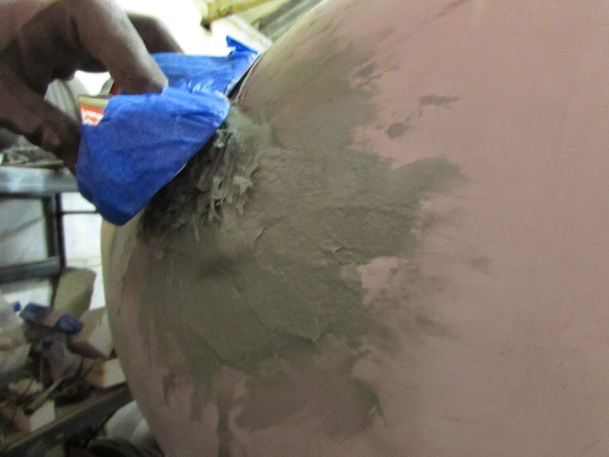
First coat looks absolutely horrendous but working on a vertical surface isn't easy! its got to look worse before it starts to look better!


When I did this first layer I made sure that a fair amount was squeezed through the holes in the body and then smeared the excess around o the back of the panel to lock it all in.


Still a ways to go!


but a few more layers and a bit of profiling with a sharp knife when it was still green plus some rough sanding and it started to take shape.


Constantly holding the light unit up to the body and using a read marker to remind me of where I needed to build up helped.


in between trimming and sanding it still looks horrible!


Slowly but surely it started to look like the picture I had in my head....amazingly!


And the light unit was even starting to fit!


Nearly there now....


and all of a sudden the light unit fitted and the basic shape was done, and very solid it is as well.


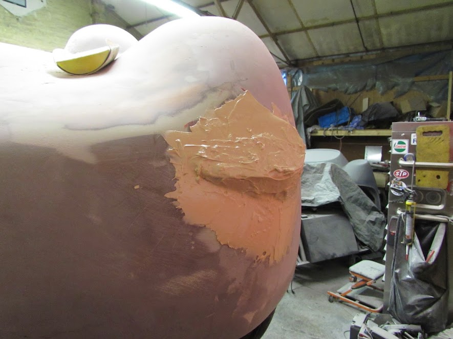
One disadvantage of the really good surfacing filler I have been using is its as runny as my nose without hay fever meds! so very difficult to use on a vertical panel but managed to get a first coat on and I reckon it'll only take 20 minutes or so of sanding in the morning to have it looking pretty ok.


so check back in around 10:30 in the morning and ill post a picture of it post first sanding!

All in all a good day. hope tomorrow is as good. I have Dave and my mate Sean coming up tomorrow to lend a hand as were hoping to get the bonnet sort of on and trimmed and many hands will help.

TTFN

Mac
5 Jul 2014, 7:17am
Mac - Your tool tree is a great idea and I love how you just "knocked together". :cool:

Can I ask a question about the mounting you made for your rear lights?

Viatron wrote:
... the basic shape was done, and very solid it is as well ...


Is there a limit to how think this filler can be?

Thanks for the "drilling holes" tip to help it stick to both sides as it were.

And finally good luck with your plans for today...

Viatron wrote:
... get the bonnet sort of on and trimmed ...


Based on the messing about I was doing yesterday, I can't wait to see how it should be done.

Cheers, Paul. :)
5 Jul 2014, 7:31am
Paul I think the thickness I have had to use is probably close to the limit I would be happy with. Drilling they key holes was important as without it I would have always had a nagging doubt. In addition to the holes the area was prepped with 80 grit before I started and then wiped down with thinners to a point where the surface became slightly tacky. All these steps means it is for all intents and purposes part of the body not just an added lump.
The other thing you have to carefull of is thermal runaway. Once I had built it up 3 layers thick I had to wait about 30 minutes as the heat that built up was getting a bit too warm.

Ttfn
Mac
5 Jul 2014, 8:55am
Quick flat back:


just filled the marked areas hopefully this will complete the shaping and then just need to get the finish right.
5 Jul 2014, 5:12pm
so onto the main event, today was nominated as bonnet fitting day as there were 3 of use up the youth (ish) club!

Plonked it on to get an idea of where to start.


we needed some way to set a datum to measure from on the body, Sean (in the background of the previous shot) had a moment of clarity and thus was born the transferring measurement from tub flange to body thingy!

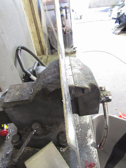
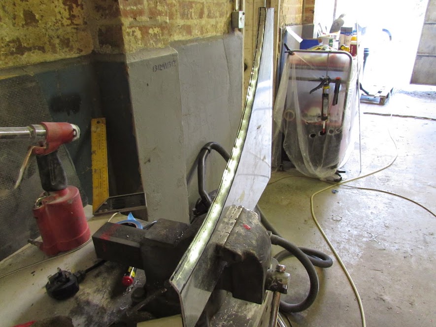
Take one piece of 2mm Ali strip and cut to a random length and trim corners at one end thus:


Insert into vice and ben a 90 degree (ish) angle on the end that the corners have been cut at.


Next drill a hole at a random distance from the end just big enough to take the trusty red whiteboard marker:


Jam the marker pen into the hole


You now have a neat little device that slides along the front of the bulkhead and allows you to transfer a relatively accurate line rearward on the body at a constant distance from the bulkhead flange (FLANGE! FNARRR FNARR)


by sliding the tool along the bulkhead we managed to get a good datum to do the bonnet trim from.


Once the line was done we using thin red gaffer tape to give us a more accurate line to work from.

Measuring at approx. 4 inch intervals we confirmed that the magic number was 78mm...

next we got the bonnet into what looked like the best position and fixed the bottom rear at both sides with a self taper.
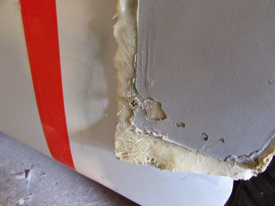


We did try using a tape measure but came to the conclusion that we would be there all day and the best policy was to pick what looked right and run with it, remember the bonnet is still from the original Sammio moulds so I wasn't expecting great things...

With a trolley jack supporting the front in a position hat looked ok I then marked the cut line by simply making a mark every 2 inches 78mm from the front of the tape line on the body.

The dots were then joined using more red gaffer tap and checked again to make sure the distance was a consistent 78mm.


One quick cutting wheel session later and tada!
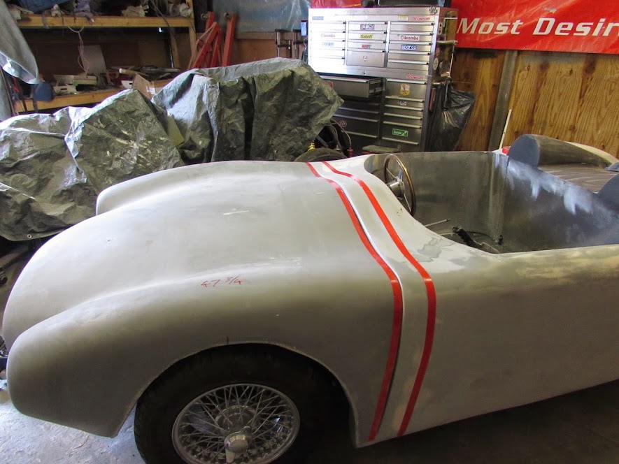


The panel gap is still a little wide in places because the transfer tool was running at the bottom of the bulkhead flange and its not quite 90 degrees in places but nothing a small skim of fiberglass filler wont cure.


To support the bonnet whilst refining the alignment we taped some 10mm electrical flex in place to sort of simulate the rubber seal that will eventually live there.


and there it is...


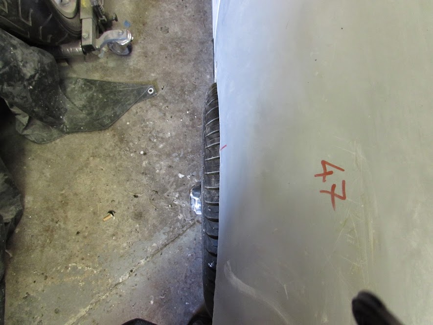
Couple of issues cam to light during the fitting, the alignment in the arch of the drivers side wheel was fine although the arch itself needs work to actually make it even vaguely round:
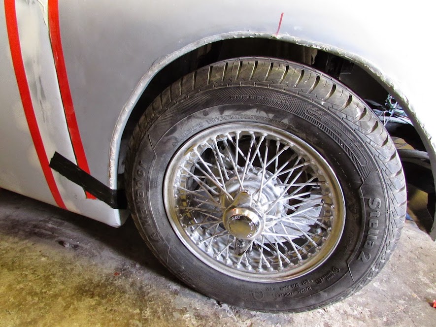


Passenger side though has the arch way too far back, the tyre almost touches at the front.


This shot of the front looks like the bonnet is too far down on the right when you compare it with the front of the chassis visible in the nose opening but its just an optical illusion its actually pretty parallel.
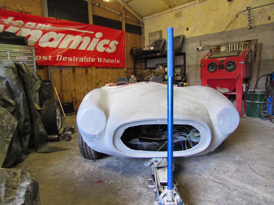


but check out the area between the inside edge of both hand lamp mounting flats and the outside edge of the projecting bonnet opening! The gap on the right is about an inch and on the left its nearly nothing.

Ill go into measurement's on a separate post but its not pretty, not surprised Gary sold up when he did, if he had sold many more of these I reckon there may have been a lynch mob at his door! Other curious include differing distance from the back of the bonnet to the top of each headlamp mounting surface, if you fitted a headlamp to the drivers side all you would see in the dark would be clouds etc etc etc. A bigger problem that I didn't get a shot of was that the drivers side tyre sticks out beyond the wheel arch by about an inch. grrrrrr

Since the bonnet was border line as a bonnet I decided to use it as a white board instead.


Sounds bad but all in all I'm happy with the way today went at least the bonnet is trimmed and on, just need to keep my head down and get on with it. Watch this space for bonnet butchery in the next week or so!

TTFN

Mac
5 Jul 2014, 6:48pm
Mac - Thanks for the step by step guide, it is a big help. :cool:

Can I just check that when you screw the bottom of the bonnet into place, the rest of the bonnet is sitting on top of the body shell.

I look forward to seeing how you hinge the bonnet & "adjust" the arches.

Good luck, Paul. :)
5 Jul 2014, 6:53pm
Yep screwed into the body behind where the cut is going to be made it meant drilling a hole in my freshly prepped tub but it was a necessary evil to get the position locked in and will only require a dap of filler afterwards.
Just ordered the 19mm hydraulic tube for the tilt frame, have used this stuff in the past and it welds nicely and is just a little softer than plain steel tube so bends easier.

TTFN
Mac
7 Jul 2014, 4:17pm
Mac - I posted the first part of my bonnet review on my build thread.

I still have a few photos to take, but rain stopped play.

Good luck, Paul. :)
7 Jul 2014, 5:54pm
cheers mate off to have a look now...
8 Jul 2014, 1:01pm
I've just posted the final round of bonnet photos for you in my build thread.

Good luck, Paul. :)
8 Jul 2014, 8:16pm
So todays task up the crèche was to try and formulate a plan for the bonnet that didn't involve making one from scratch as the one I have sort of fits if your blind and viewing it in the dark. Decided I needed first to establish a datum to measure from so picked up a laser light thingy:


This allowed me to throw a line from the back of the car ensuring it passed exactly down the centre of the chassis by measuring in from either side of the centre chassis rails to find the mid point onto the dash and through onto the bonnet.


One I had established the centre point I marked it with tape. The centreline is the right hand edge of the tape in this pic:


a bit of ruler and tape measuring gave me some basic, but disturbing dimensions.


In the above pic you also get some idea of how much the drivers side wheel projects out from the arch but to clarify, here is the passenger side:


And the drivers side:


And if you don't think it looks that bad try this:
Passenger side


and Drivers side:


So a bit of a problem.

Next Problem are is the gap between the nose projection and the headlamp rims.
Drivers Side:


And Passenger Side:


To be honest this is annoying but I can probably disguise most of it with some judicious filler work but the drivers side tyre projection is a show stopper as not even my friendly MOT man would let this pass.
And the measurement on these pics show how this has occurred, measurement are from the centreline to the outer edge of the wheel arch:

And


So the drivers side of the bonnet seams to be approx. 80mm or approx. Now this seemed far too much so as an exercise I halved the difference and put in a temporary new centreline thus (the right hand shorter piece of tape is the theoretical centre of the bonnet forgetting the original laser line. (Now edited as just realised I can't count!)


But its plane to see that that just looks plane wrong...


You can just see a small marker line between the 2 tape lines above the nose projection, that's the centre of the grill orifice.

Confused, yeah me too.

So I am guessing that the real centreline seems to be somewhere between the right hand piece of tape and the small marker line. At this point I curled up in a corner and sucked my thumb and cried for my mummy.....
8 Jul 2014, 8:46pm
Is it worth buying a new front end... one way to disguise the perculiarities once finished would be a racing stripe (offset).
8 Jul 2014, 8:46pm
Part the second.

At this point I'm not really sure how I'm going to make the bonnet cover both wheels but its definitely not going to happen without some major surgery but in the best traditions of a man in a shed I decided that thinking about it wasn't going to help at the moment so decided to implement a mod that I have been considering from the start which may also give me more scope for correcting the wheel arch issue.
This pic from Ribble HQ shows how im going to initially proceed


At least if I can get the 2 rears of the wheel arch roughly symmetrical and covering he wheel on both side I can work forward from there.
So CAD work required:


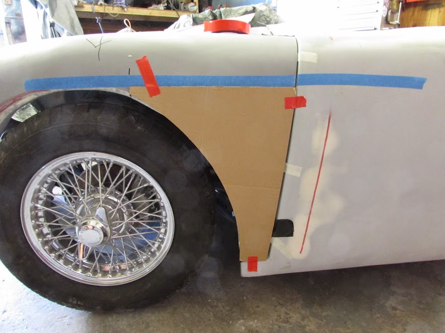
flipping the template over to the drivers side was an interesting but ultimately predictable exercise:


I have decided to use 2mm Ali as I want the strength.


Added material for the arch return and the top flange the bonnet will sit on.


Cut it out using the jigsaw, The curve of the arch BTW is actually a constant curve this time instead of a 50 pence piece as I used a piece of wire taped to the marker then tape the end of the wire to the floor so I could play with differing radius curves until I got what I wanted.


I have never done any Ali bodywork before and only had a the vice a standard hammer and a pair of pliers so for those Aluminium aficionados I apologies in advance if my ham fisted methods affect your sensibilities but sometimes you just have to work with what you have.

Started to form the lip of the arch with a pair of pliers just working along slowly using the marker line as my guide.


Pretty soon I had the return on the arch formed, the process had introduced a bit of a curve but by using the vice as a dolly and gentle work with the hammer along the flange (oo err) I managed to stretch it so that the panel returned to as close as flat as made no odds.


Next I formed the top flange using the vice a block of wood and the trusty hammer.


Cut the relevant section off the bonnet and first trial fit


The gap at the rear on this pic will disappear but the bonnet was sagging a bit when I took the pic:


A bit of gentle knee work had the right curve in the panel


A little fine tuning and a going over with some 240 revealed the hammer marks left but im hoping with a bit more gentle persuasion I can get rid of most of them and those that remain will require only a light skim of filler, they look worse in this pictures because the sanding has highlighted them.


at that stage it was nearly 19:30 so locked up and walked away feeling that at least I had accomplished something. Hopefully back up on Thursday so will try and replicate the panel on the drivers side.

TTFN
Mac
8 Jul 2014, 8:48pm
Gary the problem is that the bonnet moulds are still the original Sammio ones so until they are reworked, which im sure is on the cards it is what it is and I have to make to a remodel what I have,
8 Jul 2014, 9:01pm
Viatron wrote:
... At this point I curled up in a corner and sucked my thumb and cried for my mummy ...

Mac - Whilst your laser work has scared me, that last comment really did made me laugh. :D

Glad to see your time in the workshop ended on a positive note. :cool:

Good luck, Paul. :)
8 Jul 2014, 9:25pm
And for those of you not paying attention I have just taken my socks off and recounted and realised the difference in measurements between the 2 halves of the bonnet was in fact 80mm not 120 as I had somehow come up with bit I will revisit this on Thursday when I'm back up the unit.
Ttfn

Mac
9 Jul 2014, 8:21am
Nice use of modern technology - not the laser, that's so 1960's spoof spy movie - but the 'CAD' or Cardboard Aided Design system.

I'm sure you'll get your bonnet sorted soon.

Given the two issues you've highlighted, the difference in gap between the snout and headlights from side to side and the offside wheel protruding from under the arch, I'd be looking at cutting a line from the rear of the bonnet to between the snout and offside headlight and putting a slim, triangular fillet into the gap to widen the front on that side but keep the rear matching the bulkhead. Hope that makes sense...

Oh, and I love the alloy bonnet corners. I'd be tempted to not prep them for paint that well and scuff off the surface at the edges to show the alloy below. That would give it the vintage, hand crafted aluminium (expensive!) body shell look.

Keep up the good work. :)
9 Jul 2014, 8:24am
Hello,

I wish i had known all of this a year and a half ago!

The Spyder bonnet has some of the same problems,for example my left wheel is further in then my right.....

I,ve had sleepless nights over that and nearly broke up my whole floor-and bulkhead section because I was confinced I had build things "out of the center".

At last I was confinced by my sons:"You don't look at two sides of the car at the same time!""

Now I can live with it.

Success,Rob
9 Jul 2014, 8:35am
Towed
That's pretty much my plan but if I do it with the parts I'm replacing in Ali still part of th bonnet I will still end up with the back half of the tyre too exposed. I'm hoping that by going the route I have started down I can get the whole wheel covered...... Well that's the plan anyway
Mac
9 Jul 2014, 8:38am
Rob
I agree with the you can't see both sides at the same time theory but at the same time I would like to get it symettrical when measured only in feet and at the moment it wouldn't pass that test! The biggest issue is the covering of the DS wheel for the MOT all the other niggles can be lived with or worked on later, thanks for your interest btw
Mac
9 Jul 2014, 8:39am
Don't get too bogged down about symmetry. Apart from the scoops to clear the engines, none of these had major bonnet surgery -


9 Jul 2014, 8:41am
Towed I totally understand where your coming from unfortunately unless I'm wrong none of those are Navigator / Cordites so were dealing with an unknown quantity!
Mac
9 Jul 2014, 8:47am
Viatron wrote:
Towed I totally understand where your coming from unfortunately unless I'm wrong none of those are Navigator / Cordites so were dealing with an unknown quantity!
Mac


That's right V, they're all original Sammio Spyder bonnets. The dimensions are all over the place though if you actually measure them. The trick is not to measure them...