This is a read-only archive of the old Madabout Kitcars forum. New posts and replies are no longer possible, but every thread is still here to browse and read.
Re-reading this I remembered that Hondas of the 80s and 90s used to have very low bonnet lines - and so shorter strut (or wishbone/strut) front suspensions. Nowadays cars have higher bonnet lines to add a couple of inches of crumple for the poor pedestrians who get hit.
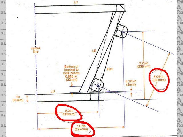
I'm no suspension expert but you do get the geometry by drawing a line from the top of the strut and intersecting it with the line created by the bottom wishbone. So I guess just shortening the strut would have an effect on geometry.
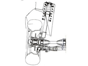
I've seen this diagram before. I would guess if the strut is shortened along the same radius it would still be ok? Looking at the photos I've attached LB's struts look almost vertical.
You're showing a drawing here of the front suspension. I'm going to copy the front suspension from my deon and it will be the same just new hub carriers.
It's the rear suspension I'm looking at altering. I know that just loping of 2" off will alter the swing radius as you say,this is must be why the LB struts are more upright.To Keep the virtual radius with a shorter strut the same moving the top mounting point out then will surely bring it back in line?
I'm hoping to get my adaptor plate cnc'd either this/next week and will start by building the engine cradle/suspension. I want to keep as close to the deon as possible.
Hi, by the way - please take my comments about engineering and suspension with a pinch of salt! I don't pretend to know much about either. If you want knowledgable feedback and people aren't answering on here then maybe posting some questions on the middy section of the locust site would get you useful responses. I'm following the discussion with interest.
cheers
Ross
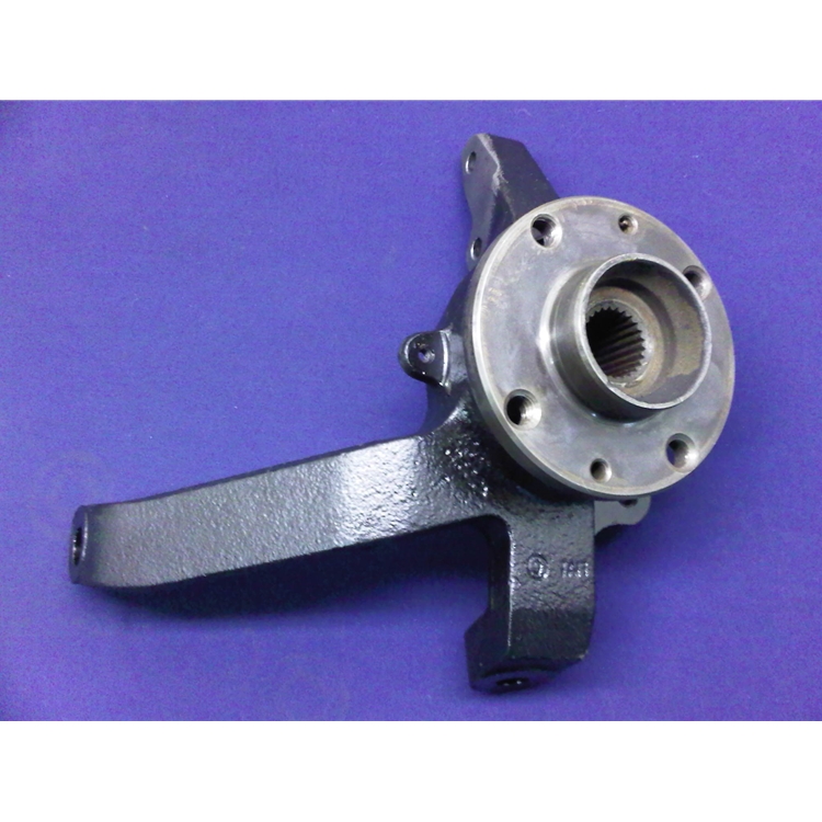
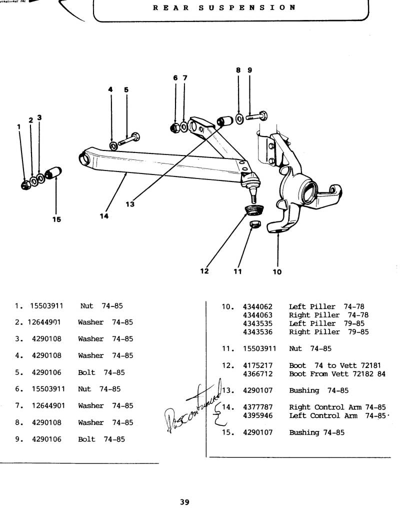
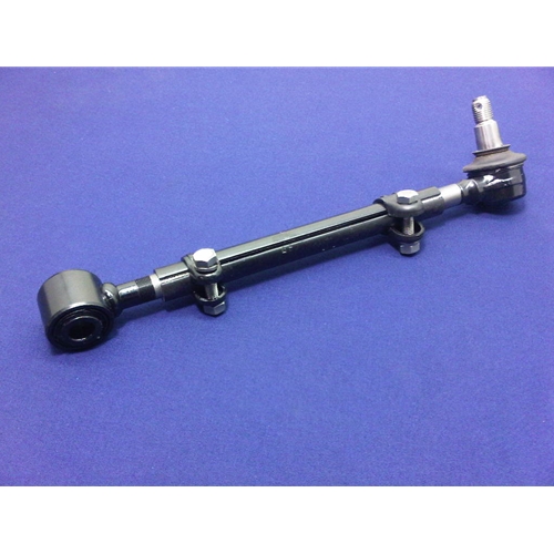
Much the same design as the Montecarlo is the Fiat X1/9. It uses the same uprights, a very wide lower wishbone and a type of adjustable tie rod to give lateral location. In the X1/9 the top of the strut is 790mm high.
The X19 uprights you show look very similar to the ones I had on a fiat 128 coupe years ago. The 128 coupe was front wheel drive so these arms were bolted to the steering rack. As they were transferred to the back in the mid-engine X19 a fixed stay must have been incorporated to stop rear wheel steer.
The deon uses a lancia beta front upright at the rear with a fixed location built into the rear top wishbone. Metal brackets then bolt to the strut mounting holes to attach the top suspension.
The deon front ones were taken from a fiat 124,and later a lada riva. And unbelievably still available new from lada complete with hub/bearings and brake discs!!
ian
Hi,
yes the Deon (and before that the DGT) were, if magazine articles are correct, fine tuned by a company called Geoscan.
It would be incredibly helpful if someone could do a drawing or simply list all the mesurements of the complete Deon suspension system. From all accounts it is very good.
Of course tyre profiles and engine weights have moved on from the 80s but it is a good starting point.
here are a couple from the Locost site as an example of what I mean:
This is a diagram of the deon front suspension. Unlike the locost wishbone where the ball joint screws in or out, the deon ones have the adjustment on both the inner arms where the wishbones bolts to the chassis rather than at the upright. The ball joints were bolted in securely. I guess this allows fine tuning of the upright angle? Both top and bottom wishbones have this arrangement.
The rear wishbones on earlier JHC cars also had this adjustment on both upper and lower wishbones ,but later deon cars had a fixed upper wishbone.
When I come to make my chassis I can draw a diagram and add sizes if anyone is interested.
You're right about the deon/jhc chassis being fine tuned by geoscan.It was said to have been tested at castle combe circuit.
Hi,
yes the Deon (and before that the DGT) were, if magazine articles are correct, fine tuned by a company called Geoscan.
It would be incredibly helpful if someone could do a drawing or simply list all the mesurements of the complete Deon suspension system. From all accounts it is very good.
Of course tyre profiles and engine weights have moved on from the 80s but it is a good starting point.
here are a couple from the Locost site as an example of what I mean:
What site are you on for this-might be worth a read-ian
These images were just grabbed randomly via google image search to show how other people had sketched dimensions. However the Locost community in general have lots of discussion about suspension design as they tend to customise their DIY, built from scratch designs using a variety of donor parts.
An interesting start to a design. Do you have a link to it on FB? At present it just looks like a version of the 1960s Dino design - which was essentially a platform design without much triangulation. It relied on some heavy big tubes and a few basic upright frames. The sports racing Dino 206sp chassis - multi tubular, small tube, augmented by riveted aluminium sheet is a far more advanced design than the road-going Dino 246. This is a replica one I saw being built in Invercargill NZ in the '90s.Its a bit like comparing a Dutton to an Ultima.
The chassis design he posted was a project for a ferrari f40 he was constructing. The fb page is just titled 'kit cars' and the post show various stages from chassis design and sizes up to a complete car. There are some nice photo's. Check out 'nitescu lon laurentiu'
Have you seen Bloozebury's Canadian project? He is modifying a Fiero, widening, lowering, changing suspension geometry, fitting a transverse V8. There are many drawings, including a rear suspension that was originally strut and has been considerably altered. His website is: http://bloozeown.weebly.com/
and there's even more detail on the Dutch Fiero site : http://www.fiero.nl/forum/Forum3/HTML/000116.html
Right-does anyone have an accurate set of dimensions for a Dino 246? I have a couple of sets of measurements from searching through my huge collections of dino books, and then several from the internet, that although similar are not the same!!! I'm after wheelbase, front track and rear track please. Or if anyone can point me in the right direction!! cheers
update--
just for reference I have - taken from the anthony curtis Ferrari Dino book which seems to be a definitive book on the dino written around 1990-
wheelbase 2343 mm (7 foot 8.25 inches)
front track 1416 mm (4 foot 7.75 inches)
rear track 1441 mm (4 foot 8.75 inches)
these tally (within 2/3 mm I guess from rounding up/down) with several other books on the dino. But I do have another book with a set giving a wider track? Could this be from the "chairs and flairs" car? or was it just wider tyres and flared wheel arches. The internet search gives varied dimensions so I've taken them as not to be an accurate account due to armchair writers giving their take on the car!!
Hi Ian
I have a Brooklands "road test" book for the Dino which is basically a compilation of magazine road tests for the car.
There do seem to be several different figures quoted in the different articles but the consensus seems to agree with those quoted in the "Motor" road test No 30/71 which gives
Wheelbase 7' 8¼"
Front track 4' 7¾"
Rear track 4' 8¾"
I'm inclined to believe the above figures as the magazine article has gone to the trouble of detailing a lot of the car's facts and figures including such esoteric facts as the King pin inclination angle (9° 3’ in case you are interested lol)
Hi, the official factory 246GT manual lists:
1425mm the front track (carreggiata a terra)
1430mm the rear track (carreggiata a terra)
my Italian is pretty basic but I think this is the measurement from vehicle centre to centre of wheel AT GROUND LEVEL.
The Ferrari brochure lists it as:
wheel base 92.2" in English (2340mm in French)
front track 56.1" (1425mm)
rear track 56.5" (1430mm)
The 206 GT is listed at rear=1400mm by the way. And the 'chairs 'n flares' would only have a different track if it had different offset - otherwise the centre of the wheel would be in the same place.
cheers
Ross in NZ
Ferrari would probably have measured in mm so the Imperial measurements are just approximate translations. I reckon the Factory manual and brochure are the best bet:
wb 2340mm
ft 1425mm
rt 1430mm
cheers
Ross in NZ
My adaptor plate has finally arrived and been offered up to the cosworth V6.
After looking at several options for a suitable gearbox I've decided to go with a E53 gearbox from a mark 2 toyota mr2 turbo. Some of the turbo guys run upwards of 400bhp!! Now these are getting quite rare and when the do come up they are snapped up within minutes or are quite pricey still requiring a rebuild. So my next option was a complete car.
Well after searching for a few weeks a suitable donor car appeared and the deal done. Low 89,000 Kilometer jap import car (not miles) dry stored for the last 4 years. I'm not a big fan of stripping rare cars that should really be put back on the road but I will sell on what I don't need-everything else apart from the gearbox/drive and intermediate shafts/starter motor/flywheel/clutch and gear selector with all cables.
I had a bit of a look through the posts and I have built suspension from scratch.
This will give you some rules of thumb that may give you a guide or confuse you more.
My approach.
Start with the wheel offset that you want for the car that you are building.
The upright ,disk and caliper has to fit inside the chosen offset.
Once you place this on the ground you then know how long the arms need to be.
Scrub radius.
A line through the top ball joint passing through the lower ball makes contact at a point on the road.
This is part of an angle called KPI
With the wheel fitted it will land somewhere on the inside of the Tyre patch, this is the scrub radius ,zero SR is the centre of the tire this will make the car very vague at high speed, front wheel drives generally have a low SR as it cancels out torque steer but not good on RWD, I would not go any less than about 60mm inside the CL off the tire.
If you have to much ,lets say it lands not under the tire contact patch but inside that it will give heavy steering and high feed back on the wheel if you get ruts on pot holes on the road.
SR helps with self centring which is very handy if the car steps out you can just let go of the st wheel and the wheels will self centre then you just regrab the wheel and you are back in control.
The lower arm height location is all about the upright lower ball joint height of the road.
You need to have the lower arm running slightly uphill to the chassis pick up point.
This will help control the roll centre movement across the car and also in the vertical position when the car dives and turns in.
A car that has poor RC control is unpredictable, EG All the weight above the RC applies a load onto the tyre, the higher the RC the less load applied.
The lower the RC the more load because you have more weight above the RC.
If a car if cornering and it has X RC then you get on it harder and the RC changes dramatically then the attitude of the car can change sometimes for the worse.
The upper arm needs to run down hill from the upright to the chassis, changing the angle will change the RC height I have found on rear eng cars it likes to be lower say at about 60-30mm of the ground.
Reason being you have less weight over the front (no eng) so you use RC to get tire loading.
Steering arm.
I like a bolt on steering arm as it gives you a better chance of getting the bump steer correct.
Steering rack location.
If it’s a front steer you need to be careful that you can get a reasonable ackerman.
On rear eng cars I always run anti ackerman meaning it has neg toe out on turn because no weight in the front the front inside tire goes into slip very early so having less to out on turn will give more grip on entry but makes no difference after apexing.
Also having the rack forward of the steering arms on a front steer will give the same effect.
Upright
What ever you choose you need to know the KPI if it has 6 deg that is about the caster you will run as a starting point.
Knowing this will give you a point to start on upper arm length and setback for the upper ball joint.
Rear roll centre
Very important on a rear eng car as they generally have to much rear grip because of the weight on the back tire.
This will generally cause under steer issues because the rear just keeps overpowering the front tires.
To sort this you raise the rear RC and reduce the grip and it balances the car and allows you to get on the power early and get it to sit on the back tire at point of entry.
Hope this helps you make decisions on set up or what components to pick.
Bit hard to change RC on struts from memory ,probably easier to adjust the lower inner up or down.
One thing I have seen done and it was smart was a strut leg was cut down and a fitting welded in that had a 5/8 thread in it to accept a rose joint that was fitted in the upper arm, so the leg was turned into an upright.
That arm in your pics made to take a r/joint as a ball joint is fine but you cant do that on the loaded arm ( the one with the spring/shock attached) say the lower you cant use that idea it will break eventually, I know this because I have done it and it did break at 23.000km road and track miles.
Any r/joint if in single shear (upper lower b/joint, outer tie rod on steering arm) should have a washer larger than the joint so as it is still captive if the joint fails.



 . This is a replica one I saw being built in Invercargill NZ in the '90s.Its a bit like comparing a Dutton to an Ultima.