MadaboutKitcars

This is a read-only archive of the old Madabout Kitcars forum. New posts and replies are no longer possible, but every thread is still here to browse and read.

Berlinetta Restoration 2015

28 Jan 2015, 9:28pm
Thanks John, makes a lot of sense. In a way I would prefer to use the dual outlets for the front and the single outlet for the rear, however I am concerned about line pressures.

I just calculated it and the difference in piston area (output pressure) is 10% between a 19mm bore and a 20mm bore.

20mm bore = 314.16 Sq. mm.

19mm bore = 283.63 Sq. mm.

My guess is that BMW will have used a very small rear piston at the back, which are also probably disks. I have about 17mm piston (not actually measured it) drum brakes. So to keep the pressure differential safe I feel I should be keeping the bias towards higher pressure at the front, else I may have trouble with back brakes locking up in the wet even under light braking. I once had a Mini with a seized pressure limiter at the back, that was a regular for swapping ends unexpectedly! :icon_lol:

While with a Mini that's kinda acceptable, with a Marlin I think I may loose friends and passengers pretty quick. LOL
28 Jan 2015, 10:22pm
8 Valve Ed wrote:
I have a little puzzle, my brake master cylinder is from a BMW, I don't know which, although I think I was told once...

I have started to pipe up the brakes and the old chestnut of which port goes where arrises once again. It would have been very convenient if the front brakes were connected to the back part of the master cylinder because that has two ports, and the back circuit to the single port at the front of the master cylinder.

However, given the rear outlets are marked 20 (mm?) and the front outlet is marked 19 (mm?) I am assuming the front outlet should go to the front brakes via a 'T' piece and the rear outlet with one outlet port blanked off, to the back brakes. That assumption because usually you need a greater pressure to the front brakes, the back brakes just assisting, also you don't want the back brakes locking up well before the fronts have started to bite.

I have made a photo of the m/c; beside the 19 and 20 markings there is a letter, my query relates to the letter, does it indicate H and V to indicate F and R (front and rear)?

Also, can anybody explain why there are two outlet ports on the outlet marked 20?

Any suggestions will be appreciated, while I could look a word up, H and V are difficult to look up! ...Just thought, perhaps I just look up Front and Back in German?

Anyway, any suggestions still appreciated.


Ordered the gaskets for the engine today, may start assembling that tomorrow. :icon_biggrin:


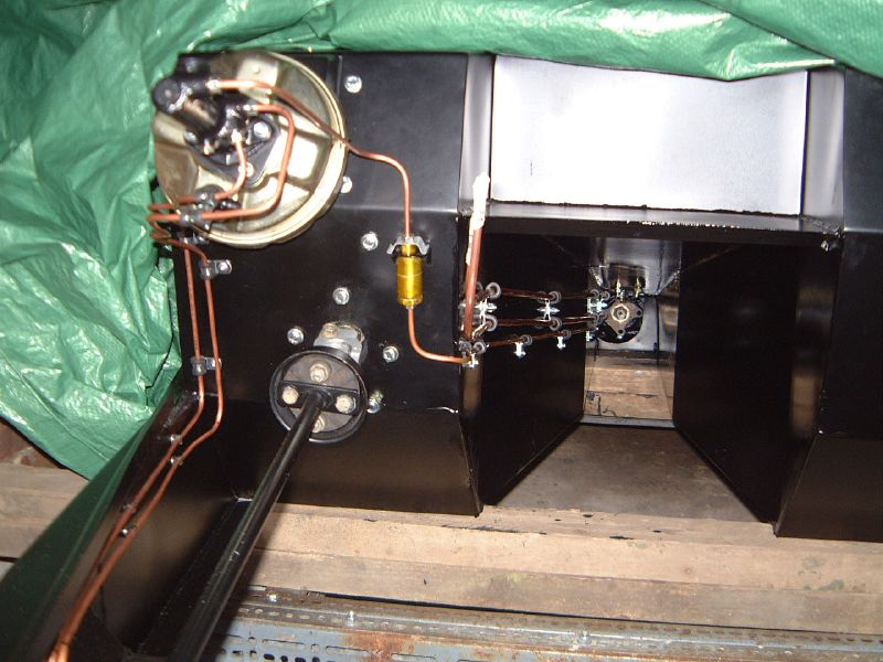
That looks like the BMW master cylinder that came off my BMW 320i donor car. The two ports nearest the pedal pushrod are for the front disc brakes. The single port is for the rear brakes which were drums on the 320i. The rear brakes also have a pressure reducing valve (BMW part number 34331152494) between the M/C and the tee piece in the rear brake line.

You can see it here fitted in my Marlin Sportster.....

Brake line sand fuel lines by marlinpeter, on Flickr

Sorry that this old photo is a bit blurry. You should be able to get the pressure reducing valve from any scrap e30 BMW if you need one.

I hope that helps?

...peter
P.S. i don't know what the letters stand for :noidea:
28 Jan 2015, 10:33pm
That's the one Peter! together with the servo, off camera...

It never found it's way onto the Roadster, I had intended to fit it after it went on the road but that never happened of course. :pout:

Thank you for clearing it up, especially the photograph, a picture tells a thousand words! I will go search for a pressure limiting valve, shouldn't be too hard to find.

I am still struggling to find the rubber seals for the header tank, my local BMW place quoted £100 + for a kit... LOL Perhaps if I find a regulating valve I will also find another master cyl and header tank, with seals.
28 Jan 2015, 11:14pm
8 Valve Ed wrote:
That's the one Peter! together with the servo, off camera...

It never found it's way onto the Roadster, I had intended to fit it after it went on the road but that never happened of course. :pout:

Thank you for clearing it up, especially the photograph, a picture tells a thousand words! I will go search for a pressure limiting valve, shouldn't be too hard to find.

I am still struggling to find the rubber seals for the header tank, my local BMW place quoted £100 + for a kit... LOL Perhaps if I find a regulating valve I will also find another master cyl and header tank, with seals.


You probably know that servo is off a BL Metro which were a bit limited in the amount of boost. (lots have upgraded to Dual Diaphram boosters from the USA, but that's another story...)

The seals should be available separately and should be about £5 each. (Part number 34311160133)

Just been looking again at realoem.com and BMW fitted 19,05/20,64MM M/C up to 07/1986 (like yours) and after that fitted 22,20/17,46MM. I don't have my Sportster anymore so I can't tell you exactly which one was fitted. The pressure reducing valve goes with the later 22,20/17,46MM master cylinder so you may not need one on yours?
Maybe other BMW Sportster builders will be along to comment as my memory is a little hazy from about 10 years ago :lol:
30 Jan 2015, 10:51pm
Peter, sorry for the delay replying, been a bit distracted.

Yes I am aware of the dual servo but I feel the car being so light, circa 700Kg and my being well used to non servo brakes, even prefer them, it shouldn't be an issue.

Thanks for the part number of the seals, I will follow that up, if my local dealer can't (or won't) supply is there an on-line source of BMW parts?

For now I am going to try the conventional layout of the rear piston for the front brakes and the front piston for the rear brakes. I think the rear piston area will be reduced by the shaft which links the front and rear pistons, so that will reduce the effective piston area. I may even do some pressure tests just to see what happens.


Now for the bad news, I have found that my 'best' engine block isn't so good after all. I have been de-greaseing and cleaning it carefully. Now it's cleaner, I have discovered the bores are badly scored in their lower half's and worse, #8 cylinder sleeve has dropped by 12 thou. My engine man isn't too concerned about the scoring but suggesting topping the block on both sides to get the deck down to the top of the liner. We discussed trying to pull the liner back up the block but I am apprehensive about that it seems it can take 20 tons force to move them, and that's down, with a good face to push on. To pull one up would need a special dolly and there is very little room to play inside the crankcase.

I do have another SD1 block, so tomorrow I intend to clean it carefully and see which is the better block.

Otherwise making good progress, crept over the 60% complete this week, I think Easter is a realistic target. :flypig:
30 Jan 2015, 11:48pm
Another project...

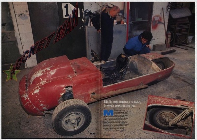
A friend has just eMailed me to say he has collected a new project today, a Mini based trike which built by Reg Curley in 1968 and turned up in an article in Mini World for March, 1994. Reg has passed away but the trike was handed down to his son. However he hasn't made any progress with it since then so my friend followed it up and has eventually taken it on. It's ripe for restoration and I hope to be involved in some way.

It was used for racing but wasn't very successful, largely due to the engine etc. not being very well developed.

31 Jan 2015, 10:56pm
8 Valve Ed wrote:


Thanks for the part number of the seals, I will follow that up, if my local dealer can't (or won't) supply is there an on-line source of BMW parts?


I've always found BMW parts departments very helpful guys. (my local one will even deal with request by email). They once ordered in a 29p part for me from Germany without any extra charge.
However, there is a BMW shop on ebay....http://stores.ebay.co.uk/BMW-Direct-Store You could try them if its more convenient. This part is not currently listed but they do say to contact them for any part not listed.

BTW that mini based trike looks very scary to me!!
2 Feb 2015, 6:49am
That mini trike looks exciting, I assume it's not road legal?
3 Feb 2015, 7:12pm
Hi, the Mini based trike is really nice, I saw it on Sunday and had a really good look. I am still digging trying to find it's origins. It's purely a track trike, it would originally have been use alongside sidecar outfits. Once it's back in running condition it will be racing in the British Historic Championship alongside three wheeled Morgans, other three wheel specials and historic sidecar outfits.

Here it is with my two boys at the helm! It was hard prising them out of there after the photo shoot I can tell you...


This is what they get up to... The Morgan is running on Methanol, the Berkly is a Mini based special. One of my better snaps!


I have been hard at it doing numerous jobs on the Marlin but it's been extremely cold for the last few days, the cold seems to draw all my energy, when I have finished about 9pm I am deadbeat, a little supper and bed.

Today I have cleaned the small parts of the engine ready for the build this weekend. I have cleaned both SD1 blocks and finally decided to run with the one with a dropped liner, it's only 12 thou and the head gasket does not grip on the liner so I will take a chance. The other block has several bad dings in one deck right where the sealing ribs of the head gasket are, so it either needs decking severely or find somebody to put some dabs of TIG weld in the dents. I have taken the bulkhead and pedal box out to paint them, I will probably fit the engine and gearbox first before I re-fit the bulkhead and pedal box.
5 Feb 2015, 9:14pm
A big relief.

Today I tested the radiator, one of 'those' tasks I have been putting off. I had gradually gathered all the gear I needed and decided since it was such a nice morning I would tackle it.

I suspected it would leak because the water pump had been trying to drill it's way through. When I collected the car the water pump shaft was almost touching the core where the damage is so I was expecting the worst.

Apart from the fact the water pump was far too close, I later realised the main cause was that the back axle moves forwards and backwards as the axle rises and falls, in that order. That isn't unreasonable but, it moves over 50mm, The Rover SD1 propshaft which was fitted only telescoped 25 to 30mm meaning that on full bump the engine was pushed forwards up to 25mm, into the radiator. I know the suspension has been at full bump frequently because the propshaft has been gouging bit's out of a crossmember.

I have moved the engine back by 125mm (5 inches) so that won't happen again!

Anyway, I have a few pix of the operation on the rad. Four of the core tubes were damaged by the water pump and had been rather badly soldered. The Rad is actually in quite good condition, it has been specially made by Serk, with their label on it and it's own serial number. I ground out the bad soldering with my Dremmel type tool, I tried to melt it with my Weller gun but it wasn't hot enough and I felt the blow lamp might do more damage than good.

I had already soldered two of the tubes before I took this pic.


This was my setup with a pressure test using air inside the rad and soapy water to test for leaks. It's easier than filling the rad with water, especially when you are expecting to have to solder.


This was the result after I had finished soldering, there were no more leaks from the damaged area, even though I took it over 15 psi.


This is what it would have looked like if it had been leaking! This was only a tiny leak but it created a lot of pretty bubbles.


After lunch I switched to painting mode... I prepped the bulkhead and gave it it's first coat of paint.


All in all a great day, very satisfying. The rad will have to be watched but I'm pretty confident it will be OK. Once the dust settles I may have a new core fitted but probably not this year.

Tomorrow I have a little welding to do under the scuttle. The brackets which hold the scuttle on need trimming and final mounting a bit better than they are. I am planning to build the short motor this weekend. I have the block to hone and polish up the big ends but otherwise I think everything is ready.

:icon_biggrin:
5 Feb 2015, 9:23pm
I like your bubble sculpture :D Looking good :)
5 Feb 2015, 9:26pm
Thanks Patrick, I have to admit I was rather taken with it myself. Bit like a Christmas tree, I liked it better because it wasn't a leak!
5 Feb 2015, 9:35pm
I forgot this should have been posted on the first Feb.

My updated progress chart to the end of January. Just crept over 60% overall.

5 Feb 2015, 11:35pm
8 Valve Ed wrote:
Hi, the Mini based trike is really nice, I saw it on Sunday and had a really good look. I am still digging trying to find it's origins. It's purely a track trike, it would originally have been use alongside sidecar outfits. Once it's back in running condition it will be racing in the British Historic Championship alongside three wheeled Morgans, other three wheel specials and historic sidecar outfits.

This is what they get up to... The Morgan is running on Methanol, the Berkly is a Mini based special. One of my better snaps!


With Bill Tuer at the controls and Maggie his passenger there is nothing that touches this Morgan - he is completely without fear - and Maggie must be too to be his passenger! He'll pass on either side, and go off the track and do it on the grass if he has to. He is just brilliant to watch, and you can not see Maggie as the passenger as she gets down so low! Just fabulous to watch at our local Cadwell VSCC meets.
6 Feb 2015, 7:26am
Yes, I miss my visits to the classic circuits, Bill is without doubt spectacular, as you say Maggie is rarely seen above the dash. An interesting 'feature' of Bills Morgan is that on the overrun it spews Methanol out of the carb inlets and sprays any following riders generously. The visors aren't just to keep the wind out.

Oh, and the smell of Castrol 'R'. :icon_mrgreen: :icon_mrgreen: :icon_mrgreen: :icon_mrgreen:

Once we get the Curley Trike back in competitive condition we will be back. :icon_wink:
7 Feb 2015, 11:09pm
The Engine

Today was spent on the engine, cleaning and preparing. We fitted the crank and fitted #1 and 2 pistons, TWICE!!! Hope you guys find this funny... I fitted them in # 7 and 8 bores... Realising my mistake, with a rather red :embarassed: face, we pulled them and re-fitted them in the correct bores. :noidea:

At least I realised before all 8 were in place. :icon_biggrin: At least it was an easy mistake to rectify. :dizzy:

After that we retired to the house. Enough excitement for the day, I will take some pix tomorrow. We decided one problem was we don't have a bench to put things on ready to assemble, tomorrow we plan to make a little table to put things like the pistons and tools so we can see them and don't spend more time looking for them than using them.

Michael, my son remarked that it will be great when we can actually ride in the car and enjoy days like today exploring the lanes and enjoying using the car on the beautiful days we get here. The sunset was amazing this evening, the sky was bright red for ages and it reflected off many of the surrounding houses windows.

I am glad I held off assembling the engine until Michael could be involved, he is only 14 and this is the first engine he has helped assemble. He has torqued up all the bolts and has a better understanding of what goes on in the innards of an engine. I hope to finish the assembly of the short motor tomorrow, fitting the remaining 6 piston assemblies (in the correct bores... :dizzy:) and fit the the cam and timing gear.
8 Feb 2015, 11:24pm
The Engine Build

Today we assembled the rest of the short engine, the only problems we encountered were the flywheel bolts were useless and the front cover bolts were playing hard to find. From three engine sets I was pushed to find a full set of usable bolts to attach the front cover.

The flywheel bolts were only 'S' quality instead of 'T' quality, they were supposed to be 1" long bolts, in fact they were setscrews, (threaded to the head, instead of having a plain shank under the head) they varied from ¾" to 1 1/8" long which had bottomed out in the crank, also the ends of the setscrews were cut off at hellish angles. Rimmers have the correct bolts, but I will try to get some locally in the morning.

Here are some photographs of todays excitement, Michael was a great help, ending up taking over the assembly and leaving me to prepare each part ready for fitting.

Fitting the ring compressor to the piston.


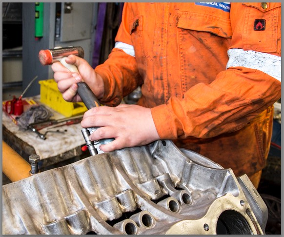
Tapping the piston into the bore.


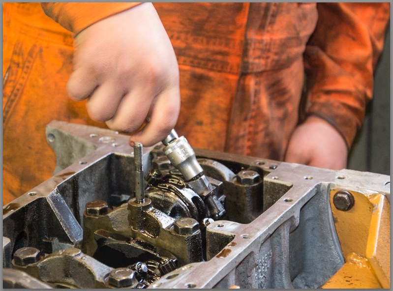
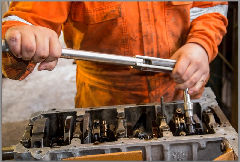
Screwing the nuts onto the big end cap bolts.


Torquing the big end nuts up.


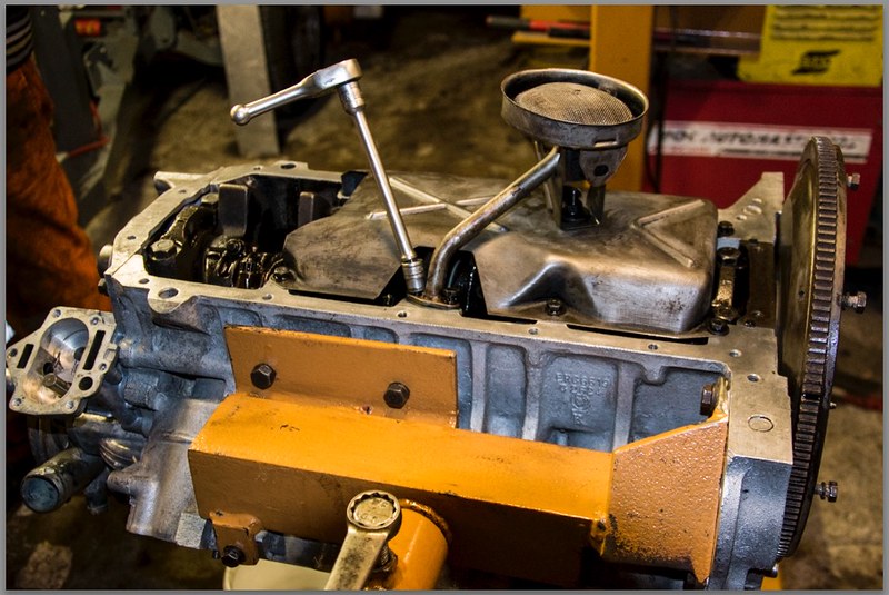
Finishing touches ready for the sump to go on.


Enough excitement for one day!

# [COLOR="white"]1050[/COLOR]
9 Feb 2015, 7:15pm
In an earlier post Paul L kindly provided a link to a very interesting technique for creating hinged panels, doors, bonnet and boot lid etc.

http://www.ffcars.com/forums/2642315-post17.html

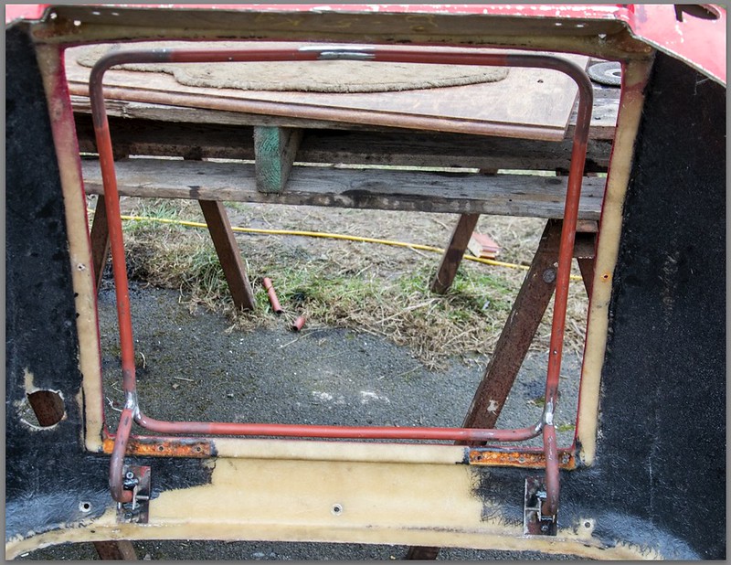
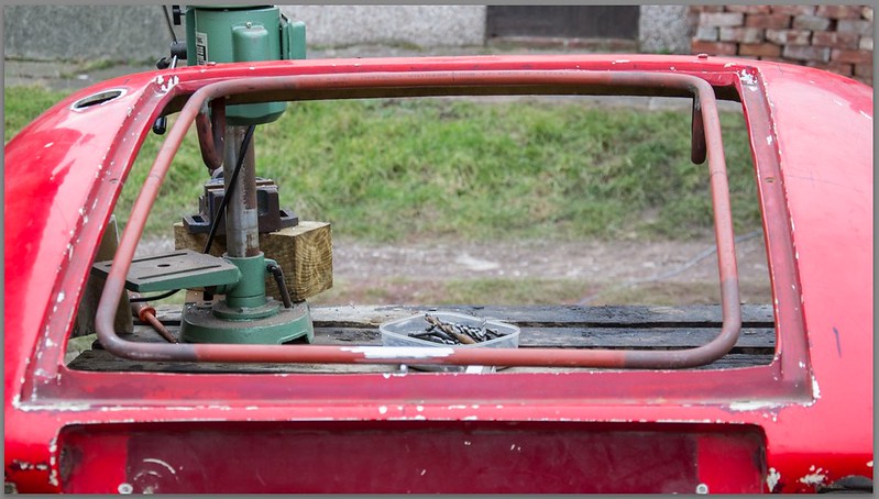
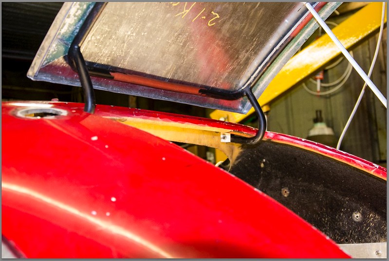
Basically it uses a tubular frame, attached to the hinges and the catch/lock, the frame has a sheet aluminium flange which is dressed to the tube and riveted on. The flange is then adjusted to fit the aperture, then clad with a single outer skin. This method allows the frame to be adjusted exactly to fit the aperture both for size and alignment before the skin is attached to the frame. It also allows for secret hinges and keeps fasteners out of sight, neat idea.

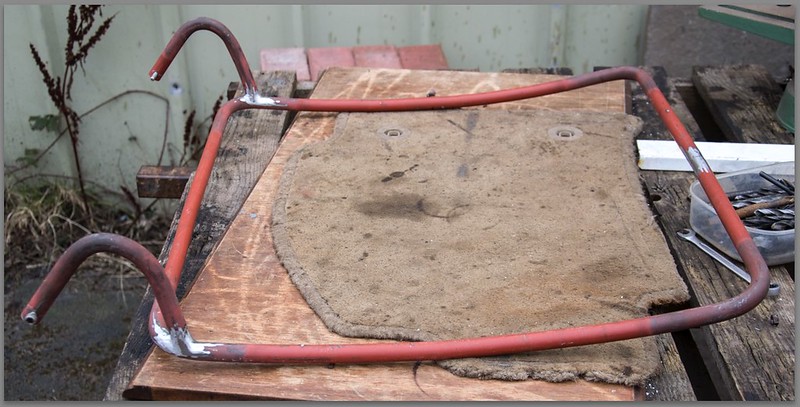
I finally obtained some suitable tube over the weekend. It's nominal bore 'black iron' (In reality, red!) tube, in order to minimise weight and cost I chose 3/8" nominal bore tube, this is about 12mm bore and 17mm o/d. My challenge was to bend it to a suitably tight radius without it kinking or collapsing. Today I overcame that obstacle when I tried my large blow lamp. It was man enough to heat the tube to red hot reasonably quickly. Once red hot it bent fairly easily and with good grace, no signs of kinking or other silliness.

Here are some pix of the frame laid on the underside of the boot lid. It isn't a perfect match for the curves but I believe close enough to get the job done. I have started creating the first hinge and I am very pleased with how it's shaping up. Hopefully tomorrow I will have something to show.


10 Feb 2015, 8:19am
Ed - Glad that link was useful, as you are clearly doing a great job. :cool:

I also love the fact that your son is getting involved and helping with the engine build.

Good luck, Paul. :)
10 Feb 2015, 8:55am
Thank you Paul, I think sharing links is one of the key aspects of a good forum, it helps everybody, and sometimes opens up new, unexpected avenues.

Michael and his younger brother Christopher spend every weekend and all their school holidays with me. They love taking stuff apart and building their own 'creations' I have made Christopher his own little bench complete with a vice where he can play to his hearts content (Provided he doesn't do too much hammering!). :smash: :nod:

On a different tack, I took a look on eBay last evening, just out of curiosity rather than looking for anything specific. I lost access to my account last year due the the security breach. All attempts to reset my password failed, I never got my reset eMail so couldn't reset my password. I don't do much on eBay now but I may want to in the future so I was a bit concerned at the loss of my account.

I didn't want to create a new account because although my feedback is pretty low in numbers I joined eBay in 2001, so it goes back a long way. Also I have a rather amusing username - irealyhatepcsalot - which often raises amusement from other eBay users I deal with.

Anyway, last evening just for fun, I tried the "reset password" button AGAIN and low and behold, it worked, they have revised the mechanism to reset passwords. So if anybody reading this has a similar problem, just try again, it worked for me this time. So I am able to buy and sell again!!! :icon_biggrin: :yo:

Better get out there and DO something... LOL
10 Feb 2015, 11:39pm
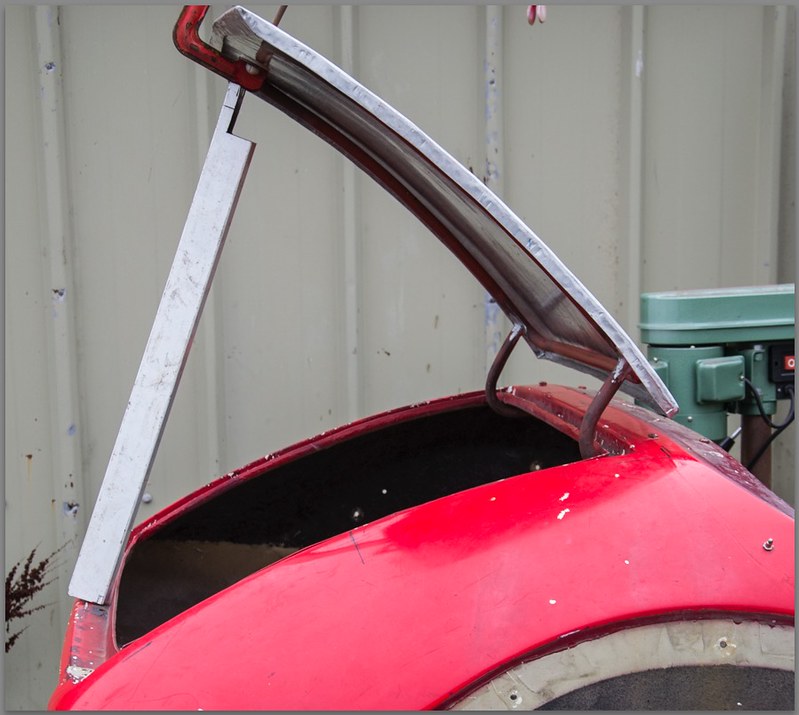
Well I had a good day! I eventually tore myself away at half past nine, having almost finished mounting the boot lid.

I am so pleased with the results of this. Some of it has been very tricky but I have got there in the end. Bending the hinges was a challenge to get them both the same.

When I checked the post after lunch I discovered a little package from Rimmers, 6 Flywheel bolts! The exact right ones, almost exactly 24 Hrs after ordering them on-line.

Two of the old bolts are on the left, The new bolt is the third from the left, the right hand bolt is from the Auto Gearbox drive plate.


Am pretty tired now, I think the pix speak for themselves. Tomorrow I hope to finish the boot lid and maybe start preparing the cylinder heads.


Zzzzzzzzz...
12 Feb 2015, 9:19am
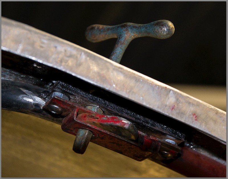
I finished fabricating the boot lid yesterday, I added the final support flanges and two old fashioned 'square key' locks. The lid is effectively done now but I still have to clean and paint the support frame before bonding it to the lid.


I tried to find an old fashioned escutcheon to cover the two keyholes either side of the lid. I came upon this site which supplies commercial vehicle body parts. They seem to have an very good range of fittings, well worth browsing the sections particularly the locks and handles, I think their prices seem to be very competitive compared with the usual kit car parts suppliers.

This is the type of escutcheon I need.

http://stedall.co.uk/product/escutcheon-cp-3-hole/

I started stripping the cylinder heads last night so I now have 16 valves ready to grind in... Will clean up the heads today, although the dry weather seems to have finished, we have very fine drizzle this morning. :-(


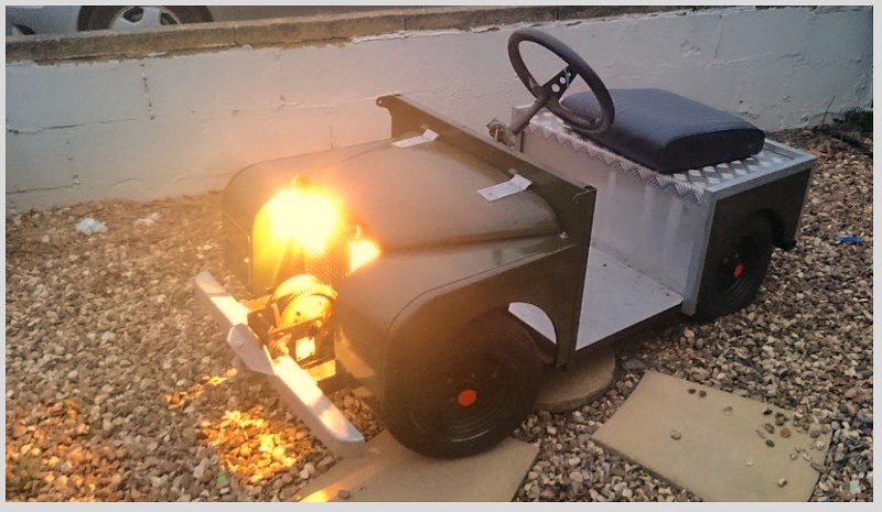
Last evening I had an eMail from Michael my son, it seems he has made the lights work on his Land Rover... He borrowed? the battery off of his mothers car and wired the lights up himself!


She was so impressed I don't think he is in trouble for 'borrowing' the battery.

Must make a start.
12 Feb 2015, 11:36pm
A Question...

Constructing my tubular boot lid frame, I needed to rivet aluminium flanges to the steel tube frame.

I found the rivets set (the stem broke) far too easily. As a result the aluminium flange was not clamped as tightly to the tube as I would have liked. It's years since I used 1/8" pop rivets but I remember them capable of squashing two panels together very firmly. These rivets are Screw-Fix specials, are there 'better' rivets out there, which are capable of pulling components together?

Can anybody make a suggestion where I can get something more powerful please.


Ooooh! I'm a Senior Member!!! :eusa_dance: :hat:
14 Feb 2015, 10:24pm
Friday 13th...

My bad luck was a stripped spark plug hole. It was extremely tight to remove as you can see from the slippage marks on the flats.


I have 4 SD1 heads, one now has a stripped spark plug hole on cyl #4. I have run a tap through it but really it needs a helicoil. I would say about 1/3 of the threads are OK, 2/3 are not. Trouble is that on close examination neither of my 'spare' heads are much better, both have sustained damage while they have been stored and in frequent moves from one location to another.

At the moment I am staying with the first head with the stripped plug hole. I have tried a plug and it seemed to take a reasonably tightness without seeming to yield.

On a more positive note I finishes assembling and fitting the distributor, which meant I could assemble the oil pump. The Rover V8 has one particular characteristic, the oil pump is set high and dry, not submerged in the sump like many engines, therefore it needs priming before it will pump oil. The standard method is to pack the oil pump with Vaseline which then causes the gears to suck up the oil from the sump on first starting. The Vaseline then dissolves in the oil once the engine is running and up to temp.


Once the engine is fitted things can leap ahead with the build. I hadn't realised what a logjam it had created.
15 Feb 2015, 9:19pm
The Boot Floor

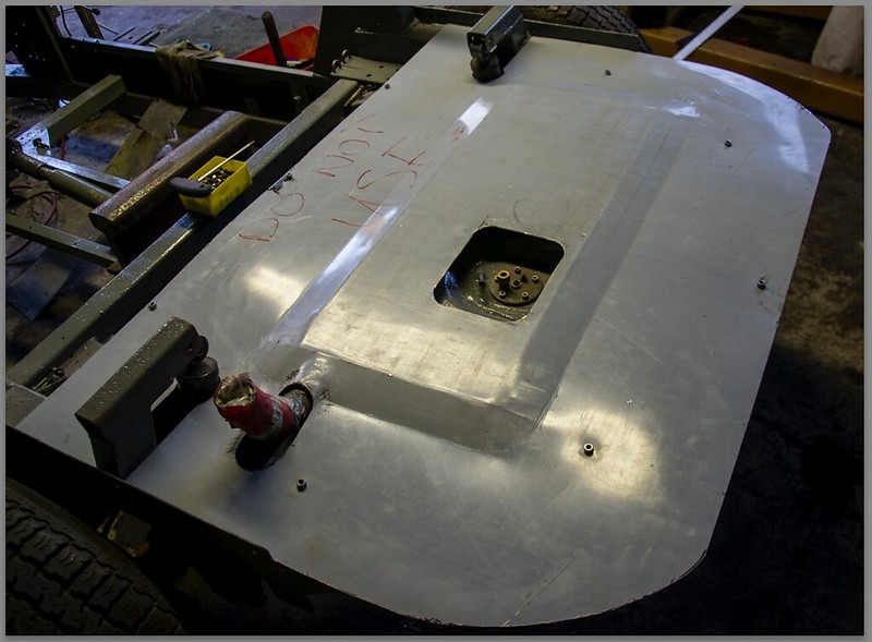
Today I set myself the target of making and installing the Boot Floor.

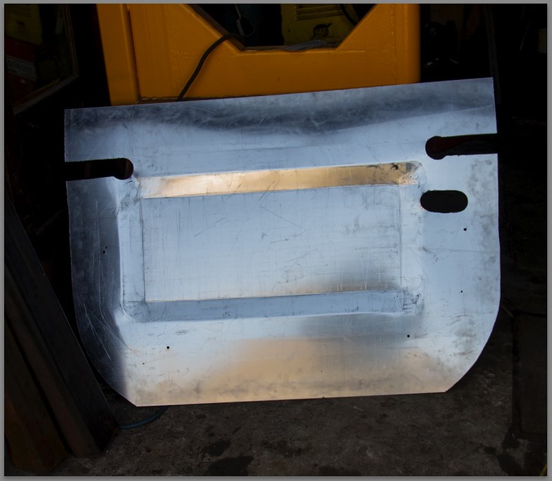
I had 'found' a nice piece of 2mm sheet aluminium to make the floor with. The original floor had been a piece of 12mm Far Eastern plywood which had seen better days.

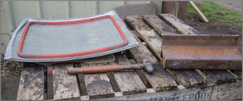
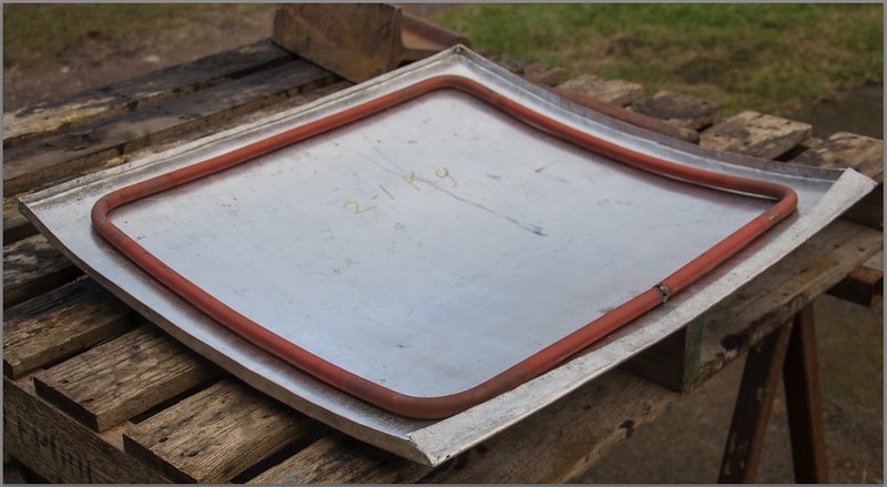
Despite me lowering it by 6mm the fuel tank still seemed to stick up about 12mm too high. I was reluctant to lower it any more. My answer was to put a 'power bulge' into the panel, that served two purposes, firstly to accommodate the fuel tank and secondly to strengthen the boot floor.

I used the English Wheel to raise a rim around the affected area, by 'tipping' the sheet while pushing the metal through the rollers with little or no pressure on the metal. I had never done this before so I was pleased when it seemed to achieve what I wanted. After I had raised the area, I stretched the area above the fuel tank by rolling it to a slight crown to help it relieve any stresses in the panel and to help push the power bulge up a little.


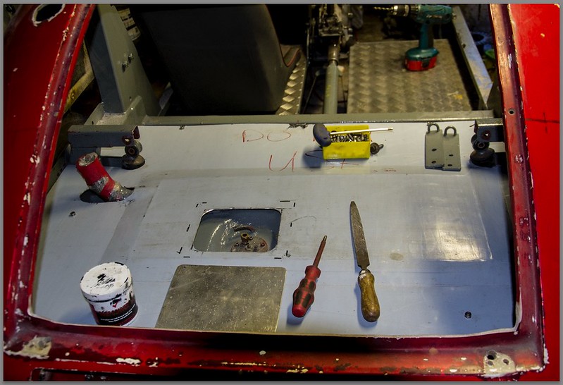
This seemed to work well enough with a little adjustment and fine tuning. So I went on to bolt the panel onto the chassis and cut an access hole for the fuel pipe connections and sender unit.

The peculiar colour is from the protective plastic film combined with the fluorescent lamps in the garage.


Made a small cover for the access hole. Will probably fix it with stainless self tappers.

Tomorrow I plan to assemble and fit one of the cylinder heads.