MadaboutKitcars

This is a read-only archive of the old Madabout Kitcars forum. New posts and replies are no longer possible, but every thread is still here to browse and read.

Swifty's Navigator

12 Apr 2014, 11:44am
How do you start? Do you have to draw it up and make note of measurements?
13 Apr 2014, 4:56pm
adventuresoftimtim wrote:
Wow impressed with the machining skills mate!!

Thanks, after many years in engineering i can now use the skills for my own pleasure.
13 Apr 2014, 5:05pm
garyh wrote:
How do you start? Do you have to draw it up and make note of measurements?


Hi Garyh Yes i start by looking at the part or parts that the new machined component will fix too then base the new part around those measurements, sometimes if its a simple job i will make and measure as i go along using my eye for judgment as i did with the hand brake ally handle.

The one time i do make a cad drawing is where the shape is less simple with PCD's etc, for example when i eventually make the adapter plate for the type 9 gearbox to attach to a GT6 bell housing i will measure accurately with no wastage as the cad drawing gives me information at the click of a mouse that would require various calculations done long hand using trig, the beauty of modern technology.
13 Apr 2014, 5:59pm
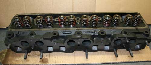
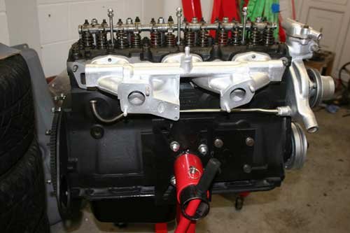
The cylinder head is now re-assembled and back on the engine so one more step closer.

IMG_4175.jpg
IMG_4183.jpg


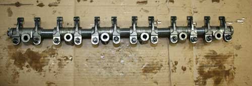
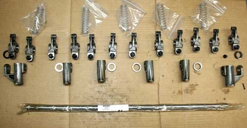
Rocker shaft parts laid out pre assembly to check the layout and then the Rocker shaft assembled ready to fit to the cylinder head, the rockers are handed left and right and there are spacer washers which have to be added to the shaft in the correct sequence, all in all a simple task.

Attachment “IMG_4189.jpg” from the original forum could not be reliably recovered.
IMG_4192.jpg


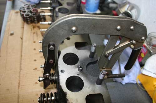
Valves in head with new springs ready to fit. The next image shows the valve spring compressing tool used to compress each valve spring so the retaining collect can be fitted.

IMG_4193.jpg


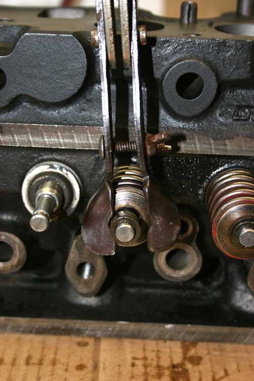
Another image of the valve compressing tool showing the point where the spring top seat and collect go onto the top of the valve stem. If you look at the valve on the right you can just make out the split taper collect that stops the valve popping off the valve stem, the compressed valve has the split Collete's fitted prior to releasing the tool.
13 Apr 2014, 6:16pm
More images of the cylinder head overhaul.

IMG_4190.jpg
Attachment “IMG_4191.jpg” from the original forum could not be reliably recovered.


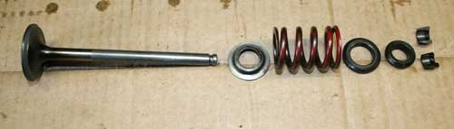
These images show the difference between the inlet and outlet valve fittings, the left hand image has two components to the Collette retainer whilst the right hand image shows only one component.

IMG_4187.jpg
Attachment “IMG_4188.jpg” from the original forum could not be reliably recovered.


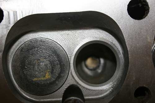
This images shows the hardened exhaust inlet valve seat, you can just make out the different colour metal ring. The next image shows the valve after the valve seat was lapped in, you need to see a gray colour band all the way around the valve taper seat.


IMG_4195.jpg


All the valves are now fitted to the cylinder head, valve stems and guide bores etc were lubed with engine oil prior to assembly, also the rocker shaft oil feed galley in the cylinder head was checked with compressed air to make sure its clear.
13 Apr 2014, 6:37pm
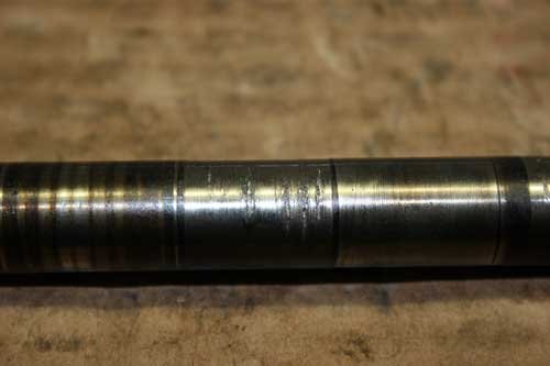
This section shows the wear on the old rocker shaft.

IMG_4179.jpg


The new rocker shaft at the top has deeper flats machined, i think this may be an improvement to help in lubing each rocker as they pivot on the shaft at this point. I have laid the old shaft next to the new so you can compare between old and new.

IMG_4178.jpg


You can see the extreme wear on the rocker shaft where one of the rockers rotated, it looks like the shaft has been starved of oil at some point, just about all the rockers had picked up the same as this one, poor maintenance by a previous owner, so let this be a warning to regular checking and changing the engine oil.

Attachment “IMG_4176.jpg” from the original forum could not be reliably recovered.
IMG_4184.jpg


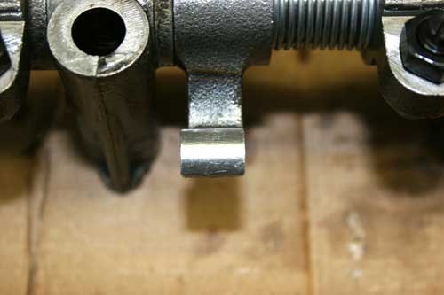
This shows the point where the rocker comes into contact with the valve stem (the point you put the feeler gauge in to adjust the gap, this images shows the rocker arm upside down), the valve stem has worn an indentation into the rocker toe. The second image shows what a new rocker looks like, no wear at all. Apparently this wear affects the angle at which the valve opens so effecting the performance of the engine.

IMG_4203.jpg


The cylinder head fitted and torqued down, valve timing is checked to make sure its correct i did set the cam shaft up with a dial gauge on no 1 piston prior to fitting the cylinder head, then each valve gap is set to the correct tolerance. Made three new rocker box studs out of my favorite material, stainless steel.

Job done and the engine is beginning to come together, the real test will be when i start her up so fingers crossed all will be ok.
13 Apr 2014, 6:43pm
That's looking really good. Keep going!
13 Apr 2014, 6:58pm
Swifty, its so helpful to have the detailed descriptions. I will use these as ref. in my build.
13 Apr 2014, 7:12pm
garyh wrote:
Swifty, its so helpful to have the detailed descriptions. I will use these as ref. in my build.


Not a problem Garyh, if you ever need any advice drop me a line and if i can help i will.
14 Apr 2014, 6:37pm
Swifty - Your engine looks good from the outside & the inside!

Good luck, Paul. :)
15 Apr 2014, 7:12pm
Not a great deal done today, started to manufacture a bespoke coil cover, hopefully i will have it finished tomorrow, will then post some pictures.


IMG_4200.jpg
IMG_4197.jpg


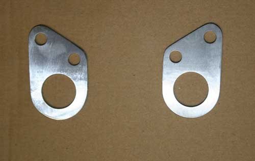
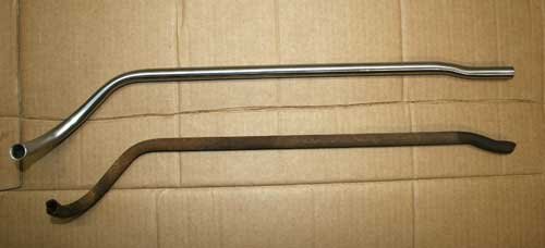
Made a couple of engine lifting brackets out of 3mm stainless and a stainless water pipe as the original steel pipe was rotten.

Cleared the garage out ready to wheel the chassis in to start stripping it down before i send it off to mates to be shot blasted and etch primed, was thinking of having the chassis galvanized but may just coat with a quality chassis paint and wax oil the internal parts.

Well that's it for now not much to talk about today see you soon.
18 Apr 2014, 7:35am
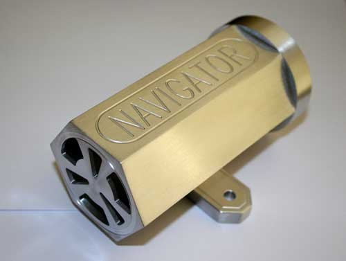
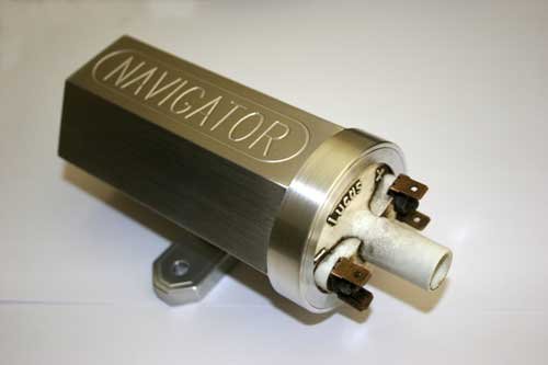
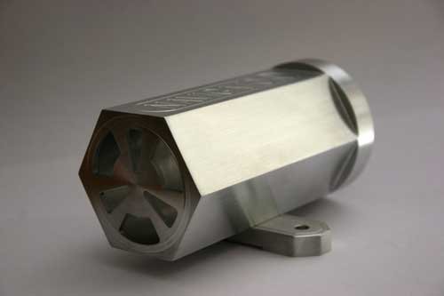
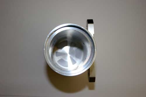
Finally finished the ally coil cover so posted a few images, bored out from 80mm bar to suit the coil, made a ring cover to finish the open end when coil fitted. Hex machined with dividing head along with the end vent pattern.

IMG_4222.jpg
IMG_4223.jpg


IMG_4226.jpg
IMG_4221.jpg


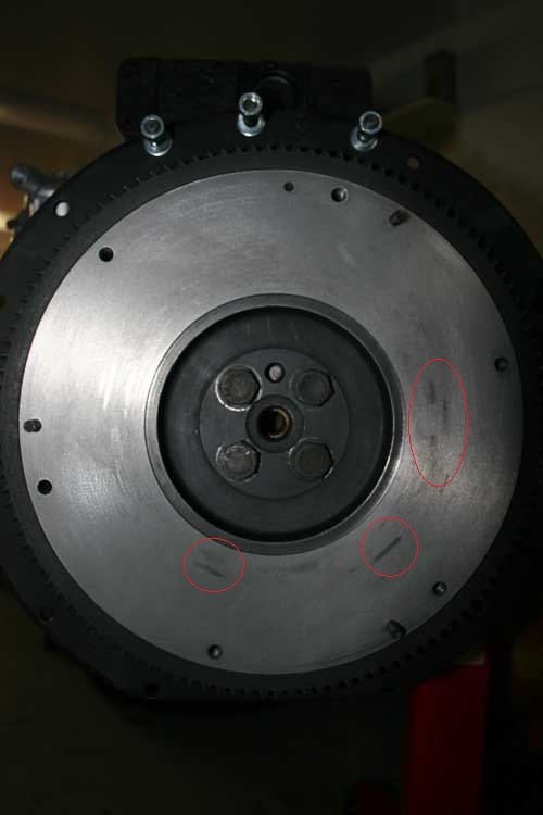
Also machined the fly wheel face which has some hard spots circled in red, could be poor material or work hardening you can just make them out in the photo, any way when i clocked the surface the hard spots were .02mm high which is ok.
IMG_4182a.jpg
18 Apr 2014, 11:59am
Nice work and glad to see the words Navigator on the coil cover and not the name of another ermmmm manufacturer!
18 Apr 2014, 2:17pm
Swifty - Your car is going to be full of really nice touches at this rate. :cool:

Good luck, Paul. :)
18 Apr 2014, 7:21pm
Thanks Viatron and Paul.

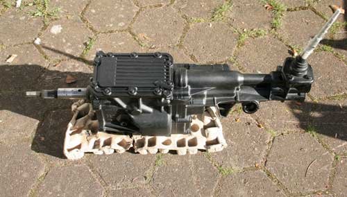
The type 9 gearbox has eventually arrived having been sent to Aberdeen by mistake and it looks good, all gears mesh with no chipped teeth. Its out of a Ford Capri with the longer input shaft to be able to reach the bush in the end of the crank shaft plus the gearing suits the GT6 engine better. I decided to go along this route as these gearboxes are reliable and pretty bullet proof with the fifth gear instead of the overdrive in the triumph box.

IMG_4229.jpg


Coated in zinc primer and a coat or two of epoxy chassis paint for good measure. It has the ally top cover which adds strength compared to the factory fitted pressed steel cover, short shift lever and an electronic speedo pick up sensor, will have to do some research for this and see what's available clocks wise etc.


IMG_42322.jpg
IMG_4233.jpg


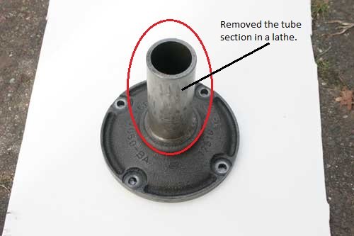
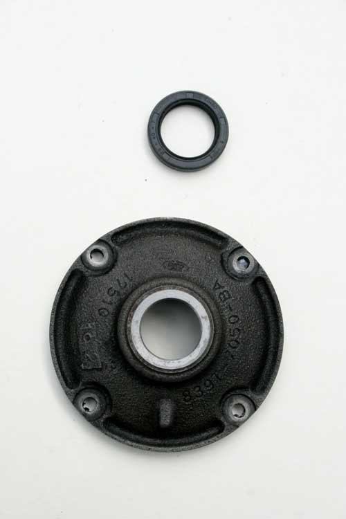
Removed the release bearing mount form the type 9 G/B and machined the tube section off as this interferes with the GT6 bell housing, left hand pic shows before and right hand pic shows after machining with a new lip seal ready to fit as it's a good time to replace seals etc.

Made a drawing for the adapter plate that will attach the type 9 gearbox to the GT6 bell housing, i need to source a clutch plate for a Capri to match up with the gearbox input shaft splines.

Also made some adjustments to the engine mounts to suit a GT6 engine, tacked welded on for now and tomorrow i will lift the engine in to the chassis to make sure all is correct then fully weld the brackets onto the chassis.
Well that's it for now, see you all soon.
19 Apr 2014, 6:46pm
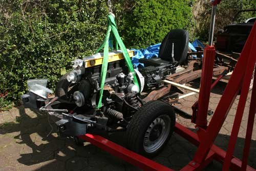
Today progress was good, managed to trial fit the engine and gearbox before welding the engine brackets fully, also checked out the seating position to see where the type 9 gear change is and it looks good. The seat is balanced on top of a few breeze blocks to give me an idea of height etc.


IMG_4234.jpg


Engine bolted in with the gearbox whilst using a piece of wood to support the rear of the gearbox, the engine has about a 3 degree tilt backwards which i assume is ok.

IMG_4237.jpg
IMG_4238.jpg


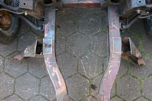
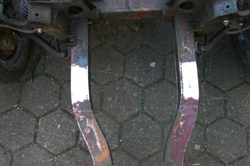
Removed the rotten front outriggers to weld in two new ones, i used a 1mm cutting disc in a angle grinder to carefully cut through the old rigger metal making sure i didn't go into the chassis, then ground back the old weld/rust ready to weld. Before removing the old riggers i took various measurements and angles to make sure the new ones are in the correct position.


IMG_4240.jpg
IMG_4242.jpg


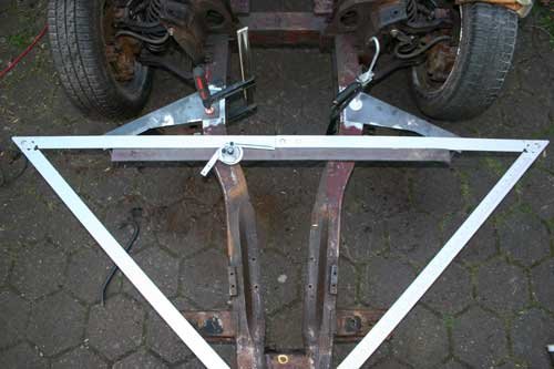
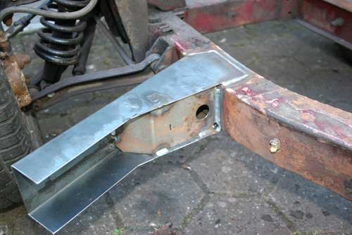
Lining up the new riggers using a large set square and tape measure double checking everything before i weld the riggers to the chassis. Finished article which went very well and will hopefully last another forty years.

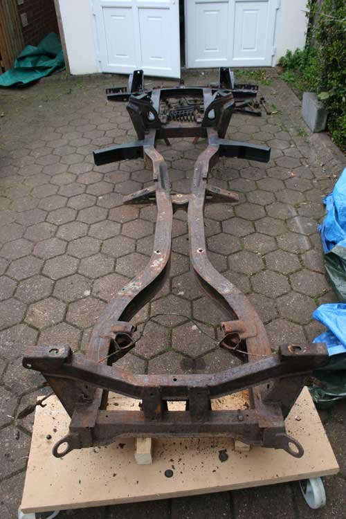
Well i am nearly at the stage to strip the chassis completely and send off to be shot blasted, will also send all the suspension parts and diff etc before overhauling them. I still haven't decided on which colour to paint the chassis i do fancy something different to the standard black.
Well time to go and if the weathers good tomorrow then i will progress the project further getting ever closer to the finally.

21 Apr 2014, 8:41am
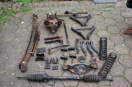
At last the chassis is ready for shot blasting with all bushes etc removed from the suspension parts so the dirty side of the build is coming to an end. The easiest way to remove the old bushes is by drilling the metal insert out which releases the rubber part of the bush. The diff requires new oil seals and the back lash is minimal with a 1.83:1 ratio, one thing that is evident the diff is an earlier version with six stud holes where as from a car of this age has four stud holes.

IMG_4278.jpg
IMG_4277.jpg


Chassis and parts ready for shot blasting.

Now looking around for parts to upgrade the brakes to GT6 standard, 8"x1.5" rear drums and larger front discs/calipers also fitting a remote servo possibly the Power Tune version. I may also have to change the front vertical links to suit a larger disc's but more home work required.
25 Apr 2014, 6:24pm
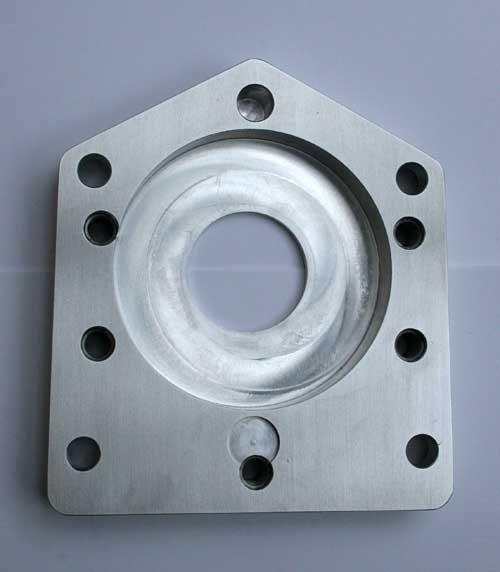
Finished the adapter plate to attach a ford type 9 gearbox to a GT6 engine. Will hopefully have time to fit it tomorrow.
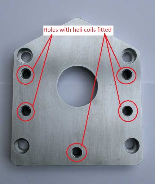
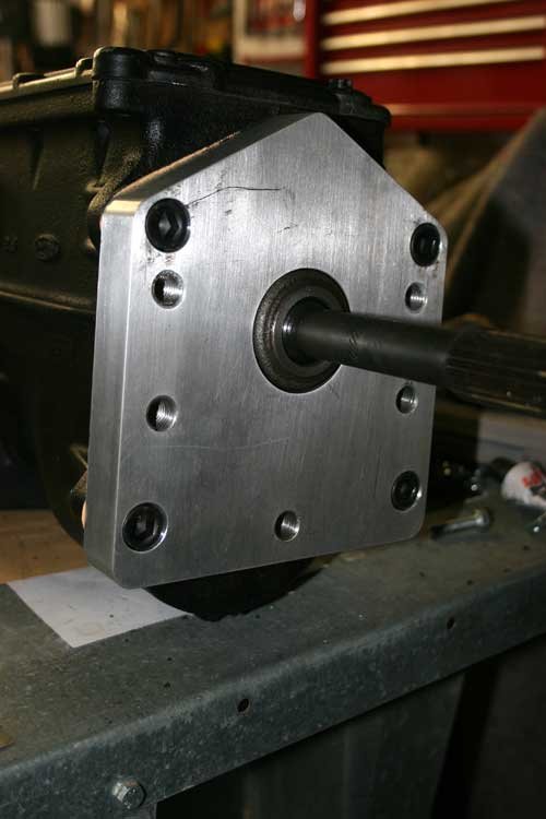
The threaded holes which fasten the bell housing onto the plate have been fitted with M12 x 1.75p heli coils for greater durability and high tensile cap head bolts will be used. Managed to buy locally at a very reasonable price four M12 x 1.5p high tensile cap head bolts which fasten the plate to the gearbox, ford sell these at the usual inflated price so it pays to check a local supplier first, i think i will also get a price for UNF nuts and bolts from these guys.


IMG_4283.jpg
IMG_4282.jpg


Saved a few quid again as these are about £90 to buy.
27 Apr 2014, 1:34pm
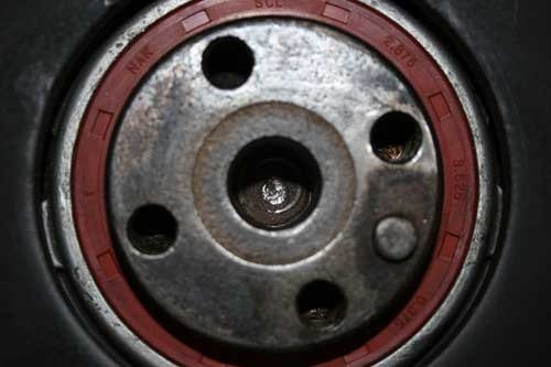
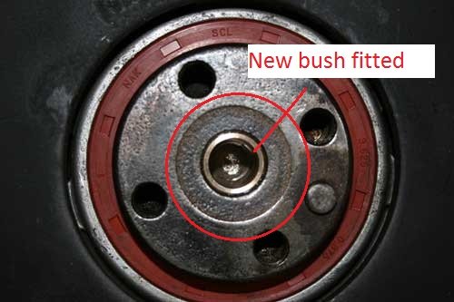
Fitted the adapter plate to the engine and gearbox and all went well, had to make a new phosphor bronze bush as the input shaft on the type 9 (15mm dia) is larger than the triumph gearbox input shaft.

IMG_4285.jpg
IMG_4286.jpg


Photo before and after of the crank shaft with a new bush fitted to suit the ford gearbox input shaft diameter of 15.02mm.


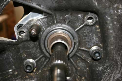
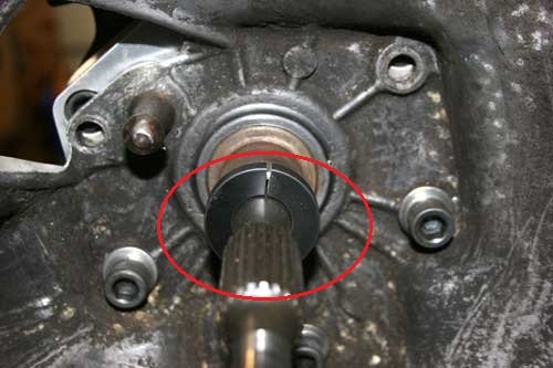
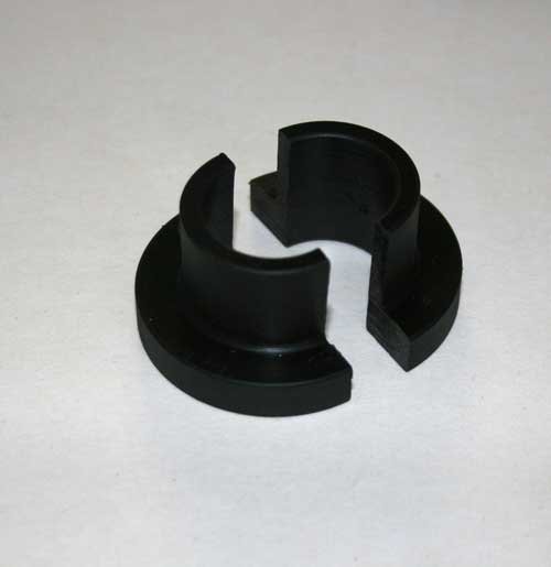
I had to come up with an idea to make sure the new gearbox and triumph bell housing were centrally aligned, so i made a split plastic bush to slide into the clutch release bearing shaft, it has to be split as the type 9 input shaft is 19.05mm dia but the spline section is 25mm dia, if that make sense any way here are a couple of pictures to show what i mean.

IMG_4288.jpg
IMG_4287.jpg


Fist picture shows no plastic bush fitted and second shows the bush in place circled in red. Once the bush is in place you can tighten the bell housing mount bolts up confident that all is aligned.

IMG_4292.jpg


Split alignment bush used to align bell housing with gearbox input shaft, made from plastic as it's easy to machine and cheap.
27 Apr 2014, 1:58pm
IMG_4293.jpg


Here you can see the adapter plate fitted to the type 9 gearbox, bolted on with four high tensile cap heads M12 x 1.5 pitch x 35mm which i bought from a local nut and bolt company for less then a quarter what ford charge. Paper gasket fitted between the gearbox and plate.

IMG_4294.jpg


Had to fettle the inside of the triumph bell housing slightly to allow the mount bolts to seat correctly, two new holes have to be drilled into the bell housing as the original top two mount holes are half way over the position of the type 9 gearbox mount holes. Circled in red the area slightly cut away by hand.

IMG_4296.jpg


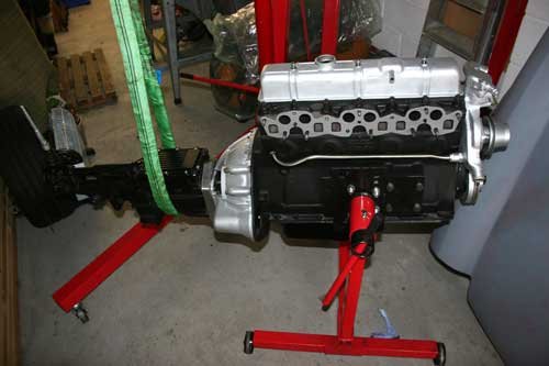
Gearbox correctly aligned and mounted onto the engine, supported by the sling as i don't trust the engine stand to hold both together, i have removed the gearbox for now until its ready to go into the chassis.

Well today the weather was rubbish so not much progress made, still waiting for the chassis to be shot blasted which is the next big thing to be done. Managed to snap up a full stainless exhaust system and high torque starter motor for a very good price so saved a few pennies again which is one of my life's missions.

See you all soon.
27 Apr 2014, 2:41pm
Swifty - More nice work going on here. :cool:

I am guessing that this is not your first car project. :icon_wink:

Good luck, Paul. :)
27 Apr 2014, 4:50pm
Hi Paul It's my first kit car project although i very nearly came close to starting a Dax Cobra build about four years ago after visiting many kit car shows but the total outlay to build a high spec cobra was way over what i felt was reasonable. I then moved onto a MGA but the price and availability of these cars made me think of another project.

I have completed a full nut and bolt restoration of a MGB back in the eighties and i suppose from that i caught the bug, i also have a great interest for all things mechanical and enjoy making parts etc for a car plus the banter and threads like yours on this forum made me take a harder look at a spitfire based project.

Cheers.:wink:
1 May 2014, 7:16pm
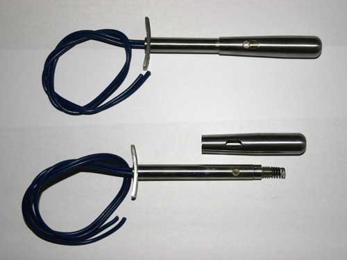
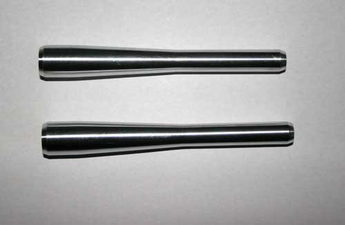
Not a lot to report made two indicator stalks out of stainless and two out of ally, the stainless stalks have a push switch for a horn or washer pump facility where as the ally stalks are solid, will wait and see which ones i will use.

I am thinking along the lines of shortening the original stalks and sliding the new ally ones onto the old stalks, may be glue with araldite or if i use the stainless stalks i will have to cut the old stalk off completely and attach the small plate to the indicator switch body which will be fun!!:smash:

IMG_4297.jpg
IMG_4298.jpg


The small push switch is behind the spring, machined a slot in the moving end to locate a nylon covered pin. The ally stalks are one piece with a 5mm dia x 50mm hole in one end to fit over the original triumph stalk.

The chassis is off to be shot blasted on Saturday so once back i can begin to replace the suspension parts etc and start to see something happening. Hopefully off to Stoneleigh this weekend to pick up a few goodies and see the Ribble guys.

See you all soon.
5 May 2014, 9:13am
I am now looking to buy a full chassis bush kit with bolts etc, can any one recommend a good source for these. Is the poly bush any better for the extra cost as this car will be a second vehicle, week end use.