MadaboutKitcars

This is a read-only archive of the old Madabout Kitcars forum. New posts and replies are no longer possible, but every thread is still here to browse and read.

Help with fuel tank flow plans and brake pipes please!

31 Oct 2011, 6:46pm
Sorton wrote:


Incidentally, I am intrigued by all the various fuel systems others have used and wonder if I am missing something. I intend to use the system as fitted to my donor which consists of an in tank pump/gauge unit with pick up filter and then a standard in line external filter feeding straight to the engine.

In order to accommodate the length of the pump unit I intend to extend a small section of the centre underside of the tank which will also act as a fuel sump.

Hopefully cheap and simple!


Hi Sorton
I had hoped to do exactly as you are proposing: however, although it was easy enough to add a sump to the tank, I could not work out a way to seal the fitting of the plastic pump/tank lid to my own aluminium tank. It is a screw thread, and I could not see how to make it seal with the aluminium tank.
If you can find a way, I think it is a much the best solution.

http://www.flickr.com/photos/mikes_bmw_marlin_cabrio/3460716446/in/set-72157617099808506/


How do you get photos off flickr in the desired size? As soon as i highlight the photo I want I lose the URL properties to be able to import on to this site? Anyone know how to do this?
31 Oct 2011, 6:52pm
Sorton - I modified my Cabrio fuel tank to have a small fuel sump and (in conjunction with an external pump & filter) works a treat. It certainly makes the rest of the fuel system plumbing alot neater and simpler and also avoids the requirement for a seperate swirl pot in the engine bay.

http://www.flickr.com/photos/marlin_bmw_cabrio/271637606/in/photostream
31 Oct 2011, 8:19pm
Sorton wrote:
The fuel specific copper tube I bought at Exeter show last year is fully marked with its spec so presumably, if the tester gets awkward, that is what he will be looking for.

Incidentally, I am intrigued by all the various fuel systems others have used and wonder if I am missing something. I intend to use the system as fitted to my donor which consists of an in tank pump/gauge unit with pick up filter and then a standard in line external filter feeding straight to the engine.

In order to accommodate the length of the pump unit I intend to extend a small section of the centre underside of the tank which will also act as a fuel sump.

Hopefully cheap and simple!


The various fuel system arrangements used by myself and the others are due to the standard tank not having a sump or baffles so if you can add those features it will be far simpler. In retrospect I wish that I had done so. Even paying someone to weld in a sump on the tank would have been cheaper that the two fuel pump/swirl pot arrangement that some of us ended up with.

It does work well though - never had any sign of starvation at the traffic light Grand Prix :-)

Next car will have carburettors - so much simpler.....

Robin
1 Nov 2011, 11:50am
Hmmmm! My tank is not fitted yet, it seems from reading this that it would be worth getting a sump welded in which would avoid surge starvation when fuel is low abd also add a fuel reserve in extremis. What then? just a single HP pump and filter with a LP return line to tank from the fuel rail?
Any ideas on size/design of sump?
John
1 Nov 2011, 12:51pm
oaktree11 wrote:
Hmmmm! My tank is not fitted yet, it seems from reading this that it would be worth getting a sump welded in which would avoid surge starvation when fuel is low abd also add a fuel reserve in extremis. What then? just a single HP pump and filter with a LP return line to tank from the fuel rail?
Any ideas on size/design of sump?
John


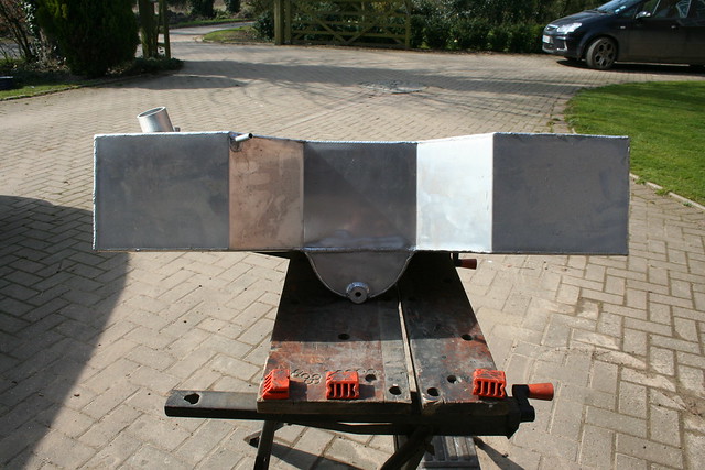
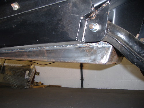
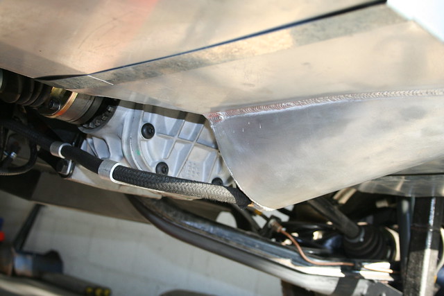
Mine was calculated to hold 2 litres, but I think the design is more important so that you can stop starvation when cornering, or accelerating hard with lower fuel levels. I also designed it to be behind the diff to protect it from road debris. I drilled 5 x 10mm diameter hole in the bottom of the tank and then welded the sump on. This ensures there can be very limited wash back in to the main tank.

If you go for a sump, you can do away with the whole low pressure primary feed system of low pressure pump and filter and swirl pot. I made my sump myself, and took it to the local fabricators who welded it up as a "cash" job very cheaply.


1 Nov 2011, 1:12pm
Thanks Mike - that really does look the business and it has to be good to cut down on the complication.
What did you do for HP pump and filter and locations?
Did you use flexi piping the whole way, and for the return line?
Thanks, John
1 Nov 2011, 1:53pm
oaktree11 wrote:
Thanks Mike - that really does look the business and it has to be good to cut down on the complication.
What did you do for HP pump and filter and locations?
Did you use flexi piping the whole way, and for the return line?
Thanks, John


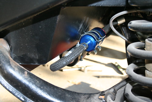
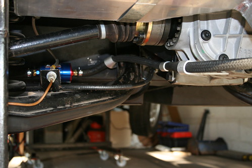
I spoke to Sytec who seem to know what they are talking about, and they advised getting the pump below the tank to ensure it never ran dry, as the pumps will fail very quickly if allowed to run dry.
It seemed sensible to me to have a filter between the tank and the high pressure pump, and then I used the donor filter after the pump and prior to the injection rail. (Not sure it will really do anything, but it can do no harm).
I have used copper pipe along the transmission tunnel for the high pressure and return, but will have to wait and see what they say at the IVA test, which is now at least on the horizon for next year.


Filter (Blue) above the high pressure pump. Since taking these photos I have been frightened in to replacing the flexible fuel pies with rubber pipes marked as suitable for use with fuel. If anyone fails IVA on the copper pipe before I submit mine I will have to follow suit then, but do not intend to otherwise.


My fuel pump is below the normal seat base, but I have made a 65mm seat recess in my floor to allow Audi A4 seats to be fitted. This recess then shields the pump totally from road debris.

1 Nov 2011, 5:29pm
Mike wrote:
I drilled 5 x 10mm diameter hole in the bottom of the tank and then welded the sump on. This ensures there can be very limited wash back in to the main tank.


Aha! I was wondering about that. And as John says, your sump really does look the business.

Mark.
1 Nov 2011, 8:09pm
mashtun wrote:
Aha! I was wondering about that. And as John says, your sump really does look the business.

Mark.


It was very easy to make. I rolled the profile through three rollers to get the basic curvature: then immersed it in a bucket of water at an angle to determine the line along which to trim it to fit the tank at the angle it is now. Then I made the half moon end. I took it along to my local engineering works at the weekend and gave the welder £10 to weld it all up, test it, and second weld the seams.
2 Nov 2011, 11:46am
You know what? this thread really illustrates the value of this (and other) forums. Thanks to you guys I have a lot more knowledge now not just theories but hard practical facts which I can develop and eventually feed back to the forum.
Thanks to everyone, I really appreciate it!
John