This is a read-only archive of the old Madabout Kitcars forum. New posts and replies are no longer possible, but every thread is still here to browse and read.
I'd like to add a note to the Dual servo thread for anyone get to fit their servo - I suspect there are quite a few who have left it until winter to do along with a list of other things.
Wide band O2 gauge and sensor with data logging (laptop connect with serial cable).
I know mines not fuelling right - the screw on the AFM was messed with before I got it. I should be able to tweak that with it a bit but its more peace of mind I'm after that it doesn't lean out at the top. It as suitable outputs to connect to after market ECU's like Megasquirt so that may be on the cards next...
Calibrated the sensor today, the big plastic plug that you connect to the sensor has a little plastic tab if you connect the plugs without lifting it then it can very easily go the wrong side of the plug. That stops it connecting up properly which this one did first few times I tried.
I put the power on with the sensor disconnected which puts it in calibration mode. Unplugged the power and plug in the lambda sensor then put the power back on. The sensor gets quite hot, you can see it glowing here inside:
It showed HTR on screen while it warmed up. My bench power supply showed between 1.4 and 1.7 amps being pulled while it was warming up.
It briefly showed CAL is the display while calibrating then switched to 22.4 as it is in free air:
Now ready to install when its dry enough to drive over to the garage with all the tools
The current clutch slave is about to pop, the mechanism for moving the clutch in and out appear to be overly stressing the hydraulic components.
As I’ll need to take the gearbox off anyway it seemed like a good time for an upgrade. Apparently the ZF 6 speed from the E46 320d is a straight fit and as a bonus the same angle as the M20, it's also a more solidly built and younger than the getrag that's in there now. Only down side is that I might need a different final drive ratio to make full use of the new ratios.
One eBay special later:
But the shift linkage at the top was smashed in transit
So decided to try and fit it using HTS 2000 brazing rods. I tired this with propane but it wasn’t hot enough. I instead got a can MAPP gas and a new burner from B&Q:
Putting a hold on the 6 speed box for now, it's more than 10cm longer than the existing so needs new gearbox mount and the drive shaft shortened. I'm going replace the damanged hydrualic parts of the E30 clutch system initally instead.
Service time! New oil – fully synthetic ester
Managed to avoid spilling anything on the ground for a change!
Being able to take the side off the engine bay really makes filter swaps easy!
Also done is 6 new spark plugs (they’re pretty cheap so why not!)
Found a minor vacuum leak so the idle is much better now.
Also tried installing the AFR guage but it's stuck on the HTr display and won't calibrate so there's some testing and messing to do with it.
Hi Patrick. Just browsing back through this thread I noticed that you have put the (Sierra?) rear brake proportioning valve across the bulkhead. It has a ball inside that rolls up an angled bore to limit the flow of fluid to the back wheels and on the Sierra is on the near side inner wing facing forwards, not across the car. The idea is that the harder you brake the more it rolls up the bore and restricts the outlet port, delaying the pressure build up in the rea wheel cylinders. If fitted across the car it it won't do this.
Meanwhile it's all looking very smart. I love those banjo fittings on the master cylinder. I will probably go that route when I do my proposed pedal box move during the coming winter months. Peter.
Hi Peter, thanks for the info. The valve is from the E30 donor car. I'll double check the orientation in the donor and adjust as needed.
Brakes passed SVA like this, front lock before the rears but I'd rather make sure I don't have any long term issues with the most important system in the car.
My jump leads didn't work - no continuity = useless jump leads. The copper was crimped and cut straight through at the factory. Trimmed and now soldered – much better.
Inside the rocker cover still looking very clean. Adjusted all the valve gaps to 0.25mm, glad there are only 12 valves to do! Most needed a little tweak. Also gave the oil spray bar a good clean out with brake cleaner while the cover was off.
The rocker gasket was a bit very second hand, I managed to get one in Basingstoke same day which was a pleasant suprise! It explains why there was some oil in the plug holes.
The clutch slave failed – not sure why, perhapse the master cylinder was a miss match or it was just a bad part. The reason is not so important.
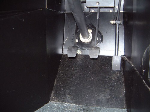
I’ve decided to use the BMW master cylinder as this will be matched to the slave. Unfortunatly the original design for the clutch attachment is very poor – the whole pedal box twists.
Therefore I’ve started protyping a new bracket design that will be a strong mount for the master cylinder with a bracket the bolts up through the top of the scuttle – already re-enforced for the pervious alternative clutch arrangment.
I’ll 3D print this bracket for test fitting and if it works OK I’ll try to recreate it in aluminum.
Since first installing the brakes a spring has been missing off one of the pads which means the passenger side calliper rattles. I decided to switch from the jurid to ATE pads – the ATE’s bite a bit better initally than the jurids – something I’ve found on my daily drivers. Also the ATE pads are OE for E46 / E9x.
A few bits of rust, here under the drivers door:
Chipped off, brushed and some rust remedy:
Sprayed with rollbar and chassis paint, you can see the hole in powder coat but I’d rather this than have the surface rust carry on creeping:
The wing mounts had also started to rust, so took these off while the wheels were off for the pad change. Also cleaned up any chips in the powder coat on the front suspension:
Refreshed with new nuts and bolts:
3D part has also finished printing, need to how this fits:
Clutch master fits on the 3D prototype print, there needs to be a bit more clearance for the fluid feed pipe, and it needs to be extended forward to make use of my second scuttle mount hole. I can probably add more re-enforcement.
Fits into the car too!
Added a hole for the scuttle mount:
A few cm forward of it is the second mount hole.
Need to make a few design tweaks then figure out how to make it out of metal.
Thanks Peter I'll see where the bite points end up with this setup - would be a good idea to add. With the worn out/broken setup the bite point was right at the bottom of the pedal which made it very difficult to drive, especially when the gearbox was cold.
We've got an Ultimaker 2+ the precision you get out of it is astounding - I modelled the the bolt holes 50mm apart and it fit perfectly. Not sure any of the materials we can print with would be strong enough for this application sadly - that would be perfect otherwise.
EDIT: hmm colorfabb have carbon fibre reinforced material, wonder how strong that is http://colorfabb.com/xt-cf20
V2 clutch bracket with room for pipe and holes to bolt to the top of the scuttle.
If this were printable as usable part then I’ve done an extra version with more structure and cleaned up edges – there would probably need to be more material to the front mount point as well:
Wow, this is getting exciting.
Are you planning to print it in wax and then create a plaster mould to make an alloy one?? (the age old 'lost wax' process)
Added a load of extra structure to strengthen the part were it’s bolted.
The print is sliced like this giving the most strength in the direction the force of pushing the clutch would go through the part.:
The yellow lines are the movement of the print head, the black cylinder is the print head, it's shown with the top 1/4 left to go, the corrigated stuff is support material - without it gravity can take effect and the runs of plastic can sag. It's set to print with 100% fill so that it's as strong as it can be. The prototype had less fill which saves both print time and plastic but is not as strong.
3D printing does take ages, especially with 100% fill, 10 hours in, 18 to go. With less fill it would print much faster, but then it would be a weaker piece (the yellow on the print bed is Kapton tape - printing this stuff to the glass will cause the glass to chip):
I snapped the head off my first clutch master cylinder input shaft (genuine donor BMW) before I ever got my car on the road, due to poor alignment with the clutch pedal.
What I eventually found was that master cylinder input shaft has a limited ability to accept the change in angle created by the clutch pedal passing through an arc. After 3/4 pedal travel the m/c input shaft began to bind on its own casing and further pedal movement generated a lateral force on the shaft which very quickly failed.
By trial and error I eventually found a new location where the master cylinder input shaft always remained within its own arc limits as the clutch pedal went through its full movement.
Since changing the alignment (touch wood!) it seems to operate really well, and I've had no more problems.
Thanks Mike - I'll check it out when it test fit the printed part. Unfortunately I ran out of filament before it was done but shoud be enough for testing. Need to order some more.
Ran out of ColorFabb HT with a bit to go on the print unfortunately, however this is a great strength test piece. It’s very strong already with 2/3 of the triangulation structure missing. This part will work in the car, no need to remake in metal.
I may make a few more design tweaks before starting another print. More material is due at the end of the week.