This is a read-only archive of the old Madabout Kitcars forum. New posts and replies are no longer possible, but every thread is still here to browse and read.
Nice work swifty. However that's so many gauges that people will think it's a cobra (or a sik wrex). Maybe I'm just jealous as I have the grand total of three, a speedo, fuel and temp gauge
Nice work swifty. However that's so many gauges that people will think it's a cobra (or a sik wrex). Maybe I'm just jealous as I have the grand total of a speedo and fuel gauge
What an incredibble nice build you have. I looked back at your thread with great intrest. Superb quality en detail. Would love to see you project finished. Keep up this good work with magnificent result.
andrewhush The bezel was bought off flea bay its for a 4 inch gauge. I've just noticed and you live very close to me, probably less than 5 miles.
1iTim Yes its a lot of gauges but after much debate it looked better with four small gauges, the center gauge will be a 125mm tacho, the rest of the holes are for the minimum amount of switch's and buttons.
christinedmc Thanks for the comment, i too would like to see your build so maybe who knows we may meet up at a show in the future.
Meeting at a show would be very nice. I visited Stoneleigh a month ago (but not with my Spyder). I saw one green Sammio though. I hope to attend some events in the UK with my Spyder in the future.
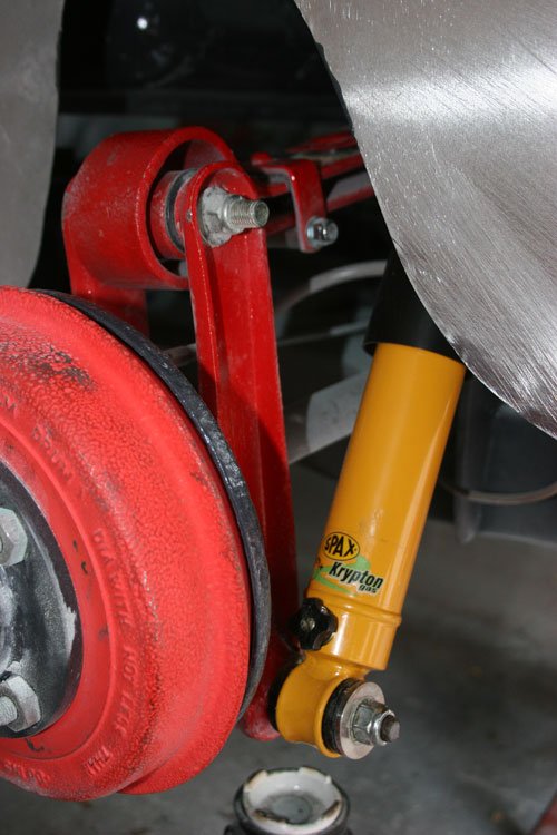
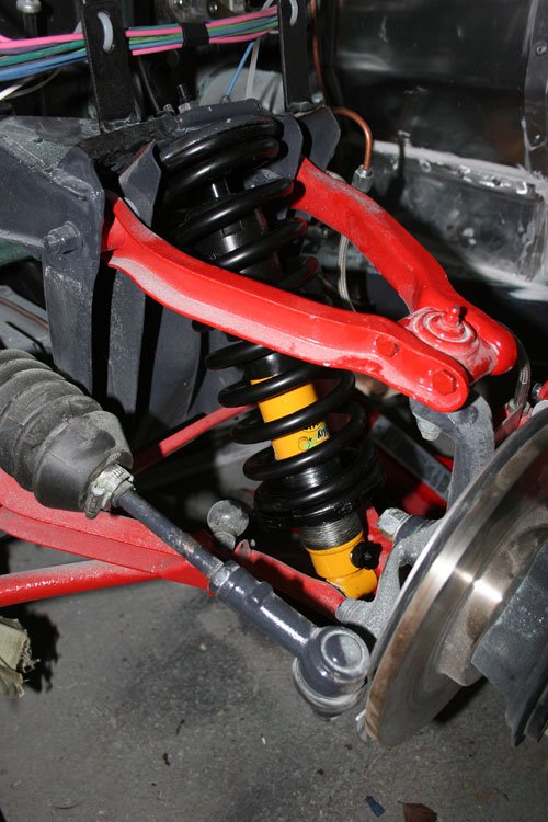
Today fitted the new shocks and springs to all four corners.
Rear and front parts fitted. The adjustment knob is easy to get to with the tyres fitted so making it easy to adjust the rebound in the future, there's 28 clicks from soft to hard so set them at mid way 14 clicks and will adjust once on the road.
The front height adjustment is set at half way until the car has been moved about and at the moment the front of the car is sitting about 30mm higher than with the standard springs etc so its looking good.
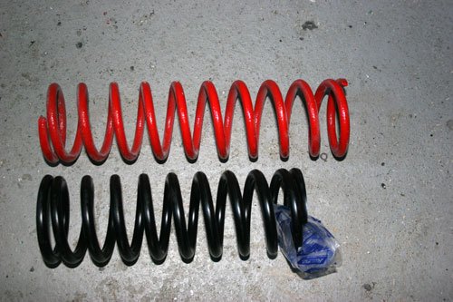
The original front springs in red are about 40mm longer than the uprated springs which made the new springs easier to fit than the standard springs, if you wind the adjustment rings down to the bottom then the top spring cup can be fitted without the need to compress the spring.
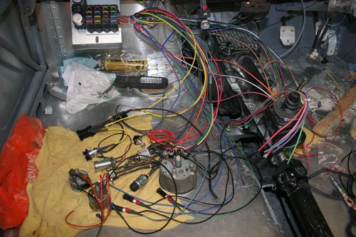
Grabbed a couple of mins today on the build to progress the wiring.
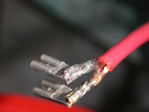
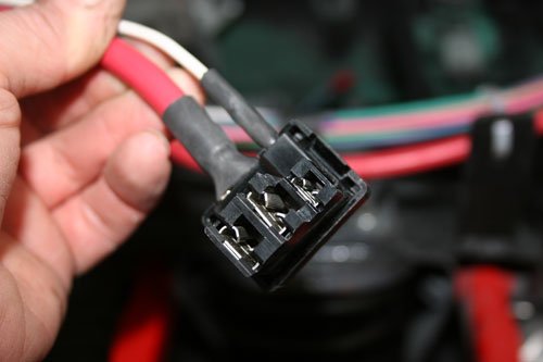
Used multi strand 10mm cable from the alternator charge post to the battery supply on the starter solenoid. The alternator i've fitted is a late Lucas type that has three connectors, two 10mm male spade's and one 6.3mm male spade, both 10mm's are connected together internally so i divided the cable end into two then soldered these to the 10mm female spade connectors for the charge circuit. The 6.3mm spade (white wire in pic) goes to the ign light on the dashboard, earlier Lucas alternators used the 6.3mm spade as the alternator exciter feed to start the charge current in the alternator.
Finished off with heat shrink wrap over the bare cable.
More or less what I did, it helps to spread the load. Up to 45 Amps through one connector is better as 22 Amps each through two.
How is your earth? A second earth strap is good insurance, they often crack many of the strands due to the work hardening of the copper. That can lead to bearing failure in the drive train if the starter load has to take that route.
I've fitted two separate earths to the engine and one to the gearbox for good measure, i usually over engineering things if i can and due to the fire hazard of a fiberglass body i though it wise to over compensate.
I've also welded studs to various points through out the car for the earthing of the lights and equipment.
Yes, with any chassied car earthing needs special attention, it's easy to become complacent with modern body shells but even with metal bodies the earthing of body to chassis can be iffy. I grew up with wooden framed metal bodies on a chassis, then Land Rovers which suffer badly from corrosion where the aluminium meets the steel.
I like the idea of welding studs to the chassis at strategic places. I weld a heavy steel lug to bolt the battery isolator to the chassis but other welded studs sounds a neat idea, thanks for that one!
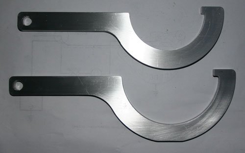
Been busy on the miller making a couple of C spanners to adjust the Spax front shock height, made from 6mm ally plate.
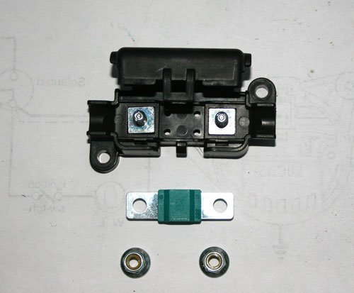
Today the Midi type car fuse holder arrived from flea bay, if you want one it's Here, also bought a few spare fuse's just in case.
The fuse size i've gone with is 40 amps, there are other sizes available.
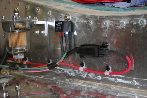
Its fitted to the bulk head taking the 12v supply from the battery post on the starter solenoid and feeds the main fuse board with 12v, it's basically an extra safety precautions for the fuse board.
The solenoid in the picture is for radiator fan supply, i may fit a small deflector plate above the midi fuse holder to prevent water ingress off the bonnet shut lip.
The next job is to wire in all the switches and clocks on the dash board along with fitting the coolant hoses so that i can run the engine.
Looking at how to get the best air filter solution for the twin 150 strombergs. Have thought about using a universal cone type filter with a fabricated box mounted to the carb intake, this way i can draw cool air away from the engine.
Looking for advice on any pit falls and useful web sites for information, so if anybody has experience with this type of filtration then let me know of your experiences.
Made a few more parts to tie up a couple of loose ends.
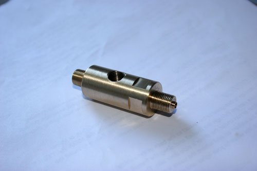
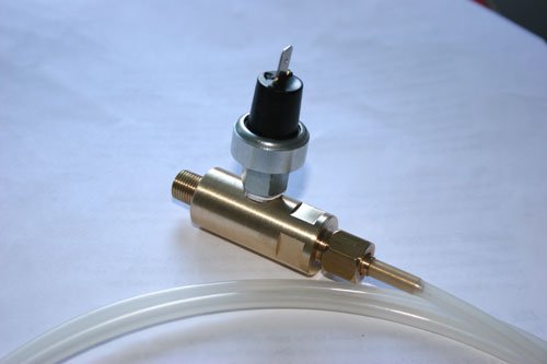
I am fitting an oil pressure gauge so require a T fitting so the oil feed to the mechanical gauge and electric pressure switch can be fitted together.
Turned on the lathe first then four flats machined on the miller with a dividing head, the threads are 1/4 BSP, the small turned end on the thread is used to locate the fiber washer for the pipe nut to seal against.
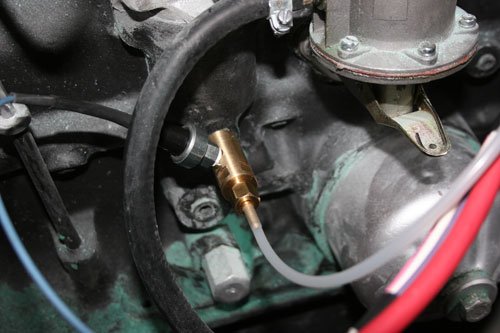
T piece fitted to block with pipe and pressure switch fitted.
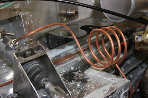
Have been debating if i should fit a flexi or solid pipe to the clutch for a number of weeks and decided to make a solid pipe with three coils to take up any vibration and help prevent work hardening, if it's good enough for the original spitfire then it's ok for me.
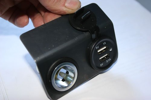
Made a small bracket out of 1.5mm steel plate for two power supply plug's that will be hidden behind the dashboard so as to not spoil the period look.
The standard cigarette lighter socket and a usb for phone charging.
Tomorrow i hope to have the wiring finished and for the lights etc to work.
Paul Will more than likely wait until the paint's done before the Mot.
Progressed the wiring over the last week and worked out what's required to mount the seats to the floor, just need to bend the ally sheet and do a little tig welding, will post pictures once complete.
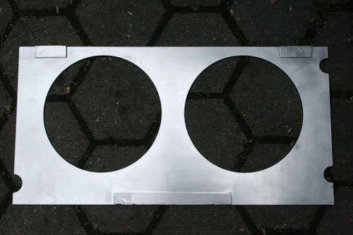
Also made a fan cowling template to mount the twin electric fans, will post pictures when finished.
For the air box iv'e decided to fabricate a removable box with mount plate mounted to the twin carbs and piped up with an induction tube fitted with a cone filter.
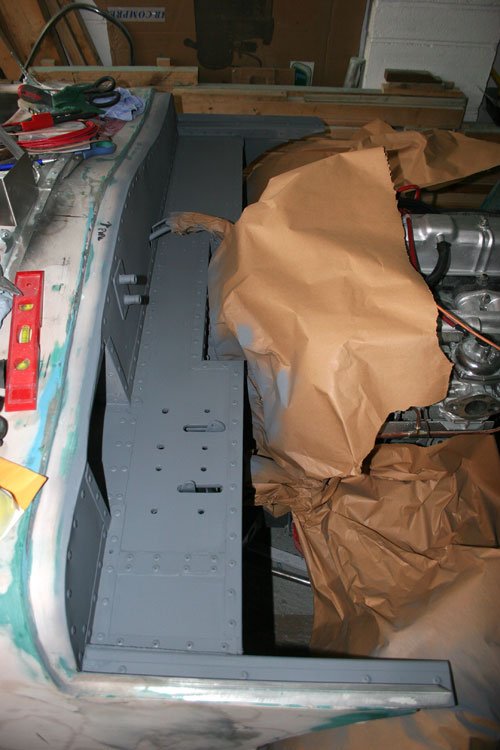
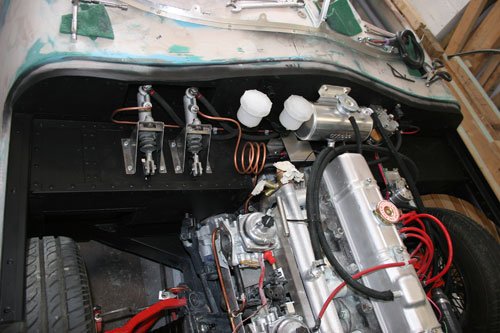
Removed all the components from the bulkhead to paint before finally bleeding the brakes and clutch, this will make life a little easier as it's a lot easier to remove the parts dry than after the bake fluid has been added.
Parts removed and surface keyed before undercoat applied.
Undercoat and final mat black paint applied. It now looks a lot more tidier, the bonnet shut line on the bulkhead will have a strip of foam to hide the paint transition line between the mat black and body colour.
I am now looking around for quotes to have all the ally parts I've made anodized to protect from the elements.
Beware of matt,it is a open paint and does not protect the metal iunderneath,also dirt will get into the paint and can't be removed,
Gloss has a laquer to protect the base colour,
On my Hotrod and trailer i used a satin black,almost matt but with a laquer and this cleans easy.
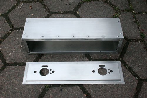
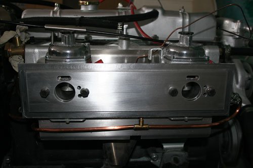
Fabricated the air box from 1mm ally sheet and 10 x 10 ally angle, also machined a back plate to mount the box to the carbs.
A small issue raised its head after the air box was fitted to the carbs, the bonnet would not close fully by about 10mm's, doooo so after various solutions were bandied about like chopping the air box, cutting a hole in the bonnet and fitting another tear drop bulge i've gone with lifting the bonnet at the front by 30mm this will also give the front valance a little more ground clearance for any speed humps and also gives more clearance around the engine so all in all more than one issue fixed.
Attachment “IMG_5417.jpg” from the original forum could not be reliably recovered.
Attachment could not be found in the archived database.
The first image shows the lifted front end while the second is before, the valance bottom edge is now in line with the front anti roll bar which is the lowest point under the car.
Attachment “IMG_5420.jpg” from the original forum could not be reliably recovered.
Radiator fan mount plate painted.
Attachment “IMG_5421.jpg” from the original forum could not be reliably recovered.
Twin fans mounted to new plate, I've left a 10mm gap between the radiator face and the fan mount plate, sealed around the edges with foam to help the fans draw air through the radiator rather than from the sides.
Attachment “IMG_5422.jpg” from the original forum could not be reliably recovered.
Attachment “IMG_5423.jpg” from the original forum could not be reliably recovered.
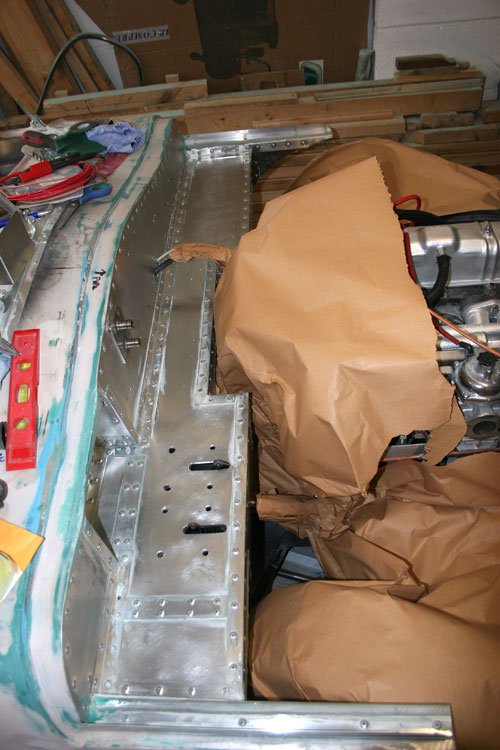
Seat mount folded with webs etc welded in place. Used 3mm ally sheet and will bolt through the floor section which has 3mm wall box section below, will also use stainless plate on top of the 3mm ally sheet where the bolts pass through. The seat is roughly in place for now, need to work out how to fill the gaps to each side of the seat between the ally sheet as the seat sides curve in over so there is about 20mm to fill.