This is a read-only archive of the old Madabout Kitcars forum. New posts and replies are no longer possible, but every thread is still here to browse and read.
Just a question about removing the output shaft to fit an extended one, does it just unscrew? Mine rotates but does not unscrew and there does not appear to be a locking ring? Am i missing something? John
John, I don,t think it is meant to be removed it can only be adjusted minimally as discussed in previous posts and may need you to make a modification as shown in one of Jasons posts (greatoldone) so that the two operating faces marry up. As Jason has said to me "In an ideal world and with all parts from the same manufacturer then all surfaces will marry up, but........we have a kit car and even then no two are the same"
The servo unit is a sealed one unlike the metro unit.
Hope that helps.
But check out Jasons previous posts for a solution, not the only one I am sure.
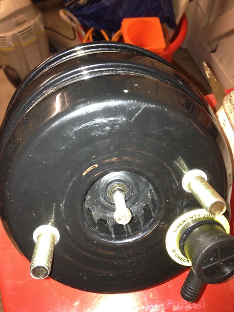
Hi John. Attached photo shows the plunger unscrewed from my actuating rod. To do this I fitted the servo assembly loosely into the car, then wedged the pedal down so the plunger protruded out of the housing. Then with a 6mm and 10mm ring spanner I undid the locknut and removed the screw. It wasn’t very tight.
Note! Only use spanners. Don’t attempt to grip the plunger itself with mole grips as it is a vacuum seal surface for the centre rubber seal.
As I don’t have a lathe I am using a pillar drill and ingenuity to make a longer extension plunger to replace the removed part similar to GreatOldOne’s Thread 353 Page 18, but with the 10mm diameter part made separately with a 6x15mm deep threaded hole in it. This will accept a 6mm x 40mm thread cut from a high tensile bolt to maximise strength. The two will be secured together with thread lock liquid. I can use the original lock nut when fitting to the servo rod. Peter.
oaktree11 wrote:
Just a question about removing the output shaft to fit an extended one, does it just unscrew? Mine rotates but does not unscrew and there does not appear to be a locking ring? Am i missing something? John
Thanks Peter and Dennis. I see how it all works now and have removed the output shaft.
Obviously, the lathe solution is ideal but we dont all have
access (actually i do own one, a Myford Super 7 but no space for it - its all full of car bits!) and I think Peter's idea is sound. This is not an area with huge loading but obviously it IS safety critical so wants to be well engineered. Actually, with the spacer plate in place the shaft will almost adjust enough for me....but not quite!
Another question! My MC has lugs that will take an M10 bolt. Has anyone fitted M10 machine countersunk bolts to the adaptor plate?
Servo in at last and just trying the master cylinder in place to check the pipe runs. BUT I seem to have discovered an alarming latent error from build. My understanding of the Sierra dual braking circuit is that the single output pipe from the rear (primary) piston goes to the rear brakes where it divides at the axle. The two output pipes from the front (secondary) piston each go to one front brake. That way if the rear fails you still have the front brakes and vice versa. Does everyone agree? With my system the rear brake pipe goes to one of the front cylinder outlets! Pipes were identified to M/C before disassembly and lengths are different so not an eror by me. Would appreciate any confirmation / comments before I do some major re-routing of the m/c connections to correct this. Peter.
That is a big no no IMHO. The split system off one chamber is always seperate circuits to the fronts and the single outlet goes to the rear to be "T'd".
If you think about it the way yours is plumbed you stand the chance of losing the rears and one front all at once which is a scary thought...
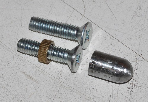
My solution to the problem of getting the servo push rod to work with the M/C plunger
The countersink M6 screw replaces the one supplied in the end of the servo pushrod but the little collet is retained to help prevent vibration slowly screwing it in further. I also had to grind the edge of the screw head a little to get it down to 10mm diameter so it will run smoothly up inside the M/C (compare with the unmolested screw above it)
The bullet was ground to shape from the shank of the M10 bolt I chopped out of the pedal box that was welded in as the accelerator pivot. It has a flat base for the screw to push on.
I had tried to use a much longer bullet with an M6 thread cut down the centre so I could screw some threaded rod in to mate with the servo directly but without a lathe and using a cheap clarke drill press, this is pretty difficult at this scale and I struggle to centre the hole, hence this solution.
It feels pretty solid when pushing the pedal.
One thing I have noticed with the new servo (even without the M/C installed) is that I get a slight clunk when you first push down and then it runs smoothly. it may be because my clevis pin is currently in loose as I'm going to replace with an M10 bolt but I wondered if anyone else had experienced this?
That is a big no no IMHO. The split system off one chamber is always seperate circuits to the fronts and the single outlet goes to the rear to be "T'd".
If you think about it the way yours is plumbed you stand the chance of losing the rears and one front all at once which is a scary thought...
John
Yup! That's what I thought. If the rears had failed it would have given me just one front brake = up the bank, or into oncoming traffic! Scary or what. Good job I found it now.
Attached is the servo plunger made on my small drill press today :-) Peter.
Pete (V8), that's essentially what I was trying to achieve but with the bullet bit being pretty much the entire length. You must have a better drill press vice than me as I can never get an accurate centre to do this kind of fine work. mine tends to push the piece out of alignment as you tighten it up
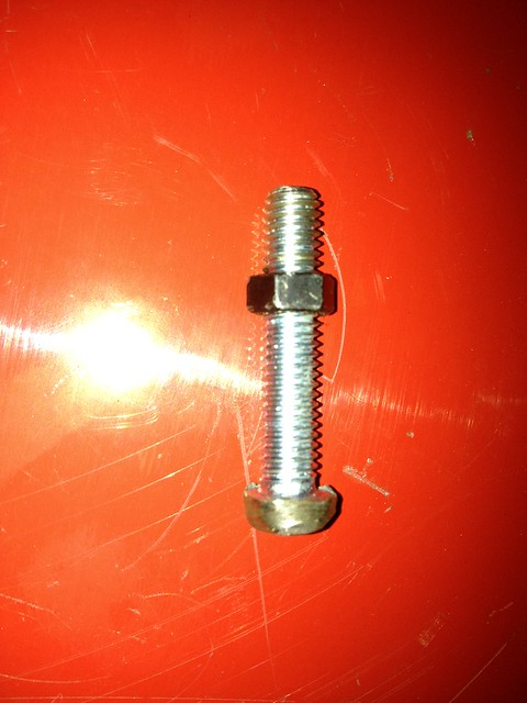
hmmmm am I being too simplistic or will and M6 bolt with the head ground to a button work just as well as a fabricated part. I had a bash a short while ago (until the cold got to me) and this is what it looks like. I will tidy it up tomorrow - I think it will work fine? - John
Yes, that would work - it's essentially what I did with the trial servo. I just cut the end off an M6 bolt and re-used the spacer / cap I already had for use with the metro servo.
Top tip - if you want the head of the bolt to be symetical, mount it in your drill and spin it as you offer it up to the grinding wheel. I did this when I ground the head down on the carriage bolt for my iPod mount. Works great.
Goo, now that IS a top tip! Actually I used a spare drill chuck to hold the bolt in but i didnt think of actually spinning it in a drill, thanks, mkII will follow tomorrow. John
Despite a whole succession of unscheduled events lately that have impinged on this project I have finally fitted the dual servo unit, and very smart it looks too! For anyone else who also has the older (straight) pedal box I can confirm that the packing washers are still required to offset the servo inwards. There is approximately 6mm total pack on each of the two outer studs. This still provides minimal clearance with the bonnet side panel junction which will need a bit of careful fettling to make it all clear. I have made a neat seal around the pedal box-to-bulkhead using black silicone sealant. I finally tracked this down at Screwfix (Cat No 90574). I have also made up a cover plate for the two access holes under the pedal box as none existed before and would have let engine bay fumes into the interior :-(
I have noticed that as there are two diaphragms (and presumably two separate in-line push rods) there is more pedal travel before the front actuating plunger starts to move, compared with the old Metro one. I have also made a new bracket to raise my remote fluid reservoir another 12mm higher to retain sufficient head above the front piston.
Peter.
Hmmmm.I dont have the bodywork yet and i Thought when I completed the trial fitment that it looks a bit close to the edge!
I was not aware that this had been an issue in the past or about the packing washers. Have you any pics?
If necessary it wont be a problem to do, I guess that it only changes the line of action of the pushrod minimally?
John
Hi John. I don't have any meaningful pics of the washers and it is now all covered up by the silicone sealant. However the washers should only be needed with an old style pedal box which has a front face parallel to the bulkhead. I understand from Mike that the later ones had the front face at an angle, so the packing washers are theoretically no longer required. With the washers in place on my servo mounting, the push rod lines up with the original assymetric pedal bolt like Marlin built it. This means that my new clevis is still all on one side of the pedal (with a spacer fitted between the legs to prevent them squeezing together). In the future I would like to make an offset link as illustrated in an earlier forum post. Regarding alignment of the push rod I guess that my clevis would have fitted either side of the pedal if it hadn't been neccessary to offset the servo to clear the bonnet edge. Peter.
Thanks very much for the information. Its a bit difficult to judge without the bodywork in place. Its snowing right now and the garage is freezing but I will venture out there soon and take a photo looking down to see what you all think.
Its a fairly crude linkage system and if it needs angling I dont think it would be a problem.
John
I have noticed that as there are two diaphragms (and presumably two separate in-line push rods) there is more pedal travel before the front actuating plunger starts to move, compared with the old Metro one.
Peter.
Peter
You are right.
I have a spare servo left over, and have just checked that the rear pushrod has to be actuated around 2mm before the front one begins to push against the M/C.
Mike
Thanks very much for the information. Its a bit difficult to judge without the bodywork in place. Its snowing right now and the garage is freezing but I will venture out there soon and take a photo looking down to see what you all think.
Its a fairly crude linkage system and if it needs angling I dont think it would be a problem.
John
Hi John
The entire system can be sub assembled in the warmth of your house. So you can check out the angles of the servo/pushrod/clevis in the kitchen to ensure it all line s up.
Then you'll have to brave the snow to test the clearance to the bonnet side wall. But this should not be a problem if you have the angled pedal box, as shown below by Peterux.
Mike
PS. I posted the M/C to remote elbows today.
Andrew Curtis called me this afternoon, on a real high, to say how thrilled he is with the new Dual 7" servo in his BMW Sportster set up. He is another person who says it has "transformed" his car.
Whilst Andrew's call echoed GOO's comments, and those of Alan Hogg, the difference this time is that Andrew has access to a disused airfield behind his farm, so he has been out and conducted some "semi-scientific" tests. The results were quite startling.
Travelling at a constant 70mph, he braked at a fixed marker point, and measured the travel distance before coming to a complete stop.
The average stopping distance of the 4 tests with the original Metro servo was 210 feet, braking as hard as he could.
Under the same conditions with the new Dual 7" servo the average distance was 103 feet, without having to try as hard.
Out of interest Andrew then tried to brake as though in an emergency, standing on the brakes: the front wheels could be made to lock upand the stopping distance was 85 feet.
This latter test was a one off though as he did not care to waste his tyres, but felt he knew now there was a point at which the wheels would lock up at the front.
Not only is he thrilled with the improvement in stopping distance, but with the 'feel' that he now has too. He feels he can brake hard in control without excessive pressure. The emrgency stop required significant effort, and he did not happen without knowing that he was braking very hard. In an absolute emergency it was possible to make the brakes slow the car to its maximum if required.
These are the first empirical tests which actually put numbers to the improvement we anticipated for the benefits of changing the Metro servo for the Dual 7" servo.
Andrew has fitted the Ford 22mm master cylinder, with standard BMW brake components, and piped it up as per his original set up, with only two outlets being used: one to the rear, and on to the front.
He was so pleased he wanted to tell everyone how good it is!! And to thank everyone involved in bringing the project about.
I am obviously pleased for Andrew, and it confirms what GOO has experienced is now being repeated by others, both in the Ford and BMW set ups.
It is interesting he made the oft repeated decision to buy a new Metro servo as he felt his old one must have been under performing! How manyof us have gone round that circle?
For the rest of us with cars still to be put on the road, and who will never experience the limitations of the Metro servo performance, I think this shows it has been a very worthwhile upgrade: and at a very reasonable cost.
Many thanks to all who have been involved and offered encouragement or joined the project to help make it happen.
Hopefully this brings the quest for better brakes to an end.
For the rest of us with cars still to be put on the road, and who will never experience the limitations of the Metro servo performance, I think this shows it has been a very worthwhile upgrade: and at a very reasonable cost.
Many thanks to all who have been involved and offered encouragement or joined the project to help make it happen.
Hopefully this brings the quest for better brakes to an end.
Mike
And not without a great deal of time and effort from you Mike as well. Not only the ordering and shipment of the servos but also the design and fabrication of the adaptor plate. Many, many thanks. It's greatly appreciated. But I hope I never have the occasion to truly benefit from all your efforts..........
Travelling at a constant 70mph, he braked at a fixed marker point, and measured the travel distance before coming to a complete stop.
The average stopping distance of the 4 tests with the original Metro servo was 210 feet, braking as hard as he could.
Under the same conditions with the new Dual 7" servo the average distance was 103 feet, without having to try as hard.
Mike
That is quite a remarkable result and clearly makes these cars much safer to drive.
I can't wait to try mine out with my new engine, as well. I'm currently overhauling my front suspension and will then move on to the brake servo.