MadaboutKitcars

This is a read-only archive of the old Madabout Kitcars forum. New posts and replies are no longer possible, but every thread is still here to browse and read.

Swifty's Navigator

9 May 2015, 5:30am
1iTim wrote:
Swiftly you are doing beautiful work!


Seconded! Could you do a rough guide to making billet ally knobs/rings (ooer) for those of us who have no idea how you magic up such special looking bits 'n' bobs?

Agree about the digital milometer spoiling the electric speedometers that are available btw. Smiths do a lovely 120mm classic speedo with matching tach, that I rather fancied for a Tribute SWB, but the speedo has a bright green lcd trip meter on full view. I suppose it could be carefully covered up with a strip of plastic/card with an old fashioned analogue version printed on it...


http://www.holden.co.uk/displayproducts.asp?sg=2&pgCode=070&sgName=Hardware&pgName=Gauges&agCode=0602&agName=Smiths+Classic+120mm+Gauges
9 May 2015, 7:30pm
Mr T that's the rev counter i am fitting, its 120mm which will look good on the dash but the speedo is only available as an electronic version so i'm looking at fitting the smiths classic 100mm mechanical which means i have had to workout the correct ratio for the type 9 gearbox with a spitfire diff and mgb wheels/tyres.
The guys on Rods and Sods were very helpful.

You need the diff ratio, the tyre Turns Per Mile or TPM and the speedo output ratio in relation to the gearbox output shaft.

My calculation is as follows
Diff ratio 3.89:1
TPM 833.5 on 185 x 70 x 14 tyre's
Gearbox output/speedo output ratio 2.875:1

The above info was used as follows to calculate the correct mechanical speedo gearing

833.5 x 3.89 = 3242.3 ÷ 2.875 = 1127.76

So i need to have a speedo re-calibrated with a gear ratio of 1127 or 1100.

I regards to how i made the knobs etc i manually turned on a lathe each one from a piece of 30mm dia round ally bar to the finished diameters of 25mm with a 10mm spigot drilled and tapped to suit the thread on the switch shaft body, put a 45 degree chamfer on the edges.

Transferred the turned parts to a vertical miller using a dividing head to index the turned part around to get the correct divisional points to machine the detail around the outer circumference, the job was held vertically for the undercut detail and horizontally in the dividing head for the dimpling detail with a spot drill. If you google how to use a dividing head in you tube you will see whats involved, it's a pretty basic engineering technique. Basically the dividing head takes 40 full turns to move the part 360 degrees so you first need to know how many divisions are required then divide by 40, for example i have 8 points on each knob that required machining so 40 ÷ 8 = 5 full turns but like i have already said i you want to see how the dividing head works then pay you tube a visit and all will be revealed.


Well that's it for now see you all soon.
10 May 2015, 6:03pm
Swifty - Something told me you weren't gripping these parts between your feet while using a hand drill. :icon_wink:

I'm really looking forward to seeing how your dash turns finally out, as it should look very special. :cool:

Good luck, Paul. :)
10 May 2015, 7:38pm
Yep, thanks for the explanation. Although I trained as an RAF engineering technician, it was for front-line operational engineering so it was all hand tools as you can't really ship a machine shop into the middle of a battle. We had a separate trade that dealt with workshop tooling, like lathes and sh!t.

Anyway, keep up the good work, it'll be good to see another Sammio on the road. :)
11 May 2015, 9:24pm
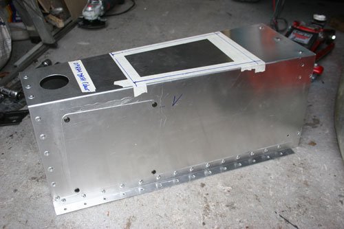
Was about to fix the gearbox tunnel to the floor when i thought that a few inspection holes with covers would be a good idea for future maintenance.

IMG_5319.jpg


One large inspection hole beside the reversing light switch and the speedo take off point on the drivers side and a smaller one opposite the oil level plug on the passenger side.


Well that's it for now see you all soon.
11 May 2015, 10:07pm
Great idea swifty I'll try to remember that when I get to that point
13 May 2015, 7:31pm
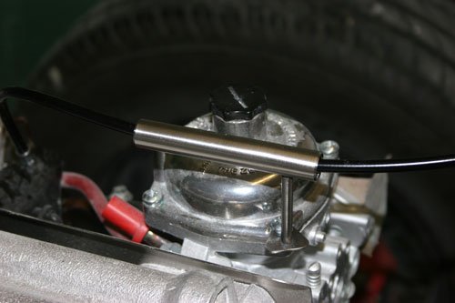
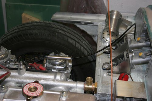
The throttle cable arrived today which when fitted stood quite high above the closed bonnet line so i decided to make a bracket to hold the cable lower in the engine bay.


IMG_5322.jpg
IMG_5323.jpg


Made from 10mm stainless tube with a length of 4mm rod and a small foot plate to attach through the carburetor diaphragm lid screw, tig welded together.

The cable now sits below the closed bonnet line without any sharp bends in a controlled manner for future safety.


Well that's it for now see you all soon.
14 May 2015, 5:43am
Swifty - Another neat job. :cool:

Plus I will now add checking where my throttle cable sits to my "To Do" list.

Good luck, Paul. :)
15 May 2015, 4:01pm
I've been adding inspection covers as I need them rather than try and pre-plan them. (on purpose of course :eusa_liar: )
In case it helps, so far I've needed ones for the speedo cable/gearbox oil, and one either side to get to the inside of my door hinges.
17 May 2015, 7:38am
Cheers guys.

I don't think you can have to many inspections covers which will make your life easier later on and save having to strip many parts off to get to a level plug etc.

Yesterday i started to layout and fix various parts to the bulkhead before removing for painting, will post pictures today of the bulkhead.


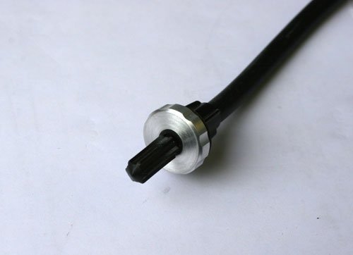
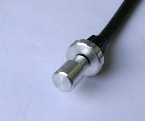
The second hand speedo arrived this week so i decided to turn an ally knob and fastening ring for the trip reset to match the other knobs made earlier.


IMG_5325.jpg
IMG_5326.jpg


The original is black plastic so i've basically turned a part to push onto the plastic knob as an interference fit. The fastening ring has an internal thread which tightens onto the dash holding the cable in place.


IMG_5333.jpg
IMG_5329.jpg


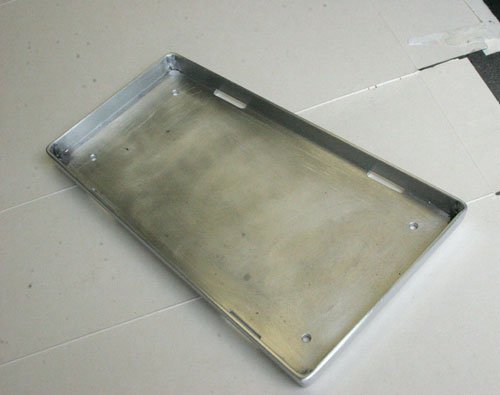
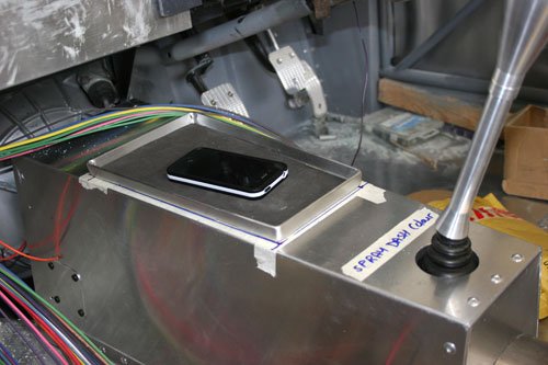
Fabricated a tray from 2mm ally sheet shaped to follow the gearbox tunnel. Folded the edges up to 6 degree angle and tig welded the four corners, machined four slots along the outer edge to act as drain holes in case it gets rained on which will more than likely happen. I had some thin foam draw liner from a tool box which cut to shape looks goods and stops things sliding around.

Quite a useful tray for the mobile phone etc, will put a 12v outlet socket hidden behind the dash board just above the tray in case the phone or sat nav needs power.


IMG_5324.jpg


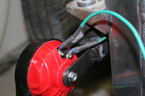
Started to connect various things to the wiring loom starting at the front, before a connector is crimped to the cable i slid a short length of heat shrink wrap onto the cable then pushed back over the crimped terminal and heat shrinked in place which helps to prevent water getting into the connector and also looks more professional, my intentions are to wrap the cable in black tape once all is connected.


Well that's it for now see you all soon.
17 May 2015, 8:05am
Swifty, I take it that's the horn? If so I think you may get a nicer note from it if you use a thinner bracket or perhaps a laminated one made from two layers of very thin spring steel or perhaps 0.6 stainless?

Just a thought...

I admire your ability to turn things up at the drop of a hat. Looking at your posts makes me regret the loss of my machines when I had to give up my workshop. I had a big (4 ton) Cincinnati vertical mill and a couple of Colchester lathes with all the tooling. All gone now, sadly. I can still use my buddies machines but they are thirty odd miles away... I love turning. Enjoy!
17 May 2015, 8:06am
swifty wrote:
... before a connector is crimped to the cable i slid a short length of heat shrink wrap onto the cable then pushed back over the crimped terminal and heat shrinked in place which helps to prevent water getting into the connector and also looks more professional...


Great tip. :cool:
17 May 2015, 8:54am
Paul L wrote:
Great tip. :cool:


Apart from the neatness, if a stray strand of wire missed being crimped into the fitting protects it from causing a short circuit to another connector or earthing and possibly blowing a fuse or worse.
17 May 2015, 12:36pm
8 Valve Ed I never gave the horn bracket a thought, the bracket that came with the horn is 2mm mild steel while the brackets i welded to the frame are 1/8" thick so i think i will do a little experimenting as i have gone for the twin high and low note disc horns for a distinctive sound so cheers on that one.

You must of had a large workshop to house a 4 ton vert mill and a couple of colchesters, one of the lathe's i use is a Dean Smith and Grace which i think date's from the mid fifties but still turns out accurate work with the addition of a DRO for laziness but i can honestly say some of these modern lathes are not a patch on the old boys.
I like the manual lathes for the small items I've machined as it gives me the freedom to do a simple sketch then turn as required without being tied up on the tolerances and if its not right i can go back and alter at will.
18 May 2015, 6:32am
As promised a photo of the bulkhead with parts mounted.

IMG_5340.jpg


The brake pipe needs a few clips fitting and also still to fit various rubber pipes for the fuel filter, header tank and oil catch tank.
The brake/clutch remote reservoir mount bracket has been powder coated black by a local company to see the quality of work before they coat the dash board etc. The bulkhead will be sprayed the same colour as the body to protect the ally sheet.


IMG_5334.jpg


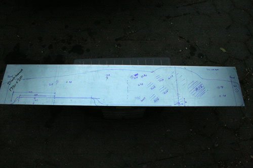
Now that i've decided on what clock's and switch's to fit ive marked out the dash panel made from 3mm ally sheet. The holes will be machined in as circular profile's on the cnc vert miller .5mm larger than the clock body diameter.


Well that's it for now see you soon.
27 May 2015, 6:02pm
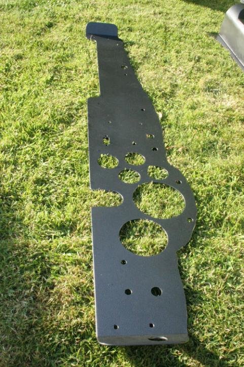
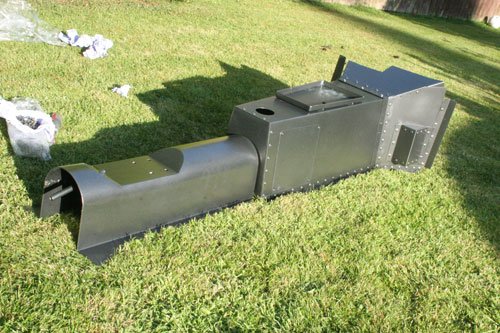
Not much progress made of late, machined the holes in the dash for the clocks and switch gear etc so today i dropped the dash, handbrake mount tunnel and gearbox tunnel off to be powder coated in a black/grey textured paint all for £45 which i think is VFM.

Progressed the wiring harness some more but apart from that not a lot of progress made.

Well see you all soon.
27 May 2015, 7:50pm
swifty wrote:
8 Valve Ed I never gave the horn bracket a thought, the bracket that came with the horn is 2mm mild steel while the brackets i welded to the frame are 1/8" thick so i think i will do a little experimenting as i have gone for the twin high and low note disc horns for a distinctive sound so cheers on that one.

You must of had a large workshop to house a 4 ton vert mill and a couple of colchesters, one of the lathe's i use is a Dean Smith and Grace which i think date's from the mid fifties but still turns out accurate work with the addition of a DRO for laziness but i can honestly say some of these modern lathes are not a patch on the old boys.
I like the manual lathes for the small items I've machined as it gives me the freedom to do a simple sketch then turn as required without being tied up on the tolerances and if its not right i can go back and alter at will.


Hi nearly missed this, been a bit distracted with software updates...

Yes, I had a great workshop, The firm I worked for were builders but because of my tenancy towards metal, I was allowed to equip my own workshop and I used it to innovate for the building side, I built all sorts of specialised equipment for underpinning buildings and drilling rock in difficult locations, rippers and specialised joinery tooling, to mention but a few. Unfortunately I have few photo's from those days.

The Cincinnati could drill a 50mm hole in one pass through 75mm boiler plate without even flinching. I had a little Denby flat belt driven horizontal mill too, that ended up as a rolling mill to curve large (75mm sq) box section to fabricate curved railings. I had a few diggers too.

I have decided if my host who is letting me use his shed, will allow, I hope to get my own lathe later this year. I have the free use of two but they are thirty and fifty miles away, I need to arrange access at mutually convenient times and there is the ever present risk of me breaking somebody else's (expensive) tooling. I need to be able to pop a chunk of metal in the chuck and turn it there and then. There are so many occasions I would have used a lathe during my Berlinetta restoration had one been readily available.

I am used to Colchesters, my friends is an old Harrison, I find the small headstock hole very restrictive, I think it's only 14mm and it only has an MT2 tailstock taper despite being quite a large and heavy lathe.

I need at least 25mm through the head with an MT3 tailstock. Min 150 throw and 600 between centres. I have been looking on eBay and there seem to be plenty with tooling and chucks well below £700.

I want to be able to turn rollers for a swaging machine/jenny (bead roller) The next phase of my build will hopefully involve replacing most or all of the GRP panels with aluminium.
4 Jun 2015, 6:28am
Yesterday i collected the powder coated parts which have turned out great, now need to try and not chip the coated parts.

IMG_5368.jpg
IMG_5365.jpg


Dashboard and gearbox tunnel.


IMG_5373.jpg
IMG_5370.jpg


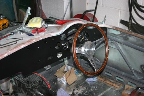
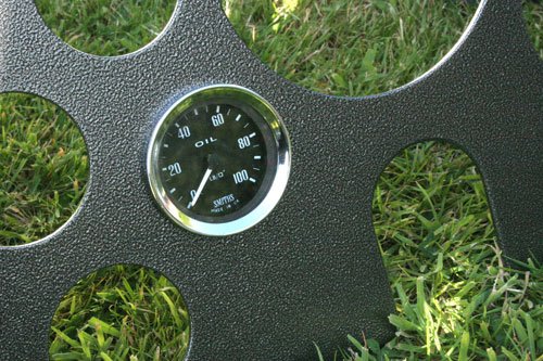
Dashboard in place with a couple of clocks fitted to see how it all looks, the surface has a slight texture that mimics stove enamel.

Now need to buy a few more clocks most likely off flea bay when a bargain appears.


Well that's it for now see you all soon.
4 Jun 2015, 5:19pm
Swifty - That all looks good. :cool:

Michiel has a similar surface on his dash on Spyder #47 & that looks the part too.

Good luck, Paul. :)
4 Jun 2015, 7:49pm
Cheers Paul i did get the original idea from Michiel's build.

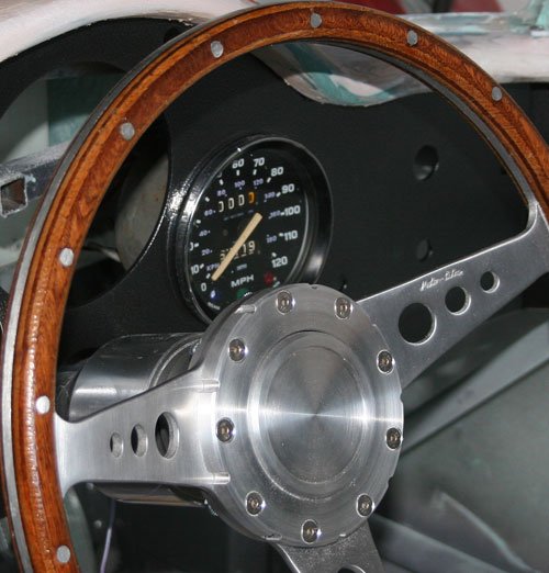
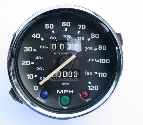
The speedo i bought off flea bay had a half black bezel so i've fitted a new chrome bezel with glass and seals.

A good guide on how to strip and repair speedo's can be found here in pdf format, written by Anthony Rhodes it covers the early to late speedo's, both Jaeger and Smiths.

IMG_5372.jpg
IMG_5377.jpg


The first image shows the original half black bezel and the second is the new bezel.


Well that's it for now see you all soon.
4 Jun 2015, 8:15pm
Love your gearbox tunnel Swifty!!
4 Jun 2015, 8:47pm
Scottie22 wrote:
Love your gearbox tunnel Swifty!!


Seconded. Isambard Kingdom Brunel would be happy with that. :)
6 Jun 2015, 9:10am
Cheers Guys, Mr T i now know where my inspiration came from, i just could not put my finger on it before. LOL


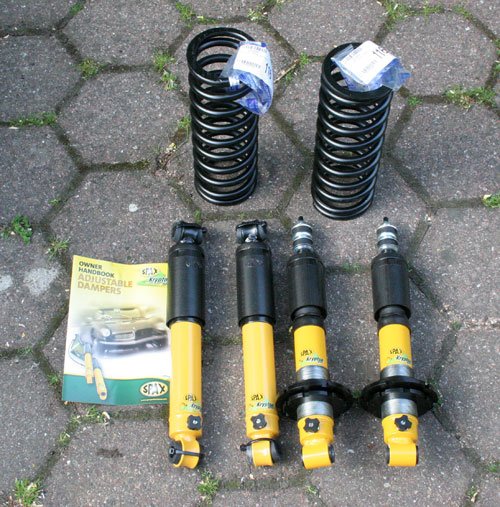
Some new goodies arrived which i hope to have fitted this weekend.

IMG_5375.jpg


After reading Mr T's post on suspension upgrade i decided to go ahead and change the suspension on my build which was the standard setup with tired old front springs and bog standard dampers and for some unknown reason the front offside was lying lower as the temperature has warmed up, the car has not moved so the settling in theory has not played its part plus we did have a cold snap for a couple of days and the front offside rose up to the original height.

By coincidence Rimmer Bros sent an email with 15% off all Spax suspension so after a little home work i've taken the plunge and gone for front ride/height adjustable with uprated springs of 200lbs and free length 280mm and rear ride adjustable. The rear also has a 1 inch lowering block fitted which i can machine if its too low.


Well that's it for now see you all soon.
6 Jun 2015, 9:33am
Hi there,

I have used a thermostat switch in an aftermarkt radiator used for GT6 engine (Vitesse MKII).

I used a dual switch. I beleive from a Peugeot 205 or something. Quite common. It's function is to trap the cooling from putting 1 fan to work or if circumstances ask for, 2 fans. You could either use the terminal for low temp engagement or swith the electric connection to the other terminal if you want the fan to kick in later.

Michiel
6 Jun 2015, 9:41am
Hi Swifty,

Can I ask where you got the new chrome bezels and glass from?

Andrew