MadaboutKitcars

This is a read-only archive of the old Madabout Kitcars forum. New posts and replies are no longer possible, but every thread is still here to browse and read.

Another Cordite Is Born ...

21 May 2013, 7:52pm
Mister Towed - Cheers, I'll happily leave the "rubber rings" off if that is what everyone else does.
As for being part of the driving experience in a Sammio, it sounds like it will be a 4 wheeled motorcycle.

As for the floor, I had already prepared some words covering that in the post below.
But basically the Cordite frame wraps around the chassis in the middle.
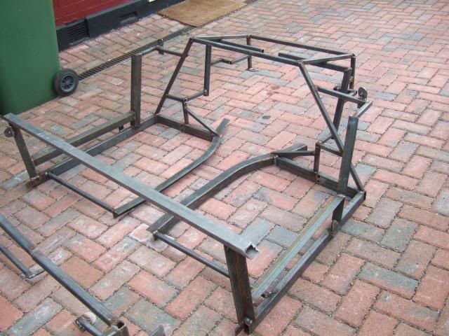


This appears to be different to the Spyder frame work & the new Navigator frame.

So the order of parts will be...
Chassis + Frame + Floor + Hand Brake Panel

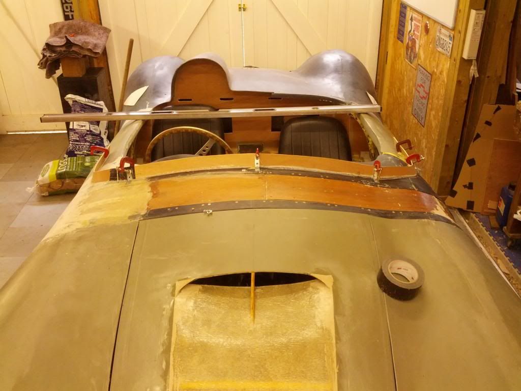
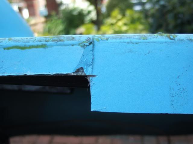
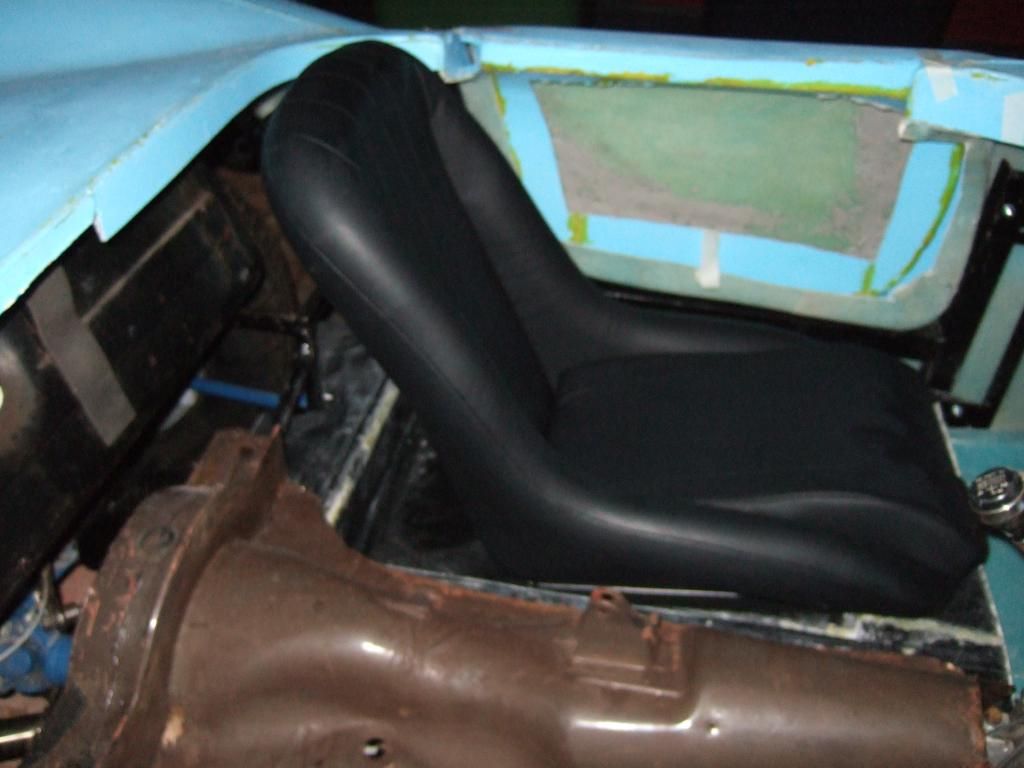
This is the best photo I have (and it is not great) with the fibre glass floor roughly in place...


- - - - - - - - - - - - - - - - - - - - - -

Tuesday:
Both my wife & I had tough days at work, so a family trip to the local curry house was in order.
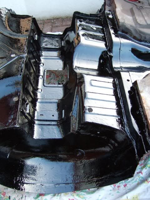
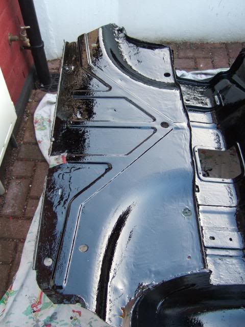
But as the sun was still shining when we go back, I got changed, pulled off the tarpaulin & got out the bitumen paint…

Spitfire Rear Wheel Arch Section:
I just needed to make sure I put a dust sheet underneath, as I've already got black paint on the driveway. :rolleyes:

Before:
( Although the Kurust dries black so it is not so easy to see. )
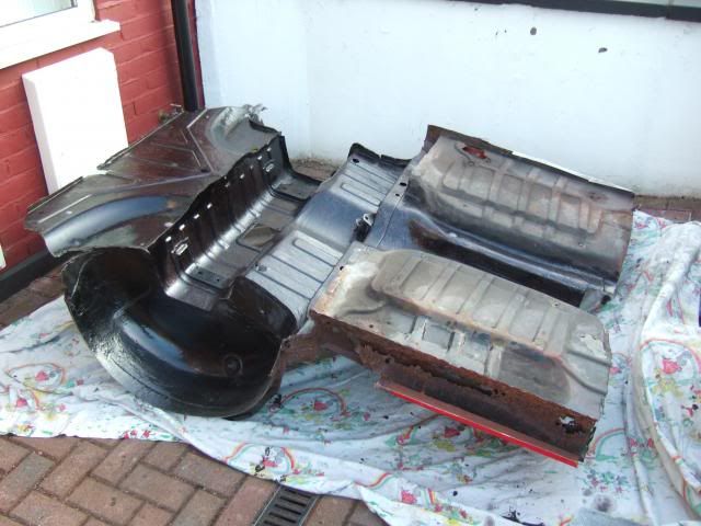


After:


I know it is just the first coat, but it still nice to see something heading in the right direction. :cool:

Although it will be dark by the time I get back out to put the tarpaulin back over the top.

Top Tip:
Whilst a good face mask keeps the paint fumes out, it also keeps the curry & beer fumes in. :rolleyes:

Rear Internal Framework - Planned Modification:
I have also been looking back at the work I did to make the separate hand brake panel fit over the frame.
The panel needed a lot of cutting before it would slot over the box section forming a cross bracing triangle.
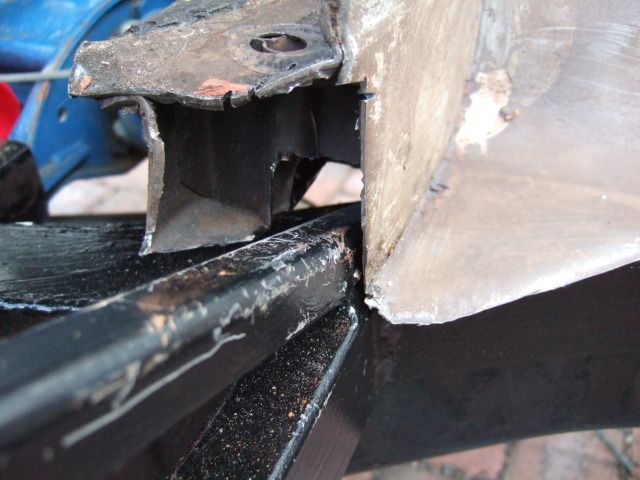
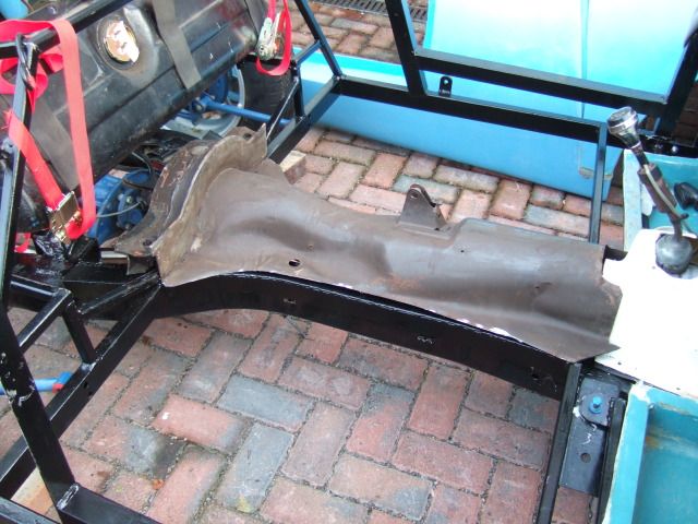


This time around I am going to cut that section of the frame out & weld in a new section at a different angle.

Which means it must be time for another one of my dodgy sketches…

( This represents a section of the frame on the passenger side, looking from the front of the car to the back. )


With this mod, the hand brake panel you see above would sit flush against the frame without any cutting.
So hopefully I should be able to keep this hand brake panel attached to the rear floor / arches section.

However, I still need to work out where exactly I can cut the rear section to keep as much intact as possible.

As this forms part of my "treading through" the frame issue:
- The mounting points at the back of the internal frame will need to sit on top of the rear arches section.
- Whereas the frame work will need to be underneath the hand brake section to sit on the chassis.
Although technically, it will need to sit on top of the lowered floor pans which will be sitting on the frame.

So as I was explaining to Mr T above, I need to co-ordinate the frame, floors & rear arches section.

I'll go though some more thoughts on the floors another day.

Cheers, Paul. :)
22 May 2013, 5:36am
Just a quick follow up to yesterday's post about the chassis/frame/floor/rear arches section...

Lowered Floor Pans:
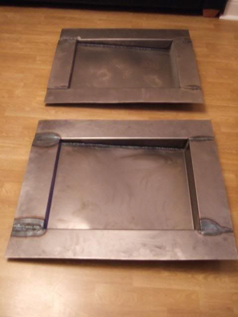
As previously mentioned, AndyP57 supplied me with a pair of these...


The good news is that these floors could actually be welded to the internal frame at the contact points.
This should add extra strength to the floor, before the body shell is then bonded / fibre glassed into place.

The only down side is the slope profile is the same as the fibre glass ones which was an issue for my seats.
The back of which have a fixed recline built in when they are sitting level, which the slope exaggerates.

Again, I previously posted this dodgy sketch of the issue a while back…


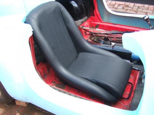
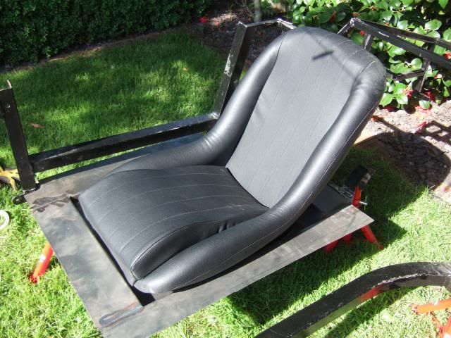
By comparison, I did test fit my seats in the original Spitfire floors as part of my "fast build" mock up…


Obviously the original Spitfire floor is lowered, but horizontal, which seems to be a big help.
So I will have another look at the new floor pans and where they fit within the chassis & frame work.
I'll then finally decide whether to alter the floors, or just bite the bullet & change the seats…

Alternative Seat Options:
Whilst it would be slightly annoying to replace the seats I have already have, it might be the easiest solution.

I have already spend some time looking at alternatives and they fall into two different "styles":
- Traditional classic car type seats with a low, but non reclined, back (similar to what I have now).
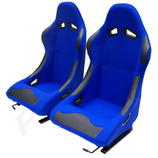
- Modern bucket seats with some head support & guide holes built in for a 4 point harness.

Not this particular version, but the same kind of thing...


Clearly the bucket seats would "stick out" higher than both the sides & back of the Cordite bodywork.
Which is why I think they may work as an "obvious" modern addition to my "1950s sports car".
Or they may look terrible & I will be shunned by the Sammio / Ribble community for being a heretic. :icon_wink:

Either way, lots to think about & its funny one decision can have a knock on impact on so many more.

Until next time, take care, Paul. :)
22 May 2013, 6:54am
Seats are something i have been thinking about lately as well Paul, i have a set of mini bucket seats circa 1970 but also have the original seats that came with my donor, im more of a mind to modify the donor seats for width etc so i can retain the adjustable rear rake.
22 May 2013, 7:30am
Paul, would you put your classic, low back bucket seats in a WRX Imprezza?

Or do you think that, perhaps, they just wouldn't look right somehow... :pray:
22 May 2013, 7:50am
Can't you just add shims to the back, or weld some blocks in place.
22 May 2013, 6:44pm
Wednesday:
Once again a cold dull day brightened up by the time I got home. :cool:
So I put a second coat of paint on the under side of the Spitfire rear arch section.
No photos as they would obviously look just the same as yesterday's photos! :icon_wink:

Viatron, Mr T & GaryH - Thanks for the replies chaps.
I know bucket seats would stick out like a sore thumb.
I also know that the floors could be adjusted to work.
But I already have a very long list of adjustments required.

AndyP57 was describing the new Navigator vs. the old Cordite the other day...

AndyP57 wrote:
... you should end up working with the kit and not fighting it...


So I guess this has become about picking my battles.
I really would like to reach the re-body inspection stage before the "summer" is gone.
Because, as I've said before, the winter months are not great for bonding & fibre glassing.

However, after what has seemed like forever, I am slowly fixing my build plan.

So until next time, take care, Paul. :)
23 May 2013, 6:36pm
Even though it sunny when I got home, I had to cut the grass & do some pruning.
I managed to take one photo (see below) & before I knew it, it was raining.
Still, makes a change to get wet trying to tidy up after gardening, instead of after working on the car. :rolleyes:

Seats vs. Lowered Floor Pans - More Thoughts:
Before I did anything rash in terms of buying bucket seats I thought I'd better double check the metal floors.
There was little room to spare in the fibre glass versions when I first test fitted a seat a few months ago…


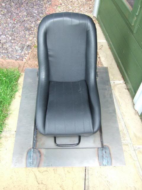
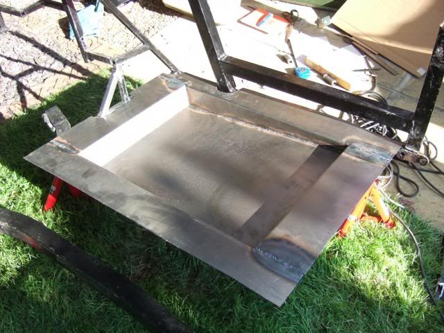
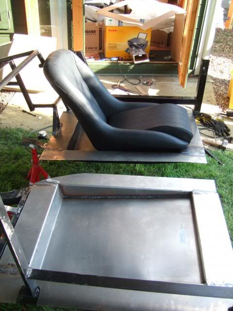
So I dragged one of the metal floor pans & a seat out of the summer house to try the same test again…


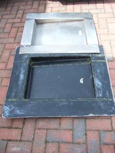
Thankfully, the 'cut out' width in the metal floors is the same size (just under 46cm) as the fibre glass one.

Which makes these seats on Ebay (which made me consider buckets in the first place) a tad too wide…


So my next step will be to have another look at the space available to fit the driver's side floor pan.
If I can get the lowered 'cut out' as close to both the front & inside as possible, my current seat might fit OK.
As based on test fitting the passenger side seat, the inside curve of the rear cockpit can get in the way a bit.
If I still need to steal an odd cm or two, I might remove the runners & bolt the seat directly to the floor itself.

Then, if all else fails, I will be left with a simple choice to either alter the floor, or change the seats.
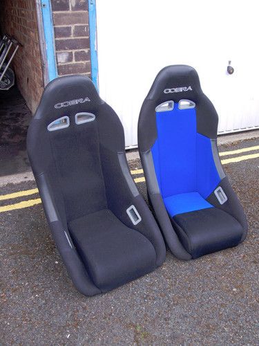
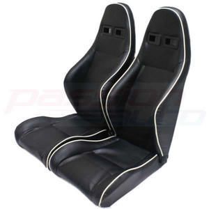
A bit more searching lead me to these seats which seem to be narrow enough to fit & look pretty good too…


I also realised there is yet another area I need to resolve as part of fitting the seats / floor…

Internal Frame vs. Rear Bodywork / Hump:
I've already mentioned the problem I have with the frame pressing against the body work / hump…


There is no simple fix, as both door cut outs in the body fit tight against the internal framework around them.
( So you can't move the body's position without removing the all the door frame work on both sides. )


Which means the Cordite body shell & internal frame work are effectively at an impasse. :icon_sad:

In addition, I was planning to attach a section of plywood in front of the frame to build a rear cockpit panel.
But this would actually create an even bigger gap between the rear bodywork lip & the inside of the cockpit.

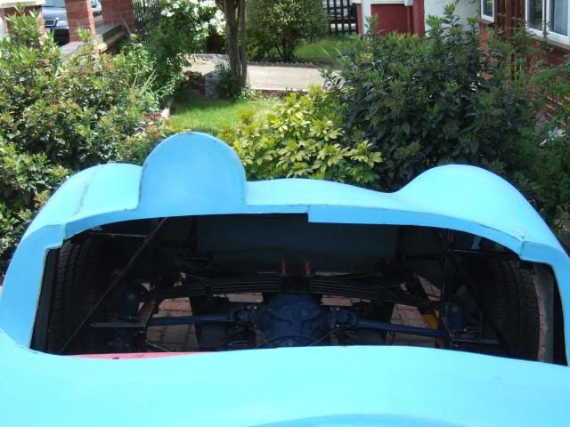
So I think I will have to cut off, extend & re-attach the body work at the rear of the cockpit, including the hump.
I know lots of Spyder builders have made similar cuts in their bodywork & rejoined everything successfully. :cool:

If you have been following the changes to the Navigator MkII mould, you will know there are alignment issues.
At this point, following my "pick your battles" approach to getting this car build, I will have some "wonky" bits.
I am certainly not going to attempt the wholesale changes required to make everything line up perfectly.

However, I did like the look of something CharmanTech has done under his hump on his G46…


If I have to remove the "face" of the hump anyway, then this would make it easier to fit plywood underneath.
I am also considering building the rear cockpit panel up by trimming & fitting plywood inside the internal framework.
I would then cover this "Mock Tudor" wall with fibreglass in the usual way to tie in the bodywork & the floor.

Other Odds & Ends
A couple of other things that will be related to the stuff above is the seat belt mounts & the 2nd hump.
I think the 3 point harness will be the most straight forward to fit as each seat just needs two mounting points.
( I will re-use the existing mounting points either side of the hand brake. )

I asked AndyP57 about the spare hump and he confirmed that all the humps made to fit the "driver's side".
Which means if I want to fit it, there will be a shed load of work to do, similar to CarNoob's approach.
So for now, I am going to concentrate on other priorities & come back to this at a later date.

With a bit of luck I will get some decent time on the car over the Bank Holiday weekend.

Cheers, Paul. :)
23 May 2013, 9:14pm
Paul if you wanted to cut the rear face off i have some sheet fibreglass i laid up going spare for the price of postage, it was laid up for our racer before we went carbon composite.
Check with Andy but im pretty sure that phase 2 of the navigator refresh will be moulds for sided humps which may help with your humping issues (fnar fnar), obviously with the rework means the passenger side hump wont be a perfect fit but it will surely fit better than trying to get a drivers side one to fit the passenger side?
.
25 May 2013, 9:58pm
Viatron - Thanks again for another kind offer Mac, but I have a lot of fibre glass stuff in the shed.
( Not that I have ever worked with any of this stuff before, but I will give it a go. )

- - - - - - - - - - - -

In the end, I only had a little time outside on the car today in the early evening....

I started by measuring & marking where I was going to move the bracing on the rear frame.
I also put some more thought into where the seat belt mounting plates would need to go.
I now have a plan for both behind the seat & to the side, but need the seat in place for a final check.

In the mean time I started cutting some the box section needed for the rear frame.

This is the new bracing angle and the cardboard templates I used to check the angles...


In keeping with the rest of the frame work, the two sides are not exactly the same. :icon_wink:

I've also started on some of the box sections I will need for the rear seat belt mounting plate...


( I'll try to put a quick sketch of the basic plan up tomorrow. )

I want to trim the metal floor pans to fit tomorrow, but this will need to be a two step process.
First I need to cut out the cross brace section that will be replaced with the angled sections above.
Then I can get the floors in place even though they will need a further trim around the new sections.
It is just that I want to see where the seats end up compared to the body before I remove the frame to start welding it.

Then I will remove the frame from the chassis & bring it into the rear garden for the welding.
( As I don't want to expose any people passing by to the welding arc light. )

Although as I moved the floor pan around today, I noticed, it needs some more welding.
As daylight was peaking through a selection of small holes in the existing welds...


Use of Heat Gun on Fibreglass Body:
At some point I will go around the Cordite body shell with an electric DIY paint stripping gun.
This follows a debate on Misted Towed's build thread about "voids".

Personally, I think my body has a few issues that hopefully Mr T will have avoided.

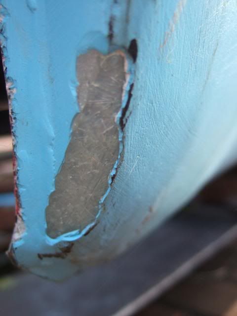
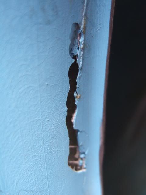
This is how one section of my body looked when it was delivered...


But the recent rounds of putting the body on and off have caused more damage...


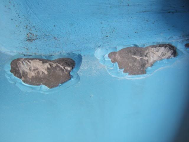
In both cases, it seems the gel coat has not bonded to the fibreglass behind it.
Especially in the photo above, as there is a big gap between the layers without using any heat.

But that is a problem for another day, as I need to get some sleep now.

Hopefully I've have a bigger update tomorrow, Paul. :)
26 May 2013, 10:20pm
Sunday - Part 1
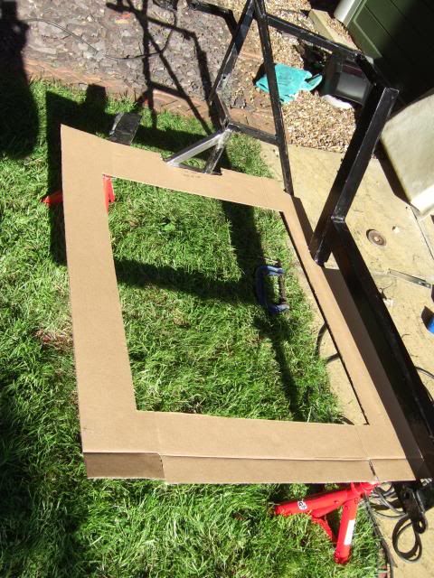
First job of the day was making a pair of cardboard templates for the metal floor pans...


As before, I used the "hole" from the middle to work out where they would fit.
I started on the driver's side, where I wanted the hole as far forward/inside as possible...


But when I went to check the distance to the rear frame work, I came up short...
( With the hole in this position, the back of the floor would be in mid air. )


The edges of the steel floors are not as deep as the original fibre glass ones...


Not quite the start to the day I was hoping for.
After several attempts at repositioning the "hole" it was clear I had a problem.
If the floor edges reached the frame, then the seat would never work.

At this point, I think I had a real break through in my approach.
Mister Towed often suggests I just do it and so I made my choice.
I know where I need the seat, so I will add an extra bracket to the frame work.
This will support the rear of the floor & I will fibre glass over the gap.
That was it, no more indecision, make a choice and move on. :cool:

Unfortunately, my optimism was sorely tested when I switched to the passenger side.
As I test fitted the cardboard template, it was clear that the back would reach the frame???

After a bit of head scratching & a long session with the tape measure the answer was clear.
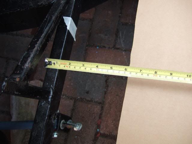
The passenger side frame work is not square & there is a 4 cm difference on one side.

This is the front frame rail on the driver's side (Spitfire bulk head still in place)...


And this is the passenger side and the gap to the bulk head is clear...


Decision made, cut this floor to fit the frame as it is & hope the seat will work.
But there was no point in finishing the template now as I was about to modify the frame.
So instead the body work came off & I unbolted the rear frame work.
With the frame put to one side, I packed everything away & relocated to the rear garden.
I had to get my wife's help to move the frame through the house to the patio.
I then took it to the back of the garden myself (no danger of hitting anything on the way).


Then it was the moment of truth, my first "real" welding job...

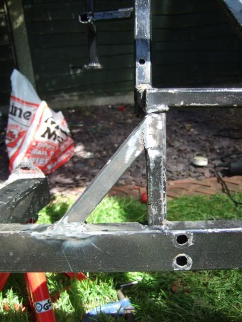
This was the cross brace on the passenger side that I was replacing.
( To allow the hand brake panel from the rear arches to sit better on the frame. )


I simply removed it with my angle grinder...


Then it was time to clamp the piece I had prepared earlier into place...


And this is the finished job after I have given the welds a bit of a clean up...


I did the "hit it with a big hammer" test and it is going no where.

Sad though it may seem, at this point, this was going through my head...

[Voice Over Man] Paul has welded some box section to his frame and now he is feeling EPIC! [/MoneySupermarket]

:icon_wink:

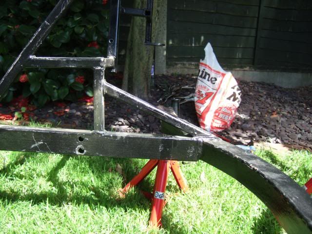
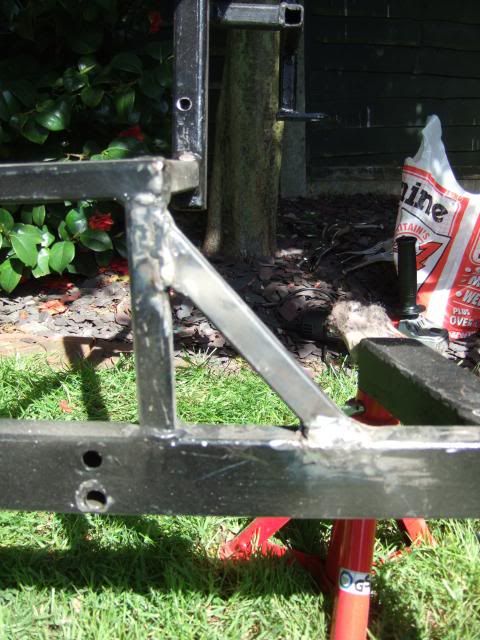
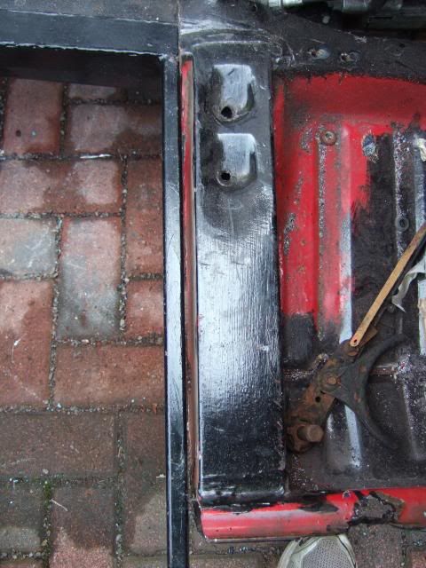
Next up was the driver's side, before...


During...


After...


At this point my daughters were desperate for me to put up the "Circus Tent" for them to play in.
Well it was a lovely day & I have turned the Summerhouse into a car parts warehouse.
So together we finally worked out the limited instructions and got the thing up...


I don't think my wife had imagined it was going to be as big as it is.
So I'm not sure it will be allowed on the front drive unless it is for a very short time.
( We will be packing it back up tomorrow as the rain is expected on Tuesday. )

That's it for Part 1, I'll be back with Part 2 in a minute.

Cheers, Paul. :)
26 May 2013, 10:28pm
Sunday - Part 2

Right, back with the build, next up fitting the driver's side floor pan.
I used my cardboard template to mark up the steel, before cutting it out with my jigsaw...


And then it simply slotted into place...


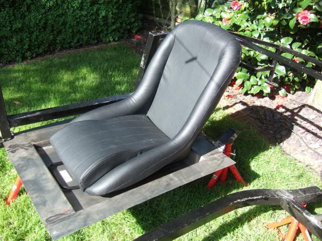
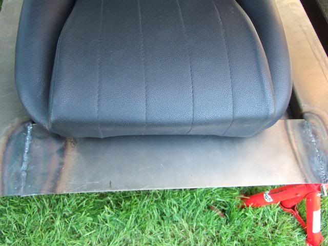
At which point I wanted to test fit the seat, just to see what I was up against...


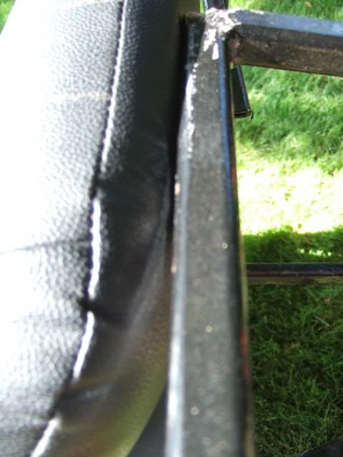
As expected, the rear of the seat hits the back of the frame...


Which in turn prevents the bottom of the seat runners from touching the floor...


The reality is that the seat runners will not work anyway, so I removed them...


For now, I've put the bolts back into the base just so I don't lose them...


Which means that the seats will actually sit lower than this when fitted.
The good news is that even at this higher level, they fit OK...


With a nice gap between the back of the seat & the frame...


All I needed to do now was cut a length of box section to fit and weld it in...


This should provide a bit of extra support to the floor (this also passed the hammer test).

Then I trimmed the cardboard template for the passenger side's floor to fit the new frame layout...


Quickly followed by trimming the steel floor to match.
The only problem I had was my jigsaw kept "spitting out" the blades.
So I used my angle grinder for the last bit of cutting required & test fitted it...


I knew fitted a seat on this side would be harder & in order for the back to fit like this...


Note:
I have trimmed the inside edge of the driver's floor to match the curve of the frame / chassis.
I will do the same thing to the passenger floor tomorrow.

The front of the seat will need to hang over the lip in the floor...


This means added a few spacers under the front mounting bolts.

I want to weld up the "holes" in both of the steel floors.

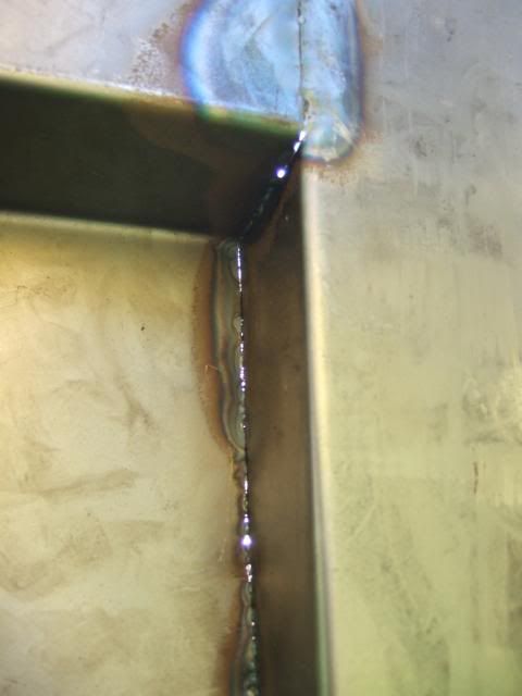
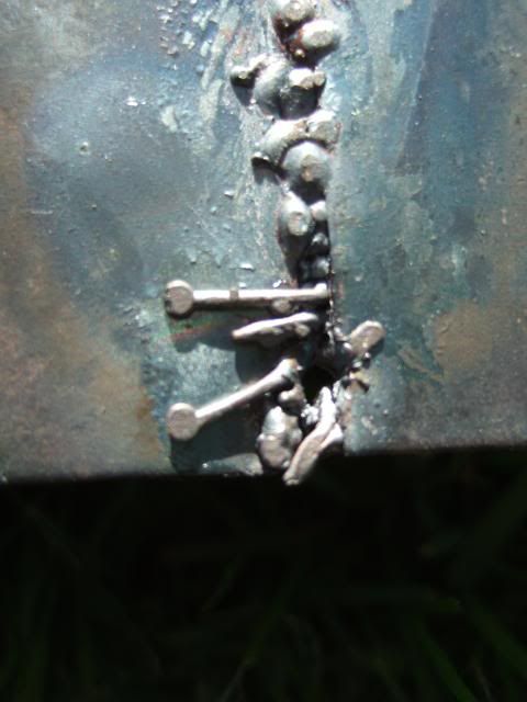
This is want the professional welding looks like in one area...


I decided to do some test welding on some of the floor off cuts first...


I didn't tidy up these welds, but I found a good setting to use & this is a solid join.

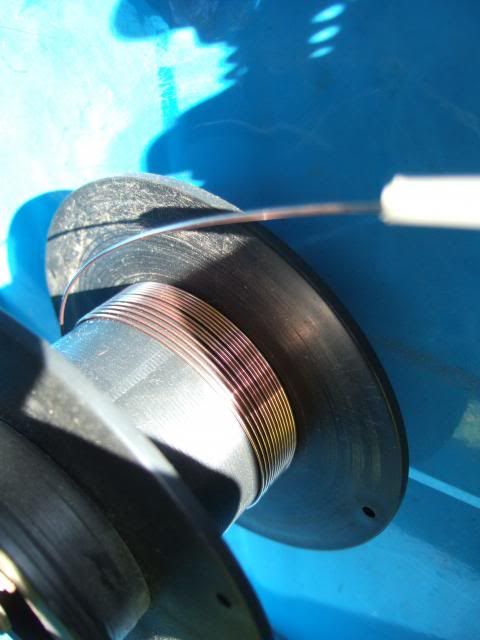
At which point I noticed I was coming to the end of my welding wire...


( I will go and get another reel first thing in the morning. )

As it had just gone 6pm, it was time to stop the angle grinder noises anyway.
It took me the best part of an hour to put everything away ready for tomorrow...


( If you look closely, you can see the frame tucked out of the way for the night. )

Then it was shower, time with the family & meal with my wife, before finally getting to type this up now.
So it has been a very long day, but a very productive one, so I am a happy boy.

Until next time, take care, Paul. :)
26 May 2013, 11:17pm
Nice work Paul, keep it up and your car will start coming together before you know it.

Welding isn't so hard after all, is it. :)
27 May 2013, 7:30am
Mister Towed - You have no idea how happy I was when my welding passed the hammer test.
Your "can do" approach to all the new skills you have learnt while building your car really helps me.

Ironically, the fact that the internal framework is "wonky" in places is actually encouraging me as well.
I can stop worrying about perfection, when "near enough" seems to have been the factory standard. :icon_wink:

Finally, I'm really glad that you are pressing on with your painting & I am looking forward to seeing it done.
It is clear to me that your body shell is definitely a much higher quality product compared to mine.
Which means that I will have to take a heat gun to it at some point (although I am not looking forward to that).

- - - - - - - - - - - - - - - - - - - - - -

Sunday Supplement:
There is one other thing I want to cover following yesterday's work...

I had seen this photo of the new Navigator MkII body shell under development on Viatron's thread...


I think the deep lip around the rear cockpit looks really good compared to the photos of mine I took yesterday...


This "step" was already cut into the rear cockpit lip when the kit was originally delivered...


So if I end up cutting this section out to fit the body work over the frame I will try to make the lip deeper all around.

- - - - - - - - - - - - - - - - - - - - - -

Right, I have a few domestic things to take care of before I can work on the car, so I'd better go.

Cheers, Paul. :)
27 May 2013, 7:53am
Paul, keep moving forward your perseverence is an inspiration to all im sure!

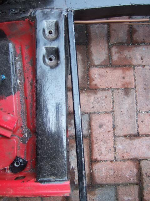
With reference to the frame being 4cm further back on one side i think this picture may give you a hint as to why


Im glad you like the lip, Andy and i discussed this and it serves two purposes, one it actually will help in the laminating process as having the lip lower means that the part of the mould that will fill the cockpit perimeter will be stronger and will therefore stop the moulds distorting and in addition the extra meat in the cockpit area makes the shells more stable for transport and gives builders more "meat" to play with, much easier to trim back than to add material. Wait till you see how deep the dash area is!

With reference to the "voids" in your shell dig them out and use bridging filler to fill them rather than normal filler as it will put strength back into the area, P40 is the well known brand but any fibreglass based bridging filler will do from your local body shop supplies place, make sure you clean the voids out first so there is no dust in them though as otherwise it wont bond, i usually blow them out with an airline then clean with a rag soaked in celly thinners or acetone if you have any.
HTH
Mac
27 May 2013, 8:56pm
Viatron - Hi Mac, this frame difference was at the front, causing a problem with the floor.
Although the fix you have done at the back covers the issues I had with the wheel arches not lining up.
As I said to Mr T I am not looking forward to checking for voids, but my shell really needs it.
All tips and advice are always welcome. :cool:

- - - - - - - - - - - - - - - - - - - - - -

Bank Holiday Monday:
First job of the day was a trip to Machine Mart to pick up some welding wire.
Was reminded of a Phil & Barry's run out as I passed two classic racers in convoy.
Not sure what they were, but both looked something like this...


I then passed a Bugatti Veyron Convertible going the other way on the way home.
Must be something about the sunshine that brings everyone out.

Anyway, back to my build & I started by welding up the holes in the passenger side floor.
It was really windy outside which wasn't helping, but I did get it all sealed up.
( Not that you will be able to see much of a difference in this photo. :rolleyes: )


I started working on the floor as I didn't want to start the angle grinder up before mid-day.
I then got the rear frame back out so I could work out where to put the rear seat belt mounting.
I am going to use my 3 point harness & want it to start behind the seat around here...


Initially I was going to run box section across the whole length of the cockpit.
Thankfully I remembered that the petrol tank needs space to be fitted.
So I decided to build a 90 degree frame that would extend from on top of an existing frame rail.


So it was time to set up a workshop picnic area to start cutting the box section to length...


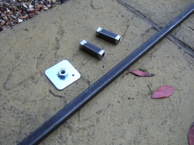
This is what I ended up with, although the edges will be angled to match the frame when welded in...


Obviously I needed a matching set of box section for the passenger side too...


My wife took our girls to visit her sister, so I was able to set up another picnic inside the circus tent...
As by now it was just too windy to weld outside & the tent felt like it wanted to take off too.


If my bracket doesn't end up square, it will not be for want of trying...


Once the first two pieces were joined, I had to clamp everything together to get the 3rd piece in position...


Once the first joint was welded I could remove everything else & finish off all the sides...


Then it was time to clamp everything up for the final time...


With the seat belt mounting plate in the middle of the box section, I could weld on both sides.
But, unfortunately, my mate's welder decided to cut out at this point as it got too hot.

So I returned inside to do some hoovering (I kid you not) as I can't spend all day playing with my car!

Eventually I got back out & managed to finish one section completely...


I had been matching the other side section by section, so that is nearly done too.
( The welder packed up again as it was actually pretty hot inside the tent despite the wind outside. )


I will be the first to admit that my solution may have a hint of over engineering about it.
But I am pretty happy that this be good and solid when finally welded to the frame.

It only took me 45 minutes to back up this evening, so I'm getting quicker.

The frame is now tucked away & under a cover given the weather forecast of rain...


I then had to spend some time pruning in the garden before the family returned.
Then my girls helped me take down the circus tent, which they really love.
Unlike my wife who has now insisted that this is never put up on the front drive.

Anyway, another good day's work, still a bit to do on these brackets, but getting there.

Quick Quiz - Just for fun:
What is the difference between this photo of my bracket which has cooled down...


And this photo of my bracket that was still very hot to the touch after welding...


Obviously the answer is there is no difference, which is why I picked it up with my bare hands!!

I was actually using the angle grinder outside the tent to dress the welds.
As I figured sparks inside the tent was not such a good idea.
So I kept changing gloves from my welding ones to my normal working ones.
Either way, my mind was clearly not thinking straight when I grabbed it.

Until next time, take care, Paul. :)
29 May 2013, 6:57pm
More Welding:
Despite the rubbish weather I wanted to finish off the welding on my seat belt mounting brackets.
I can't weld the brackets onto the frame itself until the weather improves, as I need a big area to play in.
But for this job I just needed a patch of dry ground & I was away…


Thankfully I had almost finished on Monday evening when the welder cut out, so it didn't take me long...


Although I still have to dress these new welds as it was too late to start angle grinding.
Then I used the cardboard underneath to trace round & cut out the shapes of these brackets…


I will then offer up these templates to the rear frame work to mark the angles where the brackets will join.
Then I can simply mark & cut the ends of the brackets so that they will form neat joints to be welded in. :cool:

Frame to Chassis Holes:
One thing I forgot to do before I removed the rear frame from the chassis was mark up the seat belt holes.
These sit either side of the hand brake panel, and I'd previously made cardboard templates to locate them.
Unfortunately, I now can't mark/drill these holes in the frame without dragging it back through the house.
The knock on effect is that I can't mark up & drill the corresponding matching holes in the floor pans either.

As previously mentioned, I will be building a Scooby Doo type sandwich of parts:
- Chassis
- Frame
- Floor
- Hand brake panel

So I will add that to the list of jobs I need to do when I attempt to "dry fit" all of the above parts together.
This test fitting will determine if the idea of welding some of these items together will work in practise.

I also need to drill 4 extra holes in the internal frame so that it can be bolted to the chassis front & back.
That way the seat belt holes will predominately be for the eyelets, rather than keeping the frame in place.

I know DonnySoutherner simply drilled straight through the Spitfire chassis & bolted his frame in that way.
I plan to do the same thing, but will cut out some square sections of the thick sheet steel my mate gave me.
If these squares cover the width of the chassis rail underneath, I hope this will spread the load sufficiently.

Which leads me to my final thought of the day…

Frame to Chassis Bolts:
I can measure the length of the bolts required to go through the frame and chassis.
But does anyone have a suggestion for the minimum size/type of bolt I should use?
Instinctively, I would have thought at least M10 size, but I'll happily order whatever size I need.

Next Steps...
I might take advantage of the rain to have another sort out of the pile of boxes in the Summerhouse.
As I can’t find one of the seat belt mounting plates that I need to fit to the side of the frame work. :rolleyes:

I bought 4 plates (2 big ones & 2 smaller ones) and used one of each to work out possible location points.
Thankfully I found the 2nd big plate which was needed to the brackets I was welding up at the weekend.
But the 2nd smaller plate had gone AWOL & welding that into place will be the next big job on the rear frame.

Until next time, take care, Paul. :)

PS
With a bit of luck I will be able to reply to some of the other build threads this week.
29 May 2013, 8:00pm
Paul,
M10 will be alright but i would worry more about the grade of bolt, try and get eitther 8.8 or 10.9's. if you are drilling right through the chassis box consider sleeving the hole with some tube as bolting straight through box usually ends up with the box deforming and the bolts working loose over time.
Mac
30 May 2013, 6:33pm
Viatron - Thanks for the bolt recommendations Mac, I'll order some, along with a few other bits I need.
I have seen the "tube inside the chassis" modification done on other car builds so I know what you mean.
But can I just check whether my "steel square" idea would do a similar job (as it would be much easier for me).

This is a photo of DonnySoutherner's frame bolted into position…


Obviously the "angle iron" inner section of the frame work would spread the load across the top of the chassis.
And here is another one of my dodgy PowerPoint sketches to show my plan for underneath the chassis…


The steel is approx. 2 mm thick and I would cut it to cover the full width of the chassis underneath.
I figured this approach would spread the load evenly through the vertical sides of the chassis.
Whereas, just using a nut & washer would clearly load the centre of the horizontal face of the chassis.

However, I am happy to go with your superior knowledge & add you to the list of people who I owe a beer!

- - - - - - - - - - - - - - - - - - - -

Seat Belt Mounting Brackets:
I had a very quick session with the angle grinder after I got home from work to tidy up my welding...


Thankfully, the day's wet weather meant the washing line was free to become part of my alfresco spray booth. :rolleyes:


But a light dusting of "weldable" etch primer later and everything looks a lot better…


Two other things occurred to me in relation to these brackets:
- I need a length of box section running "front to back" to resist the pull of the belts under braking.
- I really need to double check I can get the petrol tank in before I weld everything in place!

That's all for now, cheers, Paul. :)
30 May 2013, 6:55pm
Paul the advantage of a crush tube is that you caan just drill the right sized hole for the tube to go into, i guess a piece of box might be ok but i would fancy trying to cut an accurate square hole in my chassis!. My plan is to drill a hole straight through from top to bottom (already done) to the size of bolt then re drill the top hole to the size of the tube, that way i can just drop the tube in from the top, suitably trimmed so its fractionally below the level of the top of the chassis. Once you then drop the bolt in and tighten it up it will pull the top in fractionally to the level of the top of the crush tube but then stop. you could weld the tube in at the top but i dont think it will be necessary. hope that makes sense as now i re read it it seems a bit of a ramble!!!!
30 May 2013, 8:10pm
Cheers Mac, that makes sense, but I probably wasn't very clear myself. :rolleyes:

The "steel square" is effectively an extra "chassis shaped" washer if that makes sense.

So no cutting & welding to the chassis at all, just a hole drilled straight through for the bolt.

Is that a better explanation?

Cheers, Paul. :)
30 May 2013, 9:18pm
Yep but the hole in the top is bigger than the one in the bottom to allow the crush tube to drop in
30 May 2013, 9:32pm
OK, we are definitely talking at crossed purposes now.

I understand your point about the crush tube & how it gets fitted.

I was trying to clear up my sketch above, which should have shown the 'green' square sitting on top of the 'purple' chassis.

It was not my intention to cut a square out of the chassis and weld the green square into position.

I just thought the steel square would act as an over sized "washer" to spread the load and avoid any crushing.

Is that any clearer?

Cheers, Paul. :)
30 May 2013, 10:02pm
Sorry yes clear now, having a spreader blate on the bottom certainly wont do any harm at all, we got there in the end!