This is a read-only archive of the old Madabout Kitcars forum. New posts and replies are no longer possible, but every thread is still here to browse and read.
Brakes bled... (I had to really - I let air get in the lines when I re-did the feed pipes to the MC)
...And back from a shake down blast.
IMHO, It's better than the initial dual servo we tried. I took her up to some miles an hour, stood on the brakes (no one else was around) and she locked up, fronts first. I know this from the tyre smoke that came from the front.
Did it again with less hooliganism, and the pedal feel is spot on. You can easily gauge how much force to put in, and emergency stops are quick and can be down with out locking up. Who needs ABS?
Pootling round town and at speed on the dual carriageway it feels great. A top upgrade!!
May be I have missed a point or I am incredibly thick but the servo looks to have been designed for the m/c to bolt directly onto it hence the two fixing studs. Now for those of you with the reservoir mounted on top of the m/c this creates a problem because the holes need to be further round so that the reservoir sits with its filler cap on top, therefore Mike has been innovative in designing and having made the new 6mm plate which now has offset studs to mount the m/c and at the time nobody new it was a sealed unit. This creates a small problem in that Jasons small extension has to be made to marry up the two operating faces between the servo and the m/c.
But...............for those of us who have remote reservoirs, if this new plate was not fitted and the m/c was fitted direct to the servo the new plate would not be needed and the servo and m/c faces should marry up ( more or less )
Are you still with me or is this gobbledygook ?
In a perfect world, you'd be right Dennis - but the problem is that neither the Ford or the BMW master cylinder have the correct size fixing holes, or have those holes on the same PCD as the studs on the servo. Hence the need for the adaptor plate.
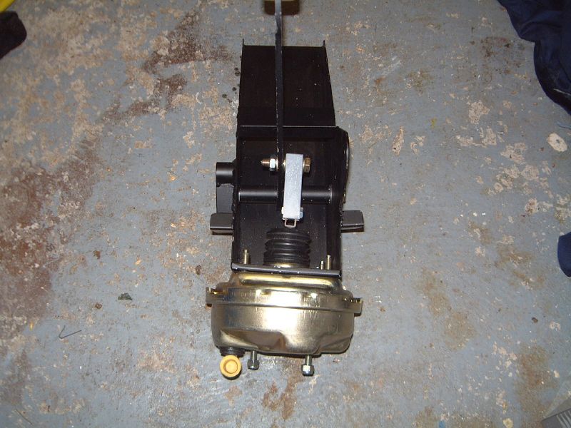
Just started to strip the old Metro servo out and found that under some silicone sealant there is a pack of washers on the servo securing studs on both top and bottom outer locations between the servo body and the pedal box. This cocks the servo inwards which may help bonnet clearance but not sure what it does for the alignment of the servo-to-pedal pushrod. Has anyone else "retro fitting" the dual unit seen this on their existing installation? Pics attached.
I am hoping that if I fettle the holes in the pedal box with an inwards bias this packing may be redundant and I may be able to get the new clevis either side of the brake pedal. Peter.
Forgot to mention that on my master cylinder as well as the raised cast number "22" there is also a raised cast "Ford" logo. So did Ford make their own master cylinders or just get Girling to put their name on them???
Just started to strip the old Metro servo out and found that under some silicone sealant there is a pack of washers on the servo securing studs on both top and bottom outer locations between the servo body and the pedal box. This cocks the servo inwards which may help bonnet clearance but not sure what it does for the alignment of the servo-to-pedal pushrod. Has anyone else "retro fitting" the dual unit seen this on their existing installation? Pics attached.
I am hoping that if I fettle the holes in the pedal box with an inwards bias this packing may be redundant and I may be able to get the new clevis either side of the brake pedal. Peter.
I guess your are correct and that this was to get the clevis to line up with the brake pedal. I modified the bush of my brake pedal to offset it to make this easier. (See pics earlier in this thread). A much better solution and not tricky to do.,
Just started to strip the old Metro servo out and found that under some silicone sealant there is a pack of washers on the servo securing studs on both top and bottom outer locations between the servo body and the pedal box. This cocks the servo inwards which may help bonnet clearance but not sure what it does for the alignment of the servo-to-pedal pushrod. Has anyone else "retro fitting" the dual unit seen this on their existing installation? Pics attached.
I am hoping that if I fettle the holes in the pedal box with an inwards bias this packing may be redundant and I may be able to get the new clevis either side of the brake pedal. Peter.
The Sportster pedal box in my car was made at an angle and the clevis is deliberately offset. Like this....
(obviously this was with the metro servo during my build and the pedal box is upside down )
I suspect Mike's Cabrio is the same but maybe earlier Cabrio's had the packing washers like yours.
I suspect you will need to re-use them in the same way.
Just started to strip the old Metro servo out and found that under some silicone sealant there is a pack of washers on the servo securing studs on both top and bottom outer locations between the servo body and the pedal box. This cocks the servo inwards which may help bonnet clearance but not sure what it does for the alignment of the servo-to-pedal pushrod. Has anyone else "retro fitting" the dual unit seen this on their existing installation? Pics attached.
I am hoping that if I fettle the holes in the pedal box with an inwards bias this packing may be redundant and I may be able to get the new clevis either side of the brake pedal. Peter.
Peter
You raise a number of separate issues:
1. the washers will have angled the servo in toward the engine. There is no problem with this as it is the nuts on the servo which pull against the firewall that take all the pressure under braking. The waskers simply act as spacers in the non use state.
2. Are the washers needed? I cut a section out of my side panel to make room for the Metro servo, only to find when I had everything in its right place, a cut out was not necessary. I plan to weld the missing piece back in again.If the panel rattles against the servo I will glue a small piece of neoprene rubber belt to the servo to prevent noise/rattle.
3. If your servo clasp will not line up with the pedal, I would suggest twisting the pedal stem until it alignswith the clasp. A pair of mole grips will be sufficient.I know I keep going on about this but the original Marlin design was crap with the pushrod offset. A clasp either side of the pedal is so much better.
4. The hole centres on the Metro are 90mm: the new servo has 85mm centres. If you fettle all the 5mm from the top set of holes downwards, and from the outer holes toward the centre, you will improve clearances both under the bonnet and from the side panels.
The Sportster pedal box in my car was made at an angle and the clevis is deliberately offset.
I suspect Mike's Cabrio is the same but maybe earlier Cabrio's had the packing washers like yours.
I suspect you will need to re-use them in the same way.
V* Peter
Peterux is correct with his assumption. My pedal box is just like his.
If you look down on yoursfrom the top can you see the difference in angle between the servo interface, and the firewall interface? If not then I agree with Peter, you will need your packers again to achieve the same effect.
Mike
Yes I think I have the older version pedal box (Pics attached). I used to think my pedal box was angled but now you can see that it's the packing washers under the silicone seal that are doing the offset.
You can also see that the crude cut out in the side panel is not even in the right place as it still fouls the Metro servo! I will bias the dual servo mounting holes as suggested, then see what is happening at the clevis end, then add washers as required and see what clearance I get under the bonnet. A voyage of discovery eh! Peter.
Yes I think I have the older version pedal box (Pics attached). I used to think my pedal box was angled but now you can see that it's the packing washers under the silicone seal that are doing the offset.
You can also see that the crude cut out in the side panel is not even in the right place as it still fouls the Metro servo! I will bias the dual servo mounting holes as suggested, then see what is happening at the clevis end, then add washers as required and see what clearance I get under the bonnet. A voyage of discovery eh! Peter.
Peter
With the new adaptor plate, you will be able to roll the master cylinder around to near vertical, which will help bring all your pipework more in board.
I really do not think it matters putting spacers in to toe the servo in towards the engine. Its what holds the studs in to the pedal box that really matters: fit the biggest washers you can behind the firewall and it will be fine. Plus an infill of silicone and it will look like the later models again.
Mike
May be I have missed a point or I am incredibly thick but the servo looks to have been designed for the m/c to bolt directly onto it hence the two fixing studs. Now for those of you with the reservoir mounted on top of the m/c this creates a problem because the holes need to be further round so that the reservoir sits with its filler cap on top, therefore Mike has been innovative in designing and having made the new 6mm plate which now has offset studs to mount the m/c and at the time nobody new it was a sealed unit. This creates a small problem in that Jasons small extension has to be made to marry up the two operating faces between the servo and the m/c.
But...............for those of us who have remote reservoirs, if this new plate was not fitted and the m/c was fitted direct to the servo the new plate would not be needed and the servo and m/c faces should marry up ( more or less )
Are you still with me or is this gobbledygook ?
Hi Dennis
The new servo is American, and designed for great big master cylinders with great big flanges, with great big holes and a great big diameter. The fixings are also set either North-South, or East-West.
The European Ford and BMW car master cylinders are both much smaller. The flanges are not big enough to fit directly on to the new servo fixing posts, and do not align North - South, or East-West, but 22 degrees offset - hence the need for the adaptor plate - to allow the fixing posts to be brought in to a smaller diameter, rotated 22 degrees, and reduced in size (from 10mm to 8mm)
All will become obvious when you offer a car master cylinder up to your new servo. Pictures alone are sometimes misleading.
Unless you have a master cylinder with a great big flange and great big holes and .............?
Having built the car without cutting out inspection openings int the bulkhead,removal of the metro servo was done by turning myself into a contortionist to get into the footwell backward ,upside down and back-to-front.My resolve was strong(but painful-can hardly walk today) and it is out.Can I ask...those who have fitted the new clevis,did you leave the bolt on the input shaft and screw the clevis up to it tightly to get the desired length...in my case 13 cm from mating face of servo to centre hole of clevis.
Jeremy - I'm also a fully paid up member of the MCS (Marlin Contortionist Society)
That's how I put my old metro servo in, and out, and the test servo in (and out) and finally the permanent chrome servo. Call for the osteopath!
As for the clevis on the input rod, I left the nut on there and used it to lock against the clevis once it was adjusted correctly. There's not much chance of the clevis unscrewing once it's either side of the pedal, but I reasoned that its an extra set of threads to exert the pressure against.
Jeremy - I'm also a fully paid up member of the MCS (Marlin Contortionist Society)
That's how I put my old metro servo in, and out, and the test servo in (and out) and finally the permanent chrome servo. Call for the osteopath!
As for the clevis on the input rod, I left the nut on there and used it to lock against the clevis once it was adjusted correctly. There's not much chance of the clevis unscrewing once it's either side of the pedal, but I reasoned that its an extra set of threads to exert the pressure against.
Jason
I wondered if it was necessary to fit the lock nut. I concluded that whilst the clevis can not rotate to undo itself, the servo push rod could theoretically rotate through vibration, unless it is locked off.
So I think the lock nut should be fitted.
As for being a paid up MCS member, you guys are 10 years younger than me!
It would have made a good photo of any of us I suspect - head first in the footwell with feet sticking up out of the top of the seat, muttering expletives eep: - why do we do it?
Mike
Having built the car without cutting out inspection openings int the bulkhead,removal of the metro servo was done by turning myself into a contortionist to get into the footwell backward ,upside down and back-to-front.My resolve was strong(but painful-can hardly walk today) and it is out.Can I ask...those who have fitted the new clevis,did you leave the bolt on the input shaft and screw the clevis up to it tightly to get the desired length...in my case 13 cm from mating face of servo to centre hole of clevis.
Sorry Jeremy - didn't answer your question!
I measured the firewall to clevis hole centre distance on the Metro servo set up, and replicated that for my new servo by screwing the clevis on outside the car. I locked the clevis off with the nut, and fitted it. I had to sligtly twist the pedal to make it align with the clevis. But that was the easy bit.
I decide to change my pedal box/firewall bolts and add a larger stainless washer. Removing the nuts inside the footwell to get them out was difficult. Putting the nuts back on was almost impossible! I even had Sue contorting with me inside the footwell.
Now that photo would have been embarrassing!
Having loaded up with pain relief, and done my warm up exercises ,I am ready for the return journey.Main consensus seems to be to try place the clevis either side of the pedal...did you bot this thru, or use the clevis pin supplied?
Clevis pin as supplied, with a split pin through the hole at the end to stop it from coming out.
I used my old clevis pin, as it had a recess for a circlip. A bolt with a nyloc nut to allow you not to over tighten, and stop it coming undone, would be fine.
Do you know a good chiropractor?
(- am I right thinking you are a doctor, or did I dream that one up?)
Mike
Yep mike that's rite...adds a new meaning to "Physician heal thyself". With regard to the pedal box, I welded the nuts in the firewall on the inside, so removing the bolts and box would be done from the engine side.
re the pedal box, I have drilled for bolts but why would rivnuts not be adequate? Also, should it be secured from above too? It seems like it should to me...John
I think securing the pedal box from above would be a good idea. The locations on the "front" face of the box look well suited to rivnuts to me which would make things a lot easier. I have been reluctant to add strengthening as yet because I am really early in the build and I want to be sure that I won't impede anything else that might need fitting in the future. I will look through the forum for more direction.
Also, my newly cut access hatch will help if I decide on bolts not rivnuts. I have to confess to a bit of a fixation on rivnuts...!



 eep:
eep: 

 - why do we do it?