This is a read-only archive of the old Madabout Kitcars forum. New posts and replies are no longer possible, but every thread is still here to browse and read.
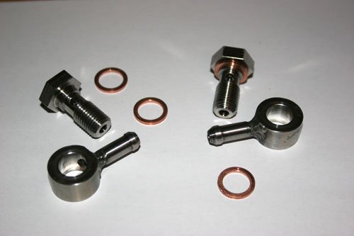
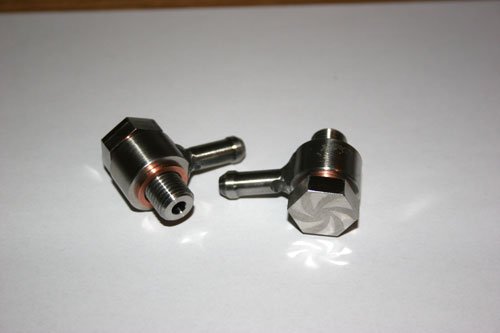
Finished off the two stainless steel banjo fittings with 7/16 unf thread to suit the master cylinders and four copper washers. The pipe tails were tig welded.
Ive tried them in place and they will work so i need to finish the bulkhead fabrication then mount master cylinders and reservoirs to bleed both the brakes and clutch.
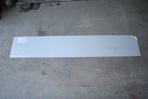
Today i spoke to a local plastics company who have the facility to profile the screen from makrolon but i think as i am not 100% sure of the final shape i'll buy an uncut sheet and work from there, one advantage of profiling is the neat polished edge but i am sure i will be able to polish the edge once i have the shape I'm happy with.
I originally had a gauze filter fitted to the rocker box vent but after reading various posts about oily smells i decided to fit an oil catch tank which will be piped between the rocker box and inlet manifold.
Looked around to buy one then decided to make a one off special tank out of ally.
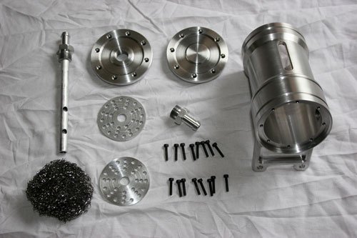
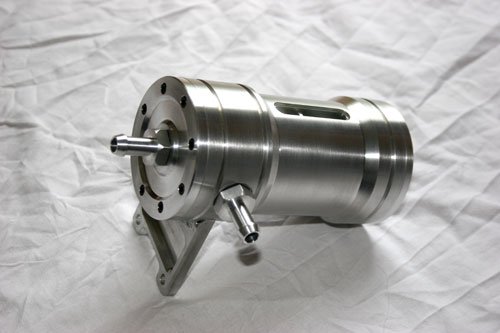
Its made from a main body bored out with various tapped holes and a machined slot fitted with a glass view window to check the oil level for future maintenance.
Both lids have eight holes on a pcd matching the holes in the body, the lid has a center hole tapped out to 7/16 unf for the tube tail to screw into and the bottom cover will have a center hole tapped to match a drain tap or plug once i find a suitable part.
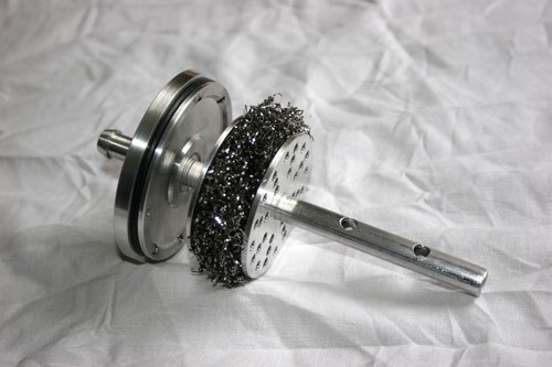
This part is the lid with the separation tube and steel gauze fitted between two drilled ally discs, the open ended tube sits about 10mm off the bottom cover with two 5mm dia through holes.
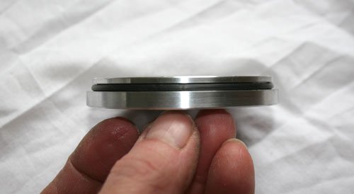
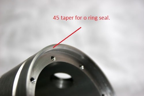
Both the top and bottom covers are sealed by an o ring which sits in a groove, the o ring then clamps down onto a 45 degree taper as shown in the second photo.
Oil catch tank assembled with 8mm pipe tails and mounting bracket tig welded to the body.
Thurcroft flyer, garyh and Paul Thanks for the comments.
A question about piping in an ally rad with a header tank.
Am i correct in thinking the return to the header tank (top pipe) comes from the thermostat top cover outlet and the header tank outlet (bottom pipe) is piped into the steel pipe that runs under the carburetors returning back to the water pump.
I have read that the flow into the header tank may be to high so a re-stricter is fitted to the return to slow the flow down otherwise the cooling system will not run efficiently, has anybody come across this.
Found a good reference vid on you tube from a guy who has fitted a header tank to a GT6 engine, here's the link http://youtu.be/BIVKnDXY1Dg My original thought about how to pipe the header in was correct, now need to figure out what pipes and bends are required.
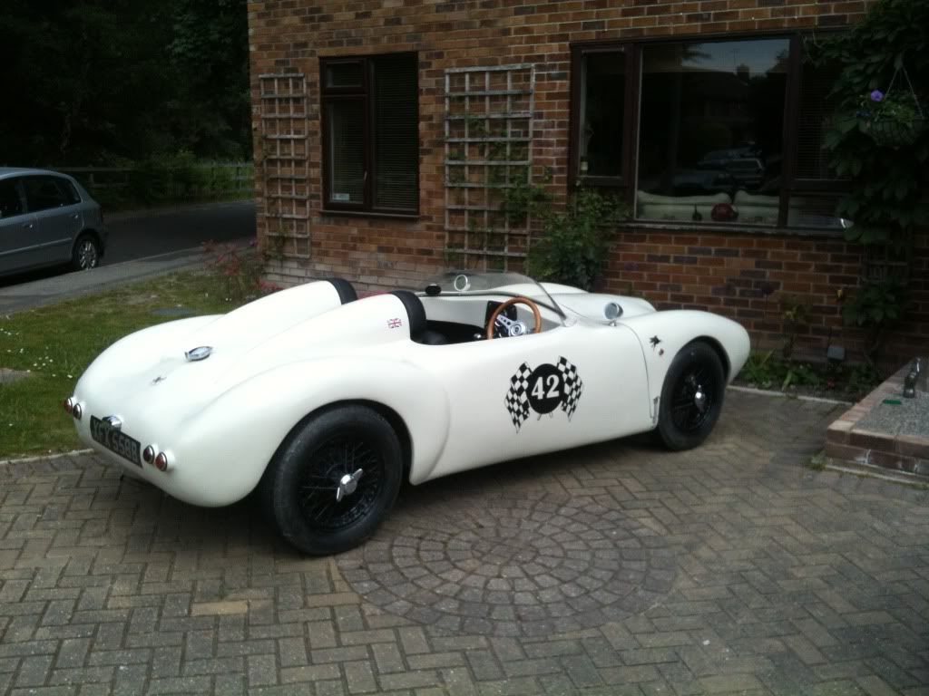
Today there was some good news in the post the V5C was delivered, they have changed the make to Triumph Spyder so all is well, now just need to crack on and get it on the road.
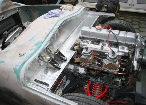
Ive finally finished paneling the bulkhead exterior in ally sheet, it seems to of taken for ever, a lot longer than i anticipated but at least that is one more job off the list. The next paneling is the interior then the dash so onwards and upwards.
Looking at lot neater than the standard fiberglass plus i now have something solid to mount the accessories on to.
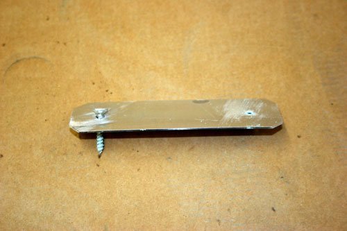
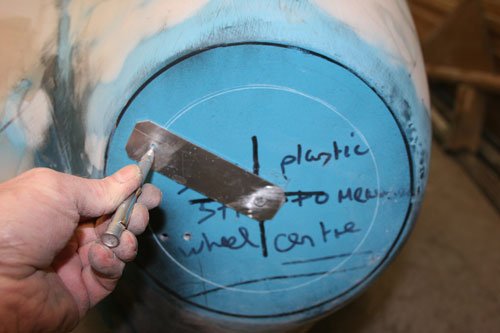
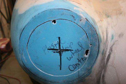
Next job was to mark the hole for the front headlights, made a simple tool to scribe the required diameter, its a piece of 1mm ally with two holes matching the radius.
Tool screwed to the circle center with scribe to mark the circumference.
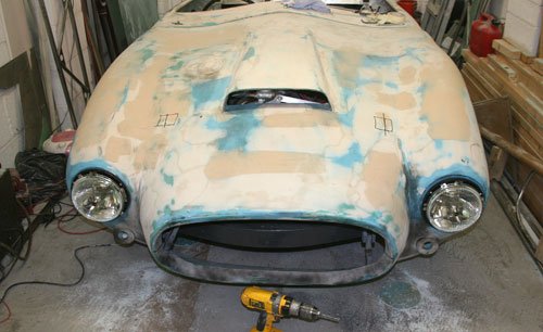
The filler looks worse in the photo than it is in real life. I am after a smooth flowing body so have filled every little imperfection that i find this i have followed through the whole body but keeping the filler as thin as possible, the bonnet has however had a lot of work to try and align the mess that the standard bonnet came with so hopefully once painted it looks ok.
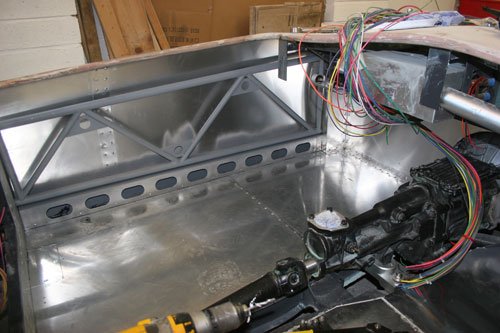
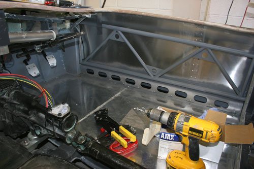
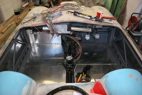
Cracked on this weekend with the interior paneling to tick it off the list. Used the new pop rivet hand gun i bought which has a swivel head and can say that it's a god send for difficult to reach panels especially corner joins, its the one with yellow handles in the picture below, if anybody wants a better picture of it let me know and ill post a couple.
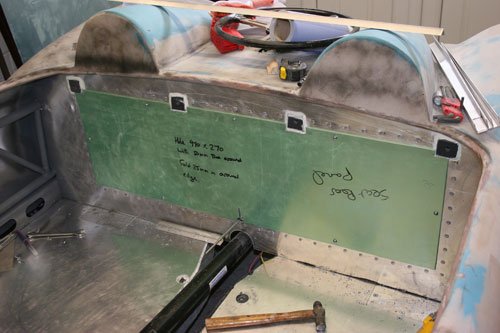
Covered the inside side walls with 1mm ally sheet, i had to join two pieces to cover the whole side due to the total length required and curved following the body shape. Also fabricated panels to the inside of the bulk head to hide the pop rivets used to fasten the engine bay bulk head together.
Fabricated two false inner sills and a tubular ladder frame which I've welded to the front and rear sub frames to add strength to the body.
Part etch primed the area's that would be difficult to reach once assembled.
I was after an ally race style rather than the usual plywood and fabric look, more of a striped back race look to be honest and i think once its painted it will look good.
Just now need to sort the seats out along with runners and a gear box tunnel which will be fabricated from 1.5mm ally sheet hopefully rolled but if that does not work then a box look will have to do.
Started to look for clocks etc so that i can fit the dash board but i am also toying around with the small curved binnacle idea on the drivers side dash area as i was originally going to have a flat straight dash panel across the drivers and passengers side but the curved dash may look more in keeping with the era.
Redratbike Cheers i also like the HOLEY (bless you my son) slots in the inner sills, is adds just that little bit more detail to the interior but also make's people think when they look inside and adds to the illusion.
Paul The side panels are held in by magic..... no sorry about that they are kept in place by making them a tight fit between the top rolled fiber glass cockpit edge which turns out to be a good edge to latch the ally sheet under and at the bottom it sits behind the angle brackets which hold the false inner sill in place plus with being curved also has helps, i also put a few blobs of polyurethane sealer on the inner fiber glass surface to act as a cushion and hopefully prevent any rattles in the future.
Ive taken a photo looking down onto the side so you can see the body curve outwards which helps to keep the ally sheet in place a bit like a spring.
Keep the faith in your build Paul as it is coming along great, the boot lid looks the dogs bollocks.
Been busy making the bonnet stay out of stainless and will post pictures once finished.
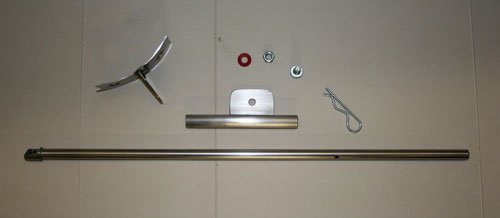
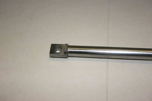
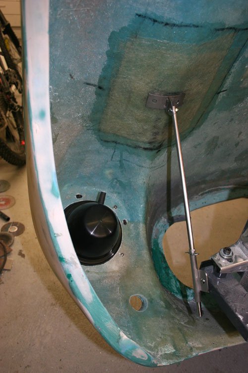
Finished the bonnet stay, its made from two pieces of stainless tube one that slides inside the other, an end pivot turned/milled and tig welded in place. The weld I've hidden by drilling through one wall of the tube then back filling the drilled hole with weld through to the machined end fitting and filling flush, it acts very similar to a spot weld and keeps the tube tidy.
All the parts required.
End fitting turned and milled from stainless.
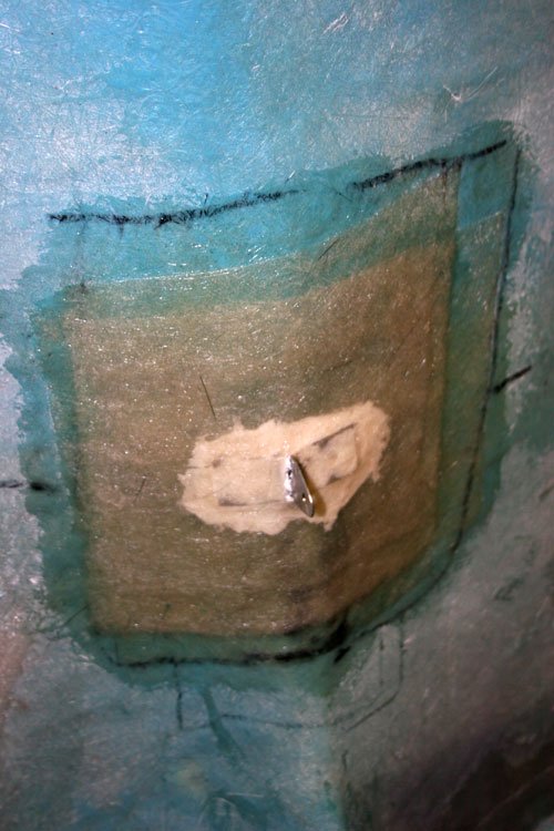
Bonnet stay in position, the area where the stay attaches to the bonnet has had three layers of fiber glass added to add strength and hopefully prevent future fracture cracks but will wait and see.
I intend to bond the top bracket to the bonnet then glass over the area again.
Well that's it for now have to go off to work, see you all soon.
Only managed a couple of hours today due to other commitments but ever little task completed is one closer to being finished.
Bonded the top bonnet stay bracket to the bonnet last night and today covered in two layers of fiber glass for good measure and will give it a light skim of fiber filler to flatten off.
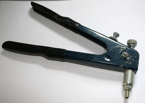
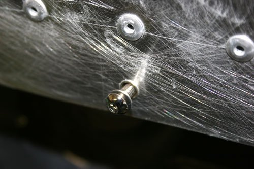
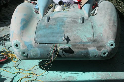
Finally got round to fitting the inspection cover i made many months ago to the rear section, i used captive nut's pushed into a hole then crimped into place with the tool in the first image, they are neat and easy to fit into hollow box section and saves on welding a nut in place.
Rear inspection cover in place.
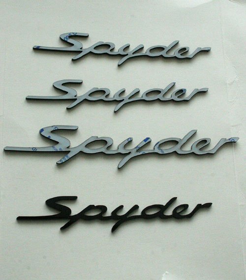
Yesterday i made a couple of badges out of 4mm black perspex profiled on a laser machine, I'm thinking of having one on each side near the front wheel's and the larger one at the rear between the two humps.
Like the alloy interior Swifty, Looking good. Like you say, it does take time, but well worth it.
On the subject of re-registering the build, how long was the time delay between when you sent the docs to DVLC and getting the new ones back?
Paul I also like the spider badge which you can buy on flea bay but the spyder name badge is virtually impossible to buy unless you want to pay a large amount of money so that was the reason why i decided to make my own.
Scottie The paper work was posted on the 26/02/15 and i received the the updated V5c on the 18/03/15 they also returned the original Ribble invoice, the whole process was very easy and went through without any problems which is probably due to all the excellent information on this forum especially from the likes of Paul.
I assume you have not sent your paper work off just yet.
Ive just realized it's exactly one year today when i first posted on this forum and began the build so happy birthday MY BUILD.
Moved onto the rear lights etc this weekend to finish the rear off.
Used the same principle that i used for the front indicators, made a mold lined with cling film from a brown parcel tape center tube then sliced in half at an angle to match roughly the rear wing curve. drilled holes in the area of the wing where the light fits then used fiber filler to stick the pre-made mold to the wing locating with a center screw until dry.
All four light surfaces in place before finishing off with body filler.
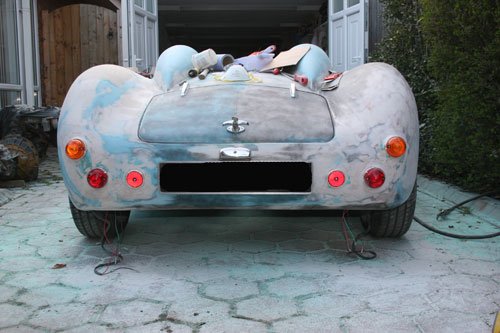
Lights, number plate light and number plate in place.
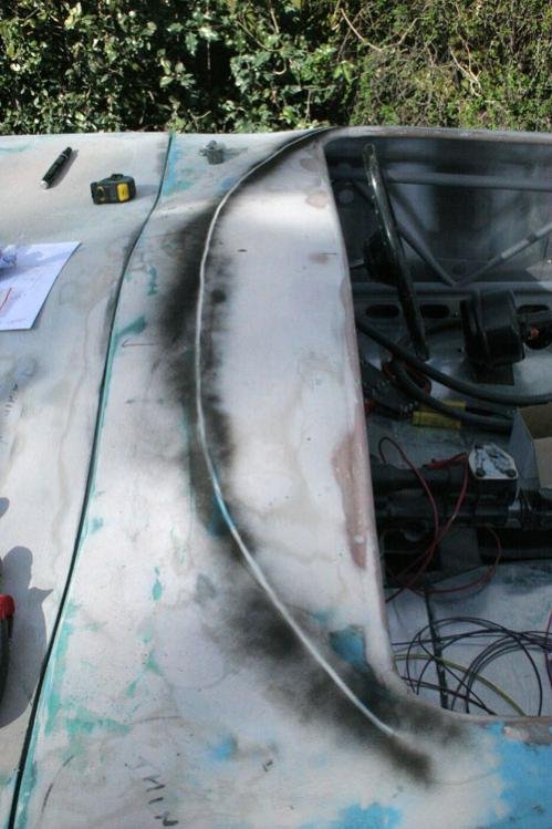
Worked out roughly were the screen will go by laying a piece of cord roughly in place then a quick spray of black paint and hey presto a guide line to follow. Now need to work out how to cut the screen to shape as its a rectangle piece of Makralon and also need to think how to bend the ally screen support i've made to attach the screen to the body along the screen base, will post pictures of the ally support tomorrow.
Grabbed a couple of hours tonight to push on with the screen as the ally trim is now machined to how i want it, will post pictures later.
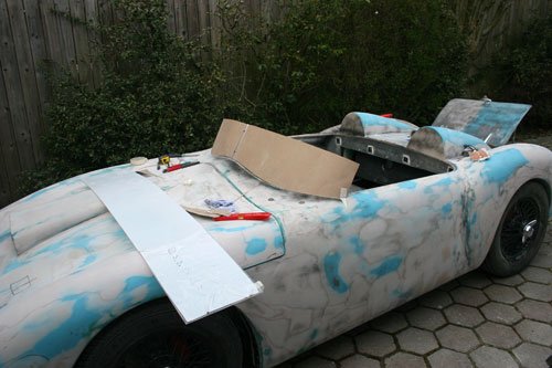
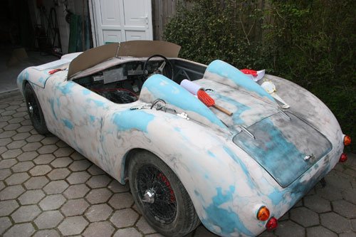
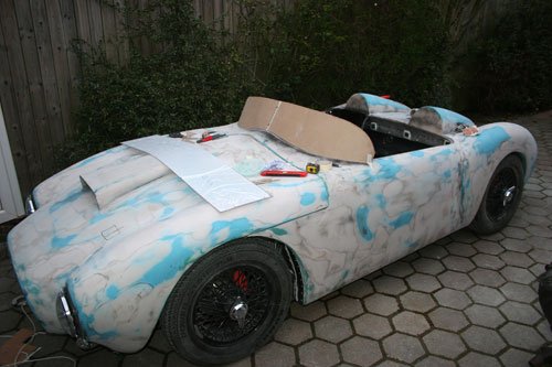
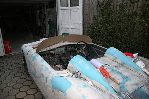
I decided the best way forward with the screen was to make a cardboard template out of cardboard. The cardboard was that thin i had to stick it to the makarlon screen to give a solid surface to work against, i used the top inside edge of the dashboard surface to trace the curves onto the cardboard/screen which worked out pretty close then after cutting out and fitting onto the ally center support i was able to trim away until a good mirror shape was achieved.
First shape to give an idea of how it looked in place, the sharp square ends did not look right so a little more trimming required.
So i trimmed the corners back to give a more sleek look but will more than likely trim some more once i,ve fitted the screen base trim i made earlier. all in all the car is now starting to take shape, roll on the summer and hopefully i will of finished.