This is a read-only archive of the old Madabout Kitcars forum. New posts and replies are no longer possible, but every thread is still here to browse and read.
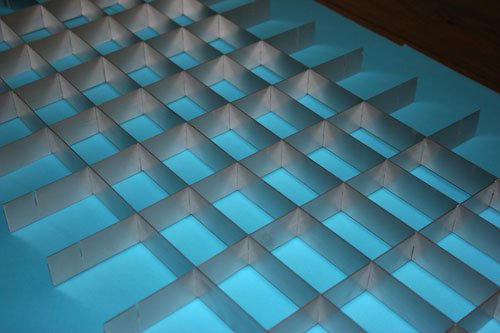
Progressed the grill some more tonight, cut all the slots and roughly assembled, the next move is to make an oval frame from 1mm ally sheet for the grill to attach to.
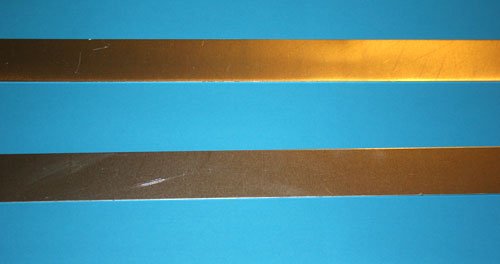
Started off with lengths on 1mm x 30mm sheet.
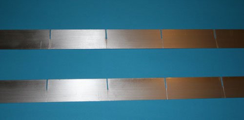
Marked out and cut slots at 75mm pitch on the horizontal bars and 50mm pitch on the vertical bars, each slot was cut 15mm's long which is half way.
A little tip a standard 18tpi hacksaw blade cuts a slot nearly 1mm wide which i then pushed a 1mm thick 12 inch steel ruler down the cut slot to open out to the required 1mm, the hard bit is keeping the slot straight and square may be using a band saw with a guide may be easier.
You then need to de-bur the slot which creates file marks across the uncut section but don't worry as these marks are hidden when slotted together.
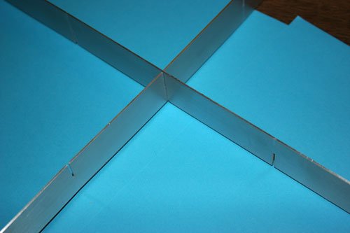
Assembly is by slotting each bar into each other at the point where the slot is cut, this photo shows what i mean. You can see one bar has the slot at the bottom where as the other bar has the slot at the top if that makes sense.
All assembled just need to trim to size and pop rivet to the outer oval ring which i have to fabricate later. It does look good and once anodized it will last years.
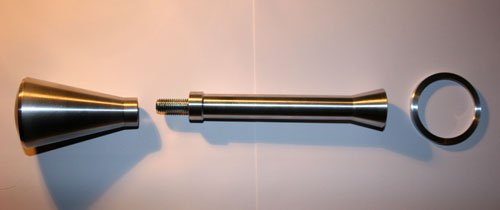
Due to the cold weather i turned my attention to a little bit of turning to tidy up what was a dull looking gear lever from the type 9.
Its made in three separate parts the gear knob, shaft cover with taper end to cover the ball socket of the original type 9 gear lever and a ring.
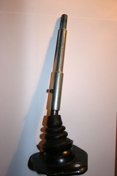
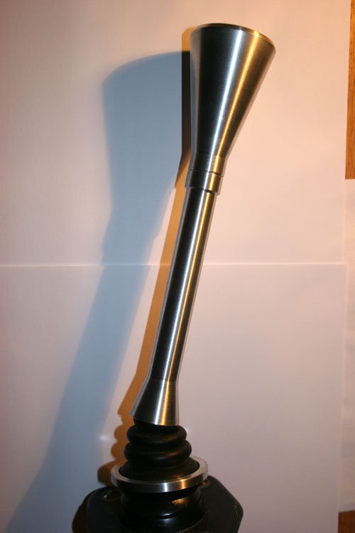
The first image shows the original gear lever with rubber shroud at the base while the second is the new turned ally cover with an ally ring hiding the plastic cup socket at the base of the rubber shroud. I hope to be able to fabricate the gearbox tunnel from ally sheet and for the turned ring at the base of the rubber shroud to sit on top of the ally gearbox tunnel, well that's what i hope to achieve.
Another part made to help with the final illusion and hopefully confuse any body that looks inside.
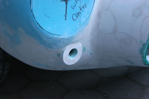
Been mulling over how to attach a tow eye to the front in case the car ever needs to be pulled up onto a flat bed in the future and my solution is to buy a modern screw in tow eye and weld a mount to the front chassis cross member, the tow eye will be long enough to pass through the grill and screw into the mount, once i've finished i post some pics.
Have been mainly filling and sanding over the past two days so my fingers are a little stiff.
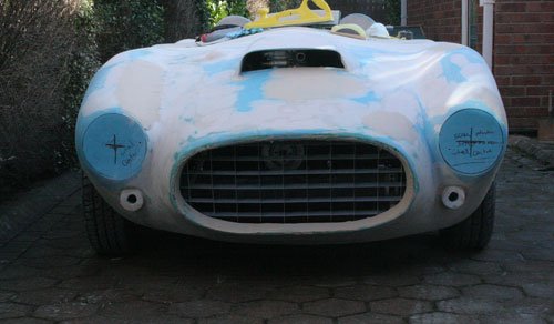
Also trial fitted the front grill before it goes off for anodizing.
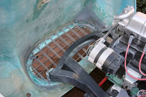
It all went pretty straight forward although i had to cut out one of the tubular bonnet hinge supports to give me enough room to fit the grill, will weld the tube back in once the grill is permanently in position.
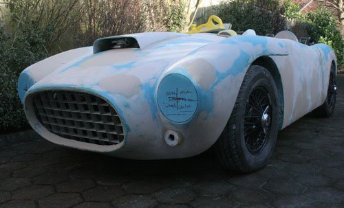
Shot of the grill lying against the nose, i think i will fasten the grill to the body with a couple of angle brackets onto the nose edge i built up with fiber filler.
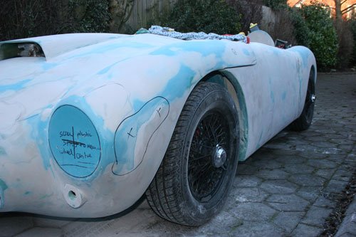
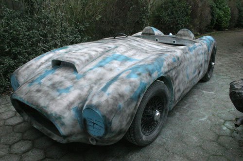
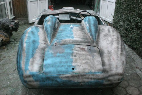
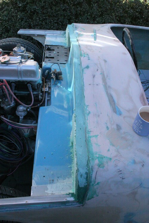
Front indicator mount filled and sanded back, so far i have used over half a large tin of body filler to try and remove the many ripples and imperfections in the shell. You can see from the side shot the area i have covered so far, once the shell is as flat as i can get it with the body filler i will then give the whole shell a couple of coats with Upol Reface then flatten back so hopefully most of the ripples and hollows will be hidden along with any light scratches.
Not a lot of progress of late as i have had other things to deal with so today i tried to make an effort and push the build on.
Gave the whole body a guide coat dusting, used normal matt black paint.
Rubbed the whole body down to reveal the low points and filled over before giving it another dusting of guide coat, it pretty close to spraying the whole body with polyester spray filler which will give me an idea of how the shell really is plus it will then be one colour which helps with the looks.
Attachment “IMG_5142.jpg” from the original forum could not be reliably recovered.
Built up the bulk head bonnet edge with fiber filler so that its 35mm deep across the lip which will be a good surface for the rubber strip to attach too. The original lip narrowed at both sides which looked wrong plus i intended to fabricate an ally sheet bulk head so the parallel lip will be easier to fabricate up to.
Also cut out the fiber glass where the master brake and clutch cylinders go, i've just bought two master cylinders with remote fluid reservoirs.
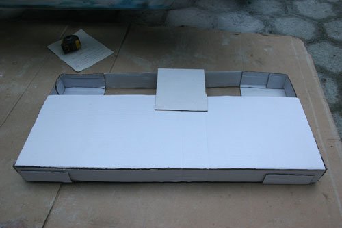
Made a card board mockup for the radiator to see what size will fit and it look's like an RS500 Cosworth rad will do.
It's very tight due to how low i've set the bonnet but hopefully it will be ok, just need to order the rad and make a couple of mounting brackets, then connect the cooling system.
Paul I don't know about overtaking Mac's build as i still have the interior to finish and an ever growing list of things to complete but you are right about the morale boost that one colour gives you so here's looking forward to starting the paint job.
Has anybody fitted a thermostatic fan switch to an after market GT6 engine rad if so what temp was it rated at as i have a choice of several to choose from as follows -
On 88 degrees Off 79 degrees
On 82 degrees Off 68 degrees
On 92 degrees Off 87 degrees
On 88 degrees Off 74 degrees
Has anybody fitted a thermostatic fan switch to an after market GT6 engine rad if so what temp was it rated at as i have a choice of several to choose from as follows -
On 88 degrees Off 79 degrees
On 82 degrees Off 68 degrees
On 92 degrees Off 87 degrees
On 88 degrees Off 74 degrees
I forgot to mention i am fitting electric fans to the rad and the thermostatic switch position is at the top of the rad.
As far as I'm aware, the thermostat usually goes at the bottom of the radiator so you're sampling the temperature of the cool water coming out, not the hot water going in.
That way the fan will only kick in if the radiator is struggling to get the temperature down sufficiently on its own. If the 'stat's at the top, it will trigger the fan to come on all the time once the engine's warmed up as the water coming out of the engine will obviously still need cooling.
When sited at the top it may also fail to trigger the fan when needed if there's any drop in coolant level as they don't react to hot air, just hot water.
I can't quite remember what on-off temperatures my fan switch has, I'm sure it's on my build thread/on the road thread somewhere though.
Mr TYour thoughts are correct for the positioning of the thermostatic switch it is at the bottom and not at the top as i originally quoted so only need to find out the ideal on and off temperatures.
Cheers for that one Mr T.
The Kenlow Fan that came with my V8 Berlinetta that I am restoring came with an adjustable thermostat, can be dash mounted I think.
I haven't really looked at it yet, the thermostat has a capillary tube with a very slim bulb at the end which you insert into a hose of choice, thanks to Mister Towed's suggestion I will insert it into one of the bottom hose joints.
Found some useful information today on fitting the correct temperature range thermostatic switch. It looks like you start with a switch with an ON temperature a couple of degrees above the thermostat fully open temperature which is either 82 or 88 to start with and if the fan runs regularly then you fit a slightly higher ON temp switch, its better to start low then increase if needs be to prevent overheating. If the bottom hose is colder than your target engine temperature then it will still cool the engine.
I suppose another solution would be to fit the variable thermostat as 8 valve ed has opted for but what ever system is installed don't forget to switch the supply voltage to the fan via a relay.
I hope to have the radiator installed this weekend all been well.
...I can't quite remember what on-off temperatures my fan switch has, I'm sure it's on my build thread/on the road thread somewhere though.
I've just found that part of your build while looking for something else...
Mister Towed wrote:
...I've also replaced the adjustable thermostatic fan switch with a fixed one, which is much simpler and neater -
I've gone for an 'on at 88 off at 79' switch and mounted it in the bottom hose. This now cuts the fan in at the right moment, just as the needle climbs out from between the two dots on the temperature gauge, has it back between the dots in thirty seconds and then cuts out. Perfect. I'd say that you'd need a hotter switch if you plan to put it in the top hose though, as the water coming out of the block will be hotter than the water coming out of the radiator...
Decided to start fabricating the bulk head ally work.
The bulk head edge that the bonnet sits on has been built up to 30mm wide and the correct height so that the bonnet is flush when closed with the bulk head once the rubber seal is fitted.
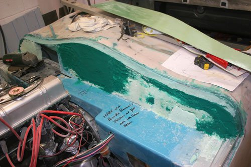
The next step was to fill the vertical uneven surface with fiber filler where the remote brake and clutch reservoirs will be fitted, the rest of the surface was built up with expanding foam so the ally sheet has something to fit against.
Attachment could not be found in the archived database.
The second image is before filling, you can see by how much the original surface curved inwards which would not be a good surface to try and fit 1mm ally sheet to.
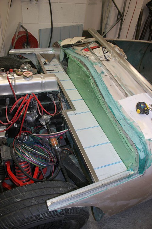
The back plate is pop riveted through the original fiber glass and is made from 1mm ally sheet as it very easy to cut and work with while the base plate is 3mm ally sheet to give a good surface for the various parts to be bolted too.
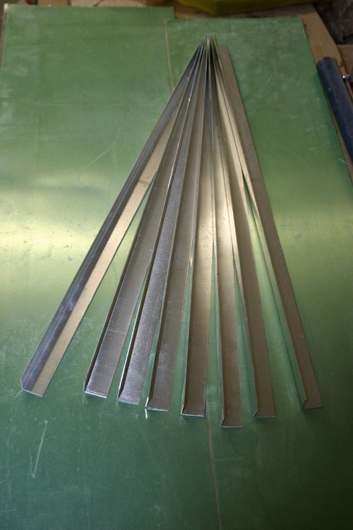
I made a few lengths of angle from 1mm ally 20mm x 20mm to finish the edges,.
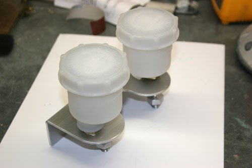
The remote reservoirs for the brake and clutch master cylinders arrived so decided to fabricate a bracket to mount them together on the bulk head.
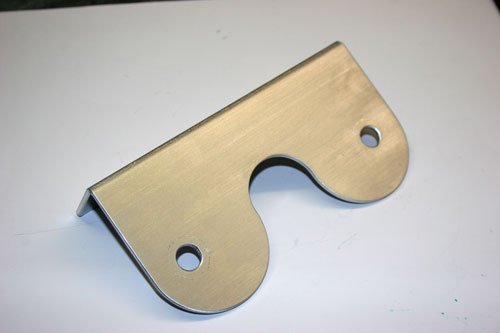
Made from 2mm ally sheet, the holes are purposely off center so that the plastic reservoirs sit centrally to the bracket.
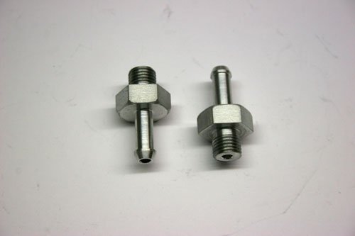
Reservoirs fitted, had to machine the pipe outlet fitting's to suit a push on pipe as they came threaded to screw directly into the master cylinder.
Also machined a couple of 7/16 UNF ally pipe fittings for the master cylinder inlet, will use a dowty seal between the fitting and master cylinder body.
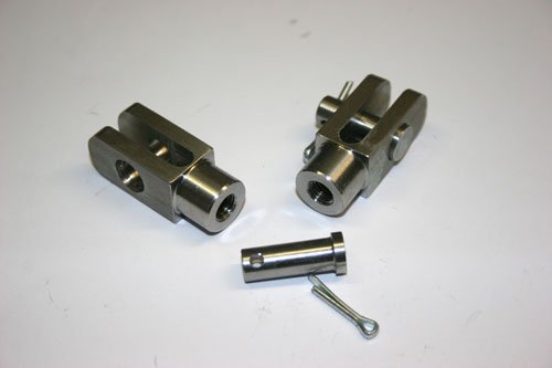
Made a couple of stainless clevis pins for the master cylinders.
Are you sure the 2mm ally bracket is strong enough?I had made them of 4mm and they started to crack due to vibration.
Now made them of 4mm stainless.........
I made the brackets from a soft malleable grade ally which was heated to relive the stresses, thanks for the info so will keep an eye on them once on the road and if they do show signs of metal fatigue then stainless it will be or maybe it requires a couple of webs welding in place.
I did consider stainless but took the easy option of fabricating from ally but may of given myself extra work in the future.
Neat work with the ally reservoirs (just checked your link out), did you do this yourself?
Yes,made them on the lathe from a nice piece of solid ally.
Did'nt like the plastic Jampots which came with the MC.
Ofcourse mine are much heavier as yours so your bracket can be strong enough.
Perhaps a diagonal brace underneath will keep the vibrations out.
René
Not a great deal accomplished over the past few weeks as i have been concentrating on the body filling in all the imperfections and trying to get the curves smooth.
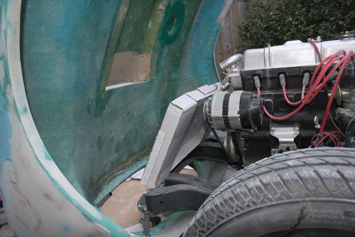
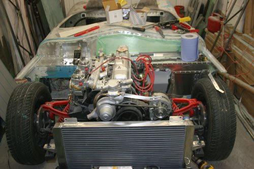
Fitted the ally rad which is over twice the size of the original.
Fabricated two mount brackets to hold the rad in place.
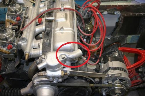
Modified the thermostatic housing so that the feed to the top of the rad is now in the correct position, originally it was pointing to the front of the car now its sweeps around the rocker box which will take the pipe around the back of the alternator.
Tig welded the ally housing.
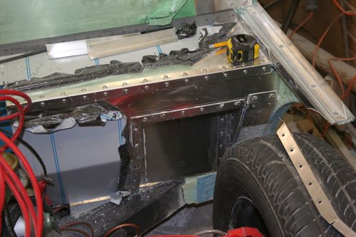
Progressed the bulk head lining with 3mm ally sheet, made the cut outs for the tyres to clear when on full lock.
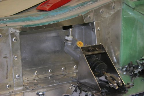
Made a box for the master cylinders to clear the bulk head the only problem now is the fitting for the pipe from the remote reservoir is very close to the bulk head.
Has any body come across a 45 or 90 degree fitting that would allow the feed pipe to clear the top of the bulk head.
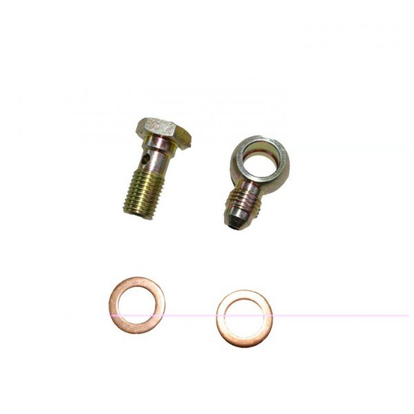
It looks like a banjo fitting and bolt is the solution for the limited access to the master cylinder feed pipe connection, basically something like this.
The only difference is i need a pipe push fit rather than a screw fit on the banjo fitting itself.
Will hopefully have a couple made this week out of stainless steel.