MadaboutKitcars

This is a read-only archive of the old Madabout Kitcars forum. New posts and replies are no longer possible, but every thread is still here to browse and read.

Royale Sabre - Take two!

11 Dec 2018, 8:47pm
A small diversion.....

Thanks JMC for your compliment.

And a belated thanks to Paul L and Patrick who I forgot to thank on my last update.

___________________________________________________________

I had expected to be writing an update on the installation of the engine loom but after a quick trial fit it soon became clear that I needed to fit the gearbox cover first.
So, I need finish off all the bits under the tunnel.
The e36 clutch is notoriously difficult to bleed so I've bench primed the slave cylinder with DOT 4 fluid before fitting in a hope that will make it easier.
I then moved on to refurbishing the gear shifter. Whilst I had trial fitted it before, I had not refurbished any of the worn bushes. The parts are very reasonable prices so I ordered these up....
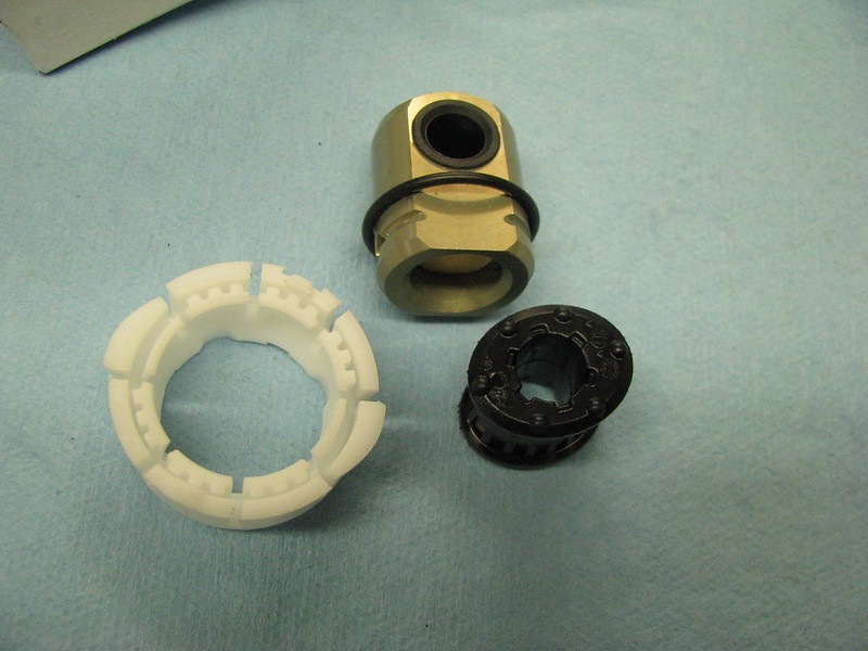
Gear selector refurb parts by Sabrebuilder, on Flickr

When I ordered the parts I forgot that I chose a gear selector from a 318 car as this was the right length for the Sabre. The black bush is for a 328 which is oval whereas the bush on the 318 selector rod the bush is round. The correct part has now been ordered.

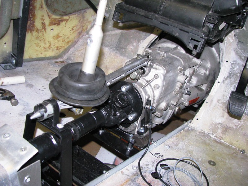
The gear stick sits in a plastic saddle. According to the workshop manual, to remove it you need a special tool to rotate it by a quarter turn anti-clockwise but I found a few taps on a small drift on one of the indents had it rotated and removed in a jiffy.
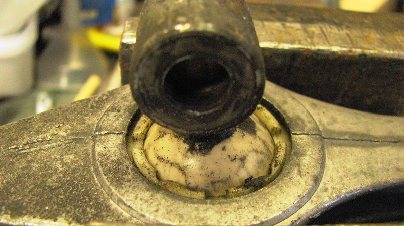
Gear stick saddle by Sabrebuilder, on Flickr

Cleaned up and the new saddle fitted. To refit you just push it in until two tabs click into place. No special tools needed nor the need to rotate it.

Gear stick saddle by Sabrebuilder, on Flickr

The rod joint (as BMW call it) is held on by a dowel pin through the gearbox shaft and the pin is held in place with a spring lock ring. Inside the joint there is a plastic foam pad that acts like a buffer. I'm glad I changed this part as my foam pad had almost disintegrated into a mush of oil and plastic particles. Interestingly, the old joint was made of heavy steel and the new one is a light anodised alloy.

Gearshift rod joint by Sabrebuilder, on Flickr

The final bush at the end of the shifter will be fitted once it arrives.

I'm now working on designing and making a bracket to hold the speedo sensor which will pick up the output shaft of the gearbox, so more on that in the next update.....

....peter
12 Dec 2018, 7:08am
Great stuff, like the first pint of a session. ��
12 Dec 2018, 8:26pm
Barber wrote:
Great stuff, like the first pint of a session. ��


Cheers, Barber :tea:

------------------------------------------------------------------------------

The correct round bush arrived today so I popped down the garage this evening and completed this task.
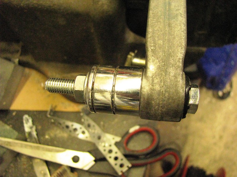
I used the familiar 'socket and bolt' technique that works so well, to first remove the old bush and then to install the new one.

Gear shifter bush by Sabrebuilder, on Flickr

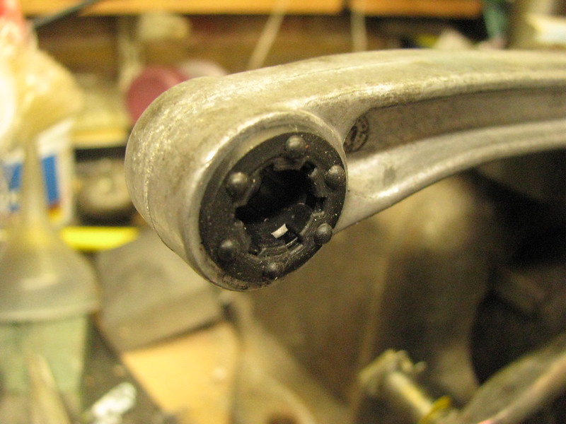
New bush installed....


Gear shifter bush by Sabrebuilder, on Flickr

Subject to Christmas preparations, I hope to have another update next week....


...peter
20 Dec 2018, 9:12pm
Sensing the speed....

My objective at the moment is to get everything around the gearbox finished so that I can refit the gearbox tunnel before installing the engine loom.

So I have turned my attention to fitting the speedo sensor. I decided to use the lobes on the gearbox out flange that has been successfully used on other (Marlin) builds.

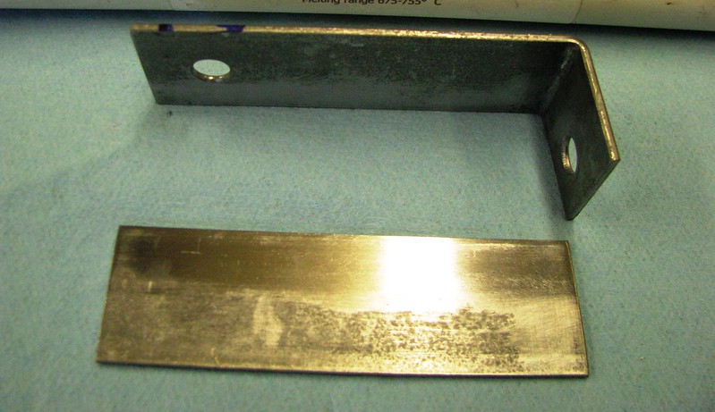
I had to make a bracket to hold the speedo sensor that is rigid to hold the sensor 2mm from the gearbox flange lobes.I started with these two pieces of steel strip that I then welded together.

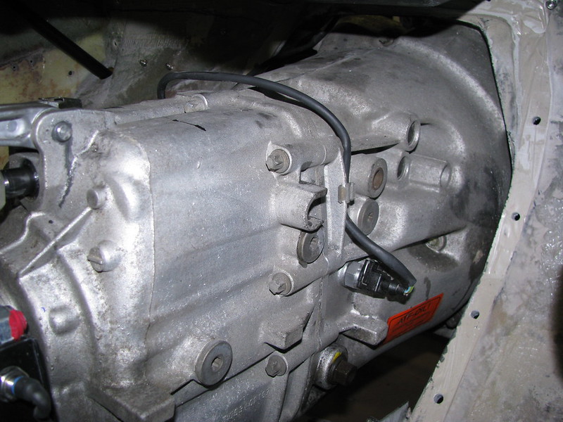
Speedo sensor bracket by Sabrebuilder, on Flickr

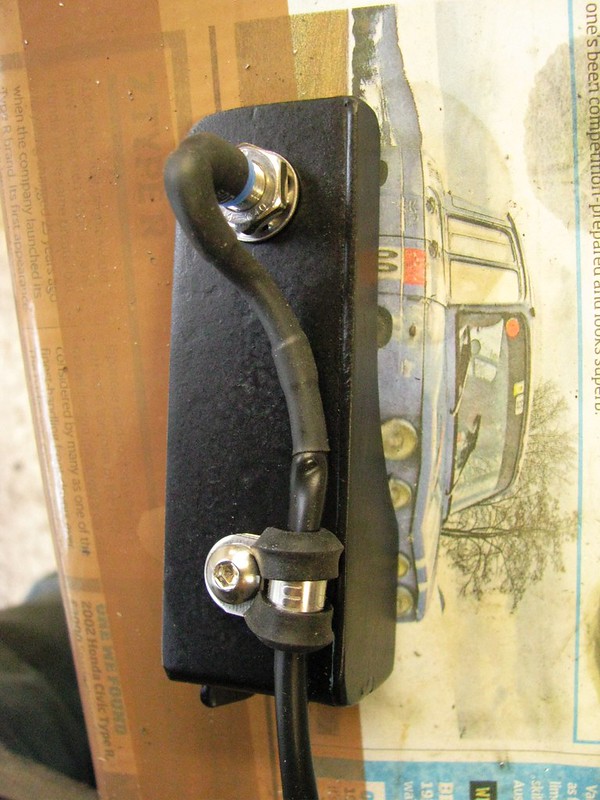
After much fettling and trialing it looks like his. The cable from the sensor is very thin and fragile so to I sheathed it in PVC sleeving and covered the end in a few layers of heatshrink.

Speedo sensor bracket by Sabrebuilder, on Flickr

The speedo sensor bracket is fixed to one of the gearbox mounting points. It is supplied with spring washers but I also used a dab of threadlock to hopefully stop it loosening by vibration.

Speedo sensor by Sabrebuilder, on Flickr

I've painted the gear selector support brackets that I made about 2 years ago and have nearly finished fitting them.

Gearshifter by Sabrebuilder, on Flickr

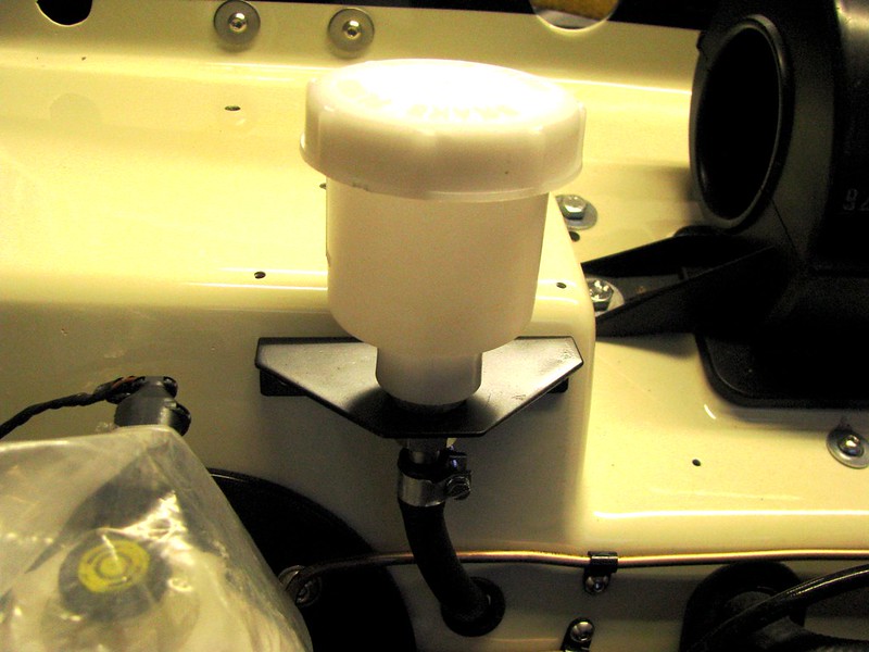
I've also finally fitted the clutch reservoir after painting the mounting bracket. The output ferrule was too large for the hose and there wasn't space for a reducer so I had to the reduce the diameter of the ferrule with a hand file. Very tedious.

Clutch Reservoir by Sabrebuilder, on Flickr

I started to bleed the clutch hydraulics but I found a leak in one of the pipe joints so I had to stop, drain the reservoir and repair the joint. Bit of a 'bleeding mess' so that will have to wait for another day.

So a few small, but very time consuming, jobs completed..........


......peter
13 Jan 2019, 8:56pm
New year, same car.....

With the Christmas celebrations over and the decorations packed away for another year, it was time to get back down my garage.

Picking up where I left off before the holiday season, I refilled the clutch reservoir and first confirmed I had successfully fixed the leak I had.
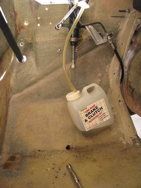
It's recommended in the BMW Bentley workshop manual to remove the clutch slave cylinder and mount it vertically whilst bleeding the air from the system.

Clutch bleeding by Sabrebuilder, on Flickr

Following re-installation of the slave cylinder I confirmed I had a fully operational clutch and to check I had no further leaks I left it for a couple of hours with a piece of wood jammed against the depressed clutch pedal. All good :high5:

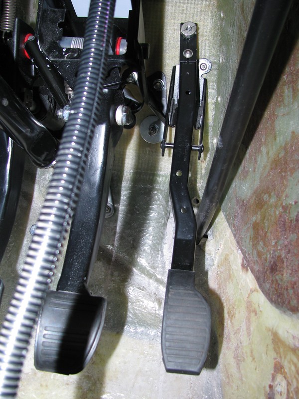
To prevent damage to the clutch master cylinder I made up this pedal stop from a 10mm bolt and a scrap of steel tube.

Clutch Pedal stop by Sabrebuilder, on Flickr

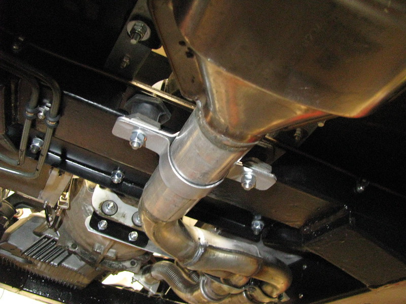
Back in October last year I made up an additional exhaust hanger but every time I saw it in the garage the less happy I got with it and the last thing I wanted was to turn up at the IVA test centre with a detached mounting.

Exhaust bracket by Sabrebuilder, on Flickr

So, I had to do something better and I then spent a good few hours remaking a new exhaust bracket.......
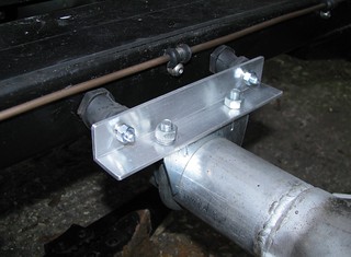
I started by making a two part strap from 2mm thick steel strip which was quite a challenge with only a vice and a lump hammer :-). I used an off-cut of exhaust pipe as a former.
This was then fixed to a piece of angle bolted to the chassis with some substantial exhaust bobbins.

Exhaust mount by Sabrebuilder, on Flickr

In all, with painting and fitting, it took me a couple of days but I am glad it is now done.

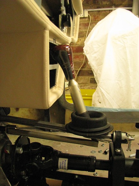
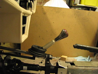
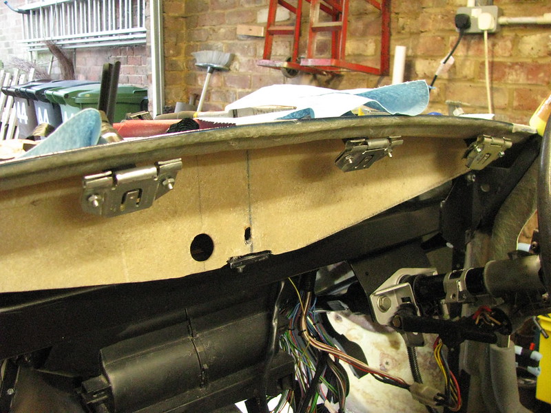
Moving on, before fitting the gearbox tunnel I thought I would check the clearance of the gear knob to the dashboard. I retrieved the dashboard surround from my loft and temporarily fitted in position.
Shown here in first gear which is clearly not ideal!

Gear shifter by Sabrebuilder, on Flickr

Luckily, I have collected a variety of gear shifters so I tried a shorter lower rod.
Gear stick in 1st gear position. Now plenty of clearance for my knuckles.

Gear shifter - shorter lower rod by Sabrebuilder, on Flickr

Gear stick in neutral position.

Gear shifter - shorter lower rod by Sabrebuilder, on Flickr

Gear stick in 4th gear.

Gear shifter - shorter lower rod by Sabrebuilder, on Flickr

Perhaps now a little too short but I think this will be OK, but feedback welcome.

Next week I hope to get the gearbox tunnel fitted and start to install the engine loom. I've also been cleaning up the original windscreen wiper gear in preparation for re-fitting, so more on that next time.

peter.......
18 Jan 2019, 9:51pm
looks awesome, I was using a 3.0 Z3 stick in the sportster but I switched to the 2.5 Z3 one. A bit higher but it's made gear changes a lot better.
19 Jan 2019, 7:40pm
Patrick wrote:
looks awesome, I was using a 3.0 Z3 stick in the sportster but I switched to the 2.5 Z3 one. A bit higher but it's made gear changes a lot better.


Thanks Patrick, that's useful feedback as I was only looking at the picture of BMW gear sticks on your website the other day.
Mike G. suggested I used a shorter stroke gear stick to reduce the travel. For the pictures above I was using the gear stick from a 318i (just because it was already fitted to the upper rod). I've now swapped it with my 328i donor car's gear stick which has a shorter throw.
Feels about right now.
21 Jan 2019, 8:29pm
Tunnel finally fitted

This week I've finally re-fitted the gearbox tunnel :eusa_dance:

As mentioned above, before the final fitting, I swapped to a different gearstick which has a shorter throw. I also fitted the cabling for the reverse light switch and drilled some access holes to be able to do maintenance on the reverse light switch and the speedo sensor.

Reverse Light switch by Sabrebuilder, on Flickr

To seal the tunnel I used this non-setting mastic.....

Tunnel sealant by Sabrebuilder, on Flickr

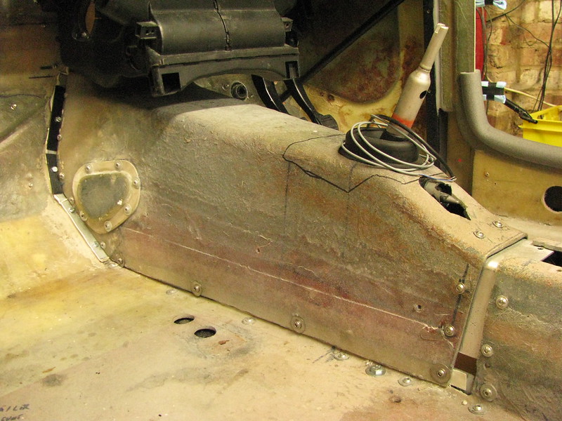
And finally, the least exciting photos.....

Gearbox tunnel by Sabrebuilder, on FlickrGearbox tunnel by Sabrebuilder, on Flickr

The gap between the gearbox and the propshaft tunnels will be filled with a removable fillet.

Not the most exciting update but an important milestone as it means I can now move on to installing the electrical looms :nod:


....peter
29 Jan 2019, 8:12pm
The electrical phase begins......

This week has seen the beginning of the next phase of my build with the start of the electrical installation. An interim milestone will be the re-starting of the engine followed by the completion of all the lights and finally the electric windows! Wiring all the lights will require the fitting of the front wings, etc. and re-starting the engine will also be dependent on completion of the cooling system, fuel preparation, dashboard instruments and the PAS.

So the first step was to 'lay in' the BMW engine loom. The BMW loom is a quite large unwieldy lump of cables and, unlike in the donor car, I'm keeping most it behind the dashboard to keep the engine bay clean and uncluttered.
I cut a 50mm hole in the bulkhead and passed through the injector and sensor, etc cables.

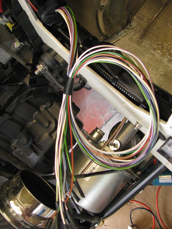
Engine loom by Sabrebuilder, on Flickr

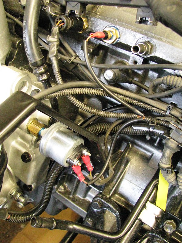
Keen viewers will spot in the center left there is a ETB oil pressure sensor/switch and top left is the additional temperature sensor next to the BMW sensor. And I have connected as many cables that I can at this stage.

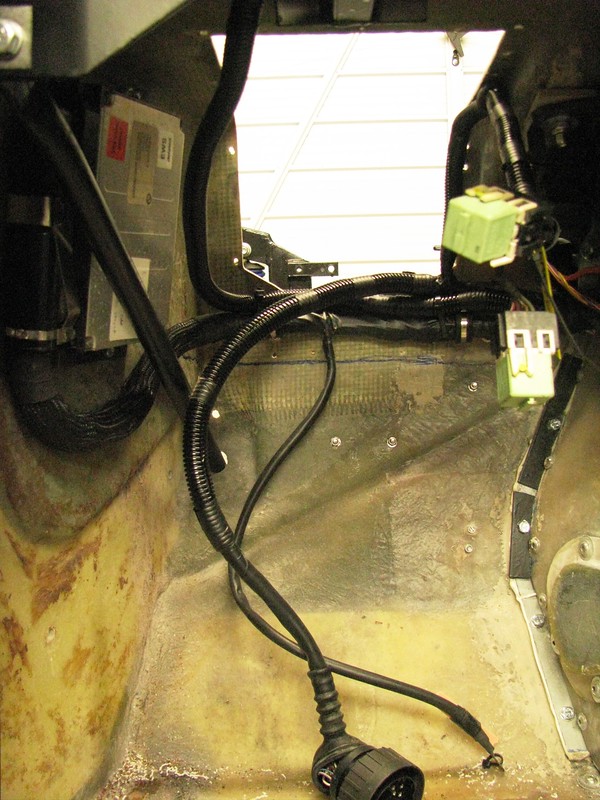
Viewed from the passenger footwell you can see most of the rest of the loom.

Engine loom by Sabrebuilder, on Flickr

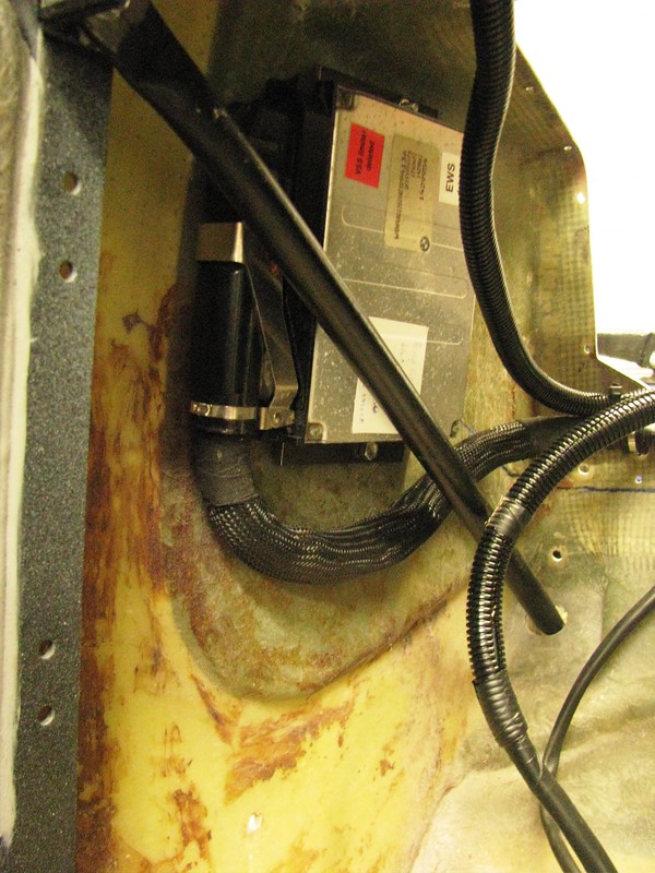
And the location of the ECU was dictated by the length of the loom but I'm pleased the way it tucked away here at the side of the passenger footwell.

Engine loom by Sabrebuilder, on Flickr


Still loads to do, but I'm excited to be getting nearer to running the engine again.


....peter
31 Jan 2019, 5:05pm
Peter - Your build always looks very professional. :cool:

Hope all goes well with the engine start.

Good luck, Paul. :)
2 Feb 2019, 8:14pm
Paul L wrote:
Peter - Your build always looks very professional. :cool:

Hope all goes well with the engine start.

Good luck, Paul. :)


Thanks, Paul.
Unfortunately, progress this week has slowed to a halt due to the sub-zero temperatures.:smow:
10 Feb 2019, 4:25pm
A little progress and a motivational mock-up....

This week I've made a bit more progress on installing the engine loom.

First, I finished wiring up the ETB Temperature and Oil Pressure senders.

Temp and oil pressure senders by Sabrebuilder, on Flickr

The BMW dashboard temperature sender uses two wires but the ETB sensor only uses one (and earth). I have re-purposed the spare wire for the oil pressure sender so I didn't need run an extra cable.

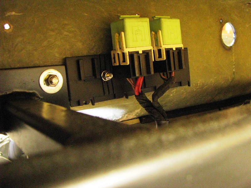
I then mounted the two engine loom relays up behind the dashboard, again really determined by the length of the cables as I didn't want to cut and rejoin when not necessary. I'll need to check i can get to them when the dashboard is installed.

Main and Fuel pump relays by Sabrebuilder, on Flickr

I then had to find spaces for the heater control valve and a megalink fuse so I had to temporarily install a number of parts to check for clearance and space.
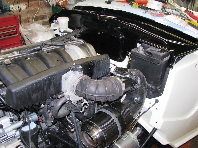
I call this a 'motivational mock-up' as you can suddenly see it all coming together :smile:

Motivational mock-up by Sabrebuilder, on Flickr

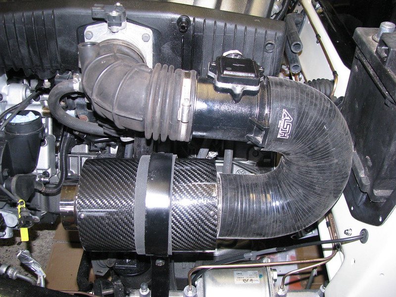
The battery shown here is old one from my wife's car but is just a tad too long, so I'll have to get a shorter one. I've rotated the the BMW MAF elbow through 180 degrees. Then added a 180 degree silicone hose to the Compbrake air filter.

MAF and Air filter by Sabrebuilder, on Flickr

I then got on with installing the heater control valve and the Megalink.

Heater control valve by Sabrebuilder, on Flickr

I had planned to use a Ford Fiesta heater control valve until I read on-line how unreliable they are (which explains why there are hundreds of replacements on ebay). So I've chosen an Audi/VW water control valve. This one is from a 2018 Audi A8. I've also mounted a battery ground point.

I've just ordered up some hose adaptors and heater hose to connect all this up and then I can start re-installing the inlet manifold, etc.

....peter
13 Feb 2019, 8:50pm
Automotive artwork :) very clean.
27 Feb 2019, 8:26pm
A potpourri of fiddly small jobs

Patrick wrote:
Automotive artwork :) very clean.

Thanks, Patrick.


------------------------------------------------------------
Over the last two weeks I've tackled a rather random bunch of tasks some of which have taken a frustrating long time to get right but that's how it goes some times.

So in not necessarily the order I did them....

Accelerator cable.

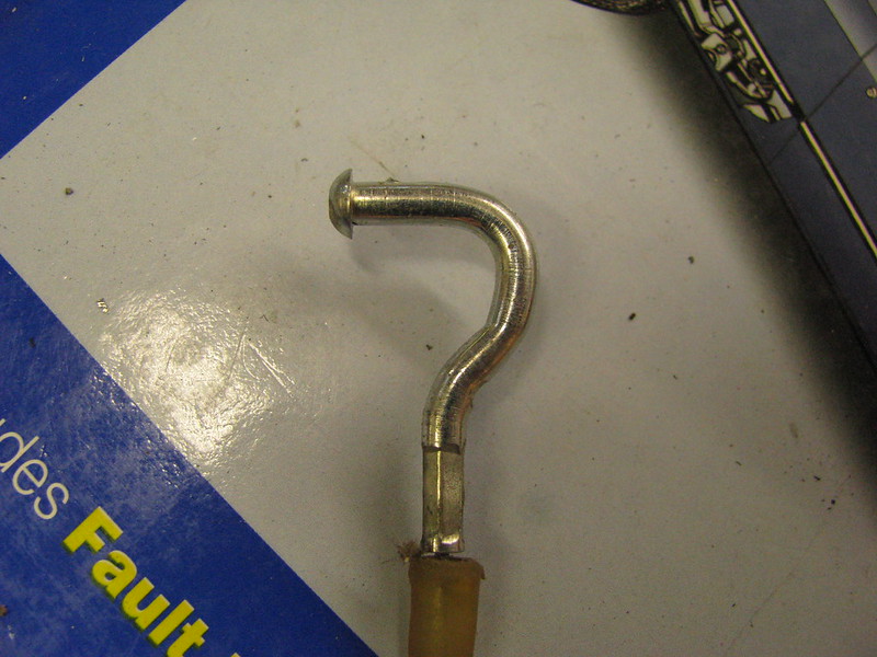
The BMW accelerator cable didn't suit the Ford pedal so I cut the hook off.

BMW Accelerator Cable by Sabrebuilder, on Flickr

To terminate the end of the cable I used this little clamp. It is very secure but I put a blob of epoxy glue on it before tightening it as it is so difficult to get to and I didn't want it falling off.

Accelerator Cable end by Sabrebuilder, on Flickr

I could then install the Accelerator pedal.
Another Houdini act!!

Accelerator pedal by Sabrebuilder, on Flickr

Steering column.

I've reinstalled the steering column and a Ford steering wheel that is IVA compliant.

Steering wheel and column by Sabrebuilder, on Flickr

After years of searching I found a new lower coupling on ebay.

Steering lower coupling by Sabrebuilder, on Flickr

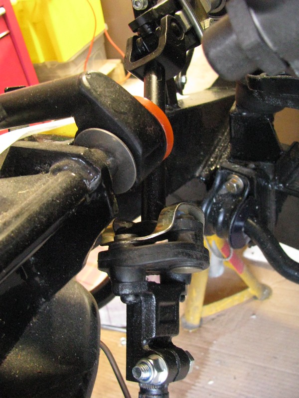
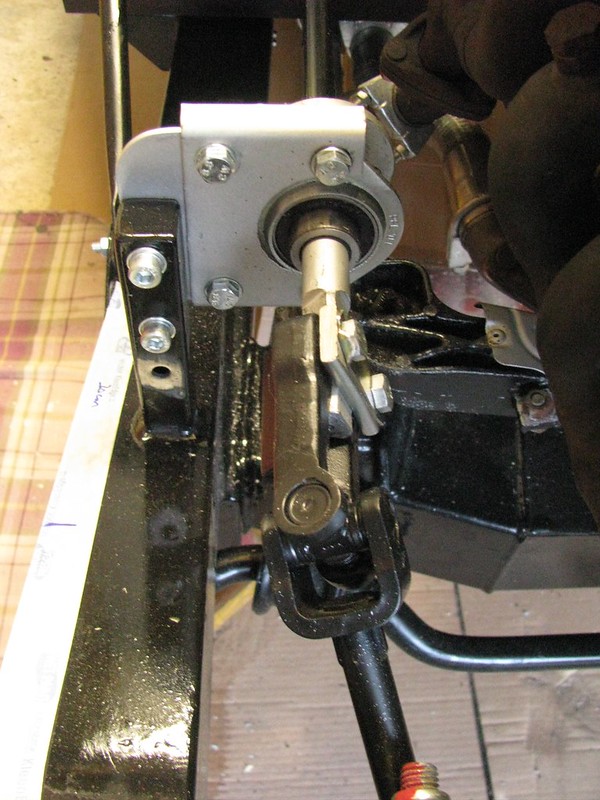
I couldn't figure out why but, the mounting holes in the intermediate shaft needed to be re-drilled to get the alignment between the steering wheel and the steering rack correct.(I spent half a day trying figure out why and then decided to drill the new holes and move on :lol: )

Steering intermediate shaft by Sabrebuilder, on Flickr

Windscreen wipers.

I've mounted the wiper wheelboxes but the wiper motor drive tubes that came installed in the car were made of copper which is not recommended as the copper wears and can be noisy. I've ordered some new steel ones from SVC.

Wiper wheel boxes by Sabrebuilder, on Flickr

It's nice to install the first small bits of chrome bling.

Wiper wheel boxes by Sabrebuilder, on Flickr

Main wiring loom.

I've laid in the Sabre main wiring loom. The crimps in the white connector from the ignition switch, in the center of this picture, were very poor and I had to remake them.

Main wiring loom by Sabrebuilder, on Flickr

Fuse box in the center of this picture. (BTW that's a polythene bag over the bodywork!!)

Main wiring loom by Sabrebuilder, on Flickr

Loads more to do but all these small steps gets me nearer the end goal.

....peter
11 Apr 2019, 7:04pm
Mini update.....

It's been a while since my last update and to be honest I haven't made a great deal of progress due to other priorities.

The wiper motor drive and 'bundy' tubes have been fitted. The original copper tubes have been replaced with steel tubes from SVC who cut and flare them to your specific requirements. It's a messy job as you have to coat the drive shaft with lashings of grease as you assemble it into the tubes and through the wheelboxes.

Wiper wheelboxes by Sabrebuilder, on Flickr

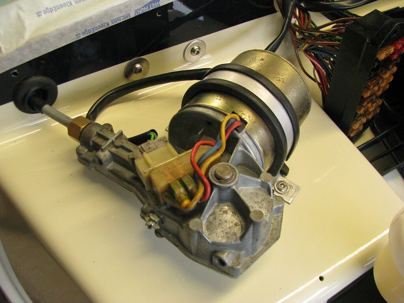
The wiper motor has been cleaned up, re-greased inside and installed. It came fitted with a 110 degree cam wheel but The Royale owners club suggest you should use a 100 degree wheel. I'll wait and see what the sweep is like before investing in a new wheel. It's difficult to test until the windscreen is back in and the wiring is completed.

Wiper motor installed by Sabrebuilder, on Flickr

Unfortunately, the brand new heater resistor pack that I bought was not compatible with the Sabre's loom and heater switch. Luckily I found this used one on ebay from an early Sierra in excellent condition.

Heater motor connections by Sabrebuilder, on Flickr

Back to progress on installing the loom, I've mounted the relays behind the dashboard instruments. I measured to check there is sufficient clearance behind the instruments wiring. The original loom came with relay sockets for indicator flasher, intermittent wipers, main beam and dipped beam relays and I have added two more for the radiator cooling fan and a pair of driving lights. Easy to get to should they ever need changing by just popping out the dashboard.

Relays by Sabrebuilder, on Flickr

Well that's all for now and next update will be in about 3 weeks time.........

.........peter
15 Apr 2019, 8:59am
Relays

As usual, well done, I admire and love what I see you doing. Have a suggestion with regards to the relays fitted to bulkhead above steering column, fitting them facing down, if possible, would mean you don't have to take the whole dashboard with speedo cluster off to reach them, as it would be very tight to reach if faced up.
Keep up the good work.
17 Apr 2019, 4:29pm
Interesting idea, I'll have a look to see if that is possible.
12 May 2019, 9:18pm
Project overrun....

In my last update back in April, I said my next update would be in about 3 weeks so 4 weeks later here I am. My kitchen project has overrun by a week not helped by a loose bath tap that needed to be replaced. But the good news is I should finish off the kitchen tomorrow and I replaced the taps yesterday.

I did find the time to look at Amir's idea of mounting the relays upside-down to ease replacement but even if they were rotated they are still nearly impossible to reach without removing the dashboard which will be a relatively easy operation.

I was also looking at one of my photo's I took last month.
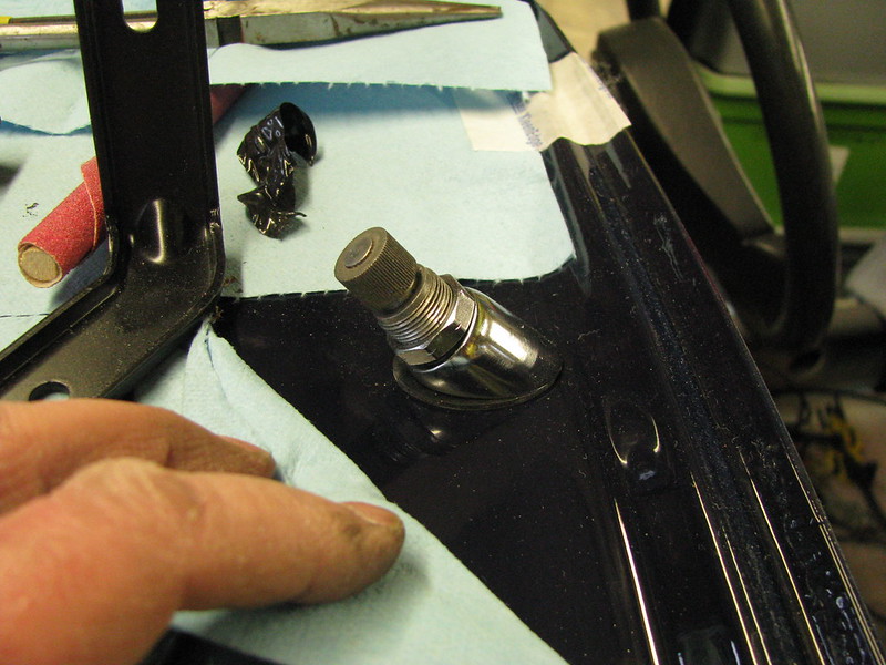
After fitting the wiper wheel-boxes I took this photo.

Incorrect chromed wiper ferrule by Sabrebuilder, on Flickr

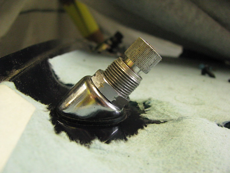
On inspection, I could see that something was amiss. It turns out that there are two different types of chrome ferrules with slightly different mounting angles.
Now here it is fitted with the correct ferrule. Much better but I think I might add a spacer to lower the spindle.

Correct chromed wiper ferrule by Sabrebuilder, on Flickr


I also managed to find the time to fit the BMW engine diagnostic socket which I've mounted inside the glovebox. I've also added a 12 volt socket and a USB 'phone charging point. The hole beneath is so that leads can enter from behind the dashboard without leaving the glovebox door open. Just need to find a nice grommet.

Glove Box by Sabrebuilder, on Flickr

Well that's all for now but hopefully more next week.....

....peter
13 May 2019, 11:47am
Here's a nice gromit for you :D

13 May 2019, 4:00pm
kon wrote:
Here's a nice gromit for you :D


:eyebrows::eyebrows::eyebrows:
25 May 2019, 8:29pm
More wiring.........

I've spent a couple of days this week on the wiring. My main focus has been connecting the BMW engine loom to the Sabre's loom.
But connecting wires is not very photogenic!!

Engine Loom integration by Sabrebuilder, on Flickr

This is the point where I have connected the BMW engine loom to the Sabre's standard loom. When I built my Marlin Sportster I kept what BMW refer to as the X20 connector but in the case of the Sabre I decided it was not really needed. My ECU has been modified so that the BMW EWS is not required. Hopefully, I've connected all the required circuits.

Engine loom - unused wires by Sabrebuilder, on Flickr

These are the left over X20 connections that are not needed. I'll cut them short and terminate them when I'm sure I don't need any of them.

My next task is the brain teaser of connecting the Sierra steering column stalk switches. :icon_eek:

....peter
1 Jun 2019, 8:57am
Misc updates - part 1

So with the spring DIY jobs completed and the garden vegetables all planted I managed to find some decent time on the Sabre this week.
A somewhat random list of jobs completed...

First up I tackled the steering column stalk switches.
Wipers, Indicators, Hazard and Light switch adapter cables were labelled and re-terminated. I wasn't happy with the quality of the OB's crimps and I wasn't sure all the connections were correct so I cut them off and started again. If there are any problems I'm hoping it will be easier to troubleshoot with all the cables labelled with function and loom colour.

Wiring by Sabrebuilder, on Flickr

Wiring by Sabrebuilder, on Flickr

I then installed the switches....

Wiring by Sabrebuilder, on Flickr

Moving on I then cut a hole for the BMW coil pack cable...

Wiring by Sabrebuilder, on Flickr

Taking a break from wiring and now the steering column is fitted I thought I would have a go at an initial setting up the steering alignment. I wanted to do this before any body panels are fitted. With my axle stands used up supporting the car using the axle stands and string was not an option.
So, here's my 'Heath Robinson' way. I strapped two 8 foot lengths of timber to the wheels with bungees. I then set the steering wheel to straight ahead and then aligned by eye the offside timber with the rear wheel. It was surprisingly easy to see very small changes looking down an 8 foot length. I then adjusted the nearside tie rod until the two lengths of timer was parallel. I also checked both timbers were parallel with the chassis rails. It may not be perfect but it will certainly be good enough until I can drive the car to have it set up professionally.

Steering alignment by Sabrebuilder, on Flickr

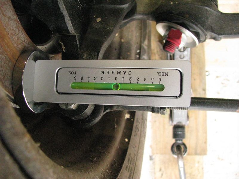
I then checked the camber readings...

Camber - offside by Sabrebuilder, on Flickr

Camber - nearside by Sabrebuilder, on Flickr

Nearside camber reads half a degree negative. An internet search suggests the Sierra spec is 5 minutes positive to 55 minutes negative. So, half a degree appears to be spot on. Offside camber reads 0 degrees. So, within spec but about half a degree different to the nearside. The camber on the Sabre is not adjustable and I can't see any obvious reason for the difference. Maybe manufacturing tolerances of the chassis and upper wishbones?


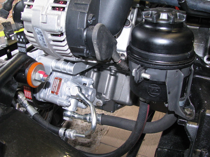
I then installed the PAS reservoir and hoses......

PAS reservoir by Sabrebuilder, on Flickr

.....and I started to connect up the heater hoses.

Heater plumbing by Sabrebuilder, on Flickr

.....end of Part 1, part 2 to follow later........ (off to the St Albans' steam fair today)
2 Jun 2019, 7:30am
Misc updates - part 2

Ok, so here is part 2 of this weeks update.....
So moving back to the wiring I fitted the battery and ground leads...

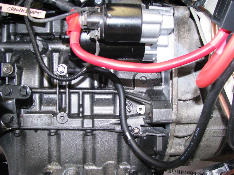
Ground strap to the engine block and the batt+ supply to the starter motor.

Battery leads by Sabrebuilder, on Flickr

...and the battery leads....

Battery leads by Sabrebuilder, on Flickr

and with the cover just resting in place to check clearance, etc

Battery by Sabrebuilder, on Flickr

Then some more bits arrived for the heater circuit....

Heater flow by Sabrebuilder, on Flickr

And finally, I fitted the exhaust flap vacuum reservoir. This was another ebay purchase as my original had a broken mounting bracket.

Exhaust flap vacuum reservoir. by Sabrebuilder, on Flickr

Well that's all for this week.....

........peter
9 Jun 2019, 7:27pm
Misc updates - part 3

Well another week of a miscellany of tasks completed.....

I started with having a go at cleaning out the crankcase breather oil separator but after cleaning it out I found the membrane was perished and split. A new one was ordered.

Crankcase oil separator by Sabrebuilder, on Flickr

I then fitted the ground connection between the engine and the chassis. This is the main chassis ground point.

Wiring by Sabrebuilder, on Flickr

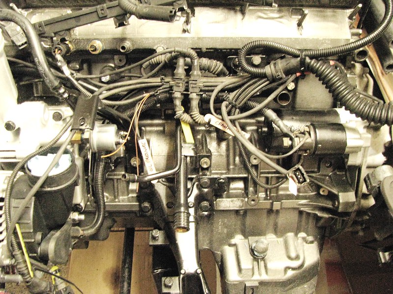
I then started to re-assemble the inlet manifold that had been stripped, cleaned and parts repainted. I refitted the idle control valve and the new crankcase breather oil separator with new seals. The fuel tank breather connection has been plugged as I'm not using it. (centre of the picture). The vacuum hose to the fuel rail pressure regulator is split and perished so will have to be replaced.
Inlet manifold by Sabrebuilder, on Flickr

More parts had arrived in the post so I could complete the heater plumbing hoses.

Heater plumbing by Sabrebuilder, on Flickr

Then back to the wiring, I drilled a hole and fitted the car looms ground connection.

Wiring by Sabrebuilder, on Flickr

Moving on, I started thinking about refitting the camshaft cover. Since the engine has not run for many months I coated the cam lobes with a liberal layer of engine assembly paste to prevent any damage on the first start before the oil pressure is up.

Engine prep by Sabrebuilder, on Flickr

I had temporarily fitted the Inlet manifold to check clearances, etc. I had to modify the bracket under the front end of the manifold as it was just fouling a bit on the oil pressure sensor. A quick mod on the angle grinder and all was good.

Inlet manifold by Sabrebuilder, on Flickr

I've also refitted the dipstick with a new o-ring seal and then fitted the fuel supply hoses from the hard lines up to the fuel rail.

Fuel supply by Sabrebuilder, on Flickr

Good progress last week but there'll be a short pause now while I repair and repaint the grandkids playhouse :biggrin1:


More updates in about two weeks time....

...peter