MadaboutKitcars

This is a read-only archive of the old Madabout Kitcars forum. New posts and replies are no longer possible, but every thread is still here to browse and read.

Mick O'Malley's Moss Monaco

11 Jul 2019, 8:15am
Coffin Dodger Contortions

On Tuesday morning, brimming with enthusiasm, I headed down to the cave to address the list of tasks requiring completion before body mounting. Front and centre of these was mounting the hand brake multiplier, which bolts through the back end of the tunnel. Once this was done I went to connect it to the bar from the lever I'd fabricated, only to find that I'd neglected to drill the necessary hole. Not a problem: I'll just unbolt the lever and drill it on the bench, or so I thought until I realised the nuts in the middle of the tunnel were inaccessible without unfeasibly long arms. Not wanting to invert the newly sprayed body on the grass, which, help being unavailable wasn't an option anyway, I hit on the idea of cutting a hand hole in the table. Lots of careful measuring and the drilling of a guide hole later, I set to with the hole cutter and access was available.


At this stage, covered in sawdust and with aching arms and back, I quit for the day while I was ahead.

Tuesday morning, with the aid of a socket extension, UJ, and contortions, I knocked that part of the build on the head: surprisingly straightforward. Next job: fit the sender to the 'refurbished' Mini fuel tank. This 'refurbishment' clearly hadn't extended to straightening the butchered locating lugs. Despite the once again limited access I managed to tap and bend them into shape and fit the sender. I decided to test it for leaks but then realised I'd need flexi pipe on the outlet stub. I measured this, the metal pipe through the frame and the unions on the mechanical pump, all at 8mm, and bought on line the necessary, including clips.

What next? Ah, the lock-limiting hose clips on the rack to prevent the front wheels hitting the body. None of the clips in my tubfull was the correct size so more on line buying.

The last job for the day was the connections for the water heated inlet manifold. Both the tappings in the water pump housing had temperature gauge senders in them, one of which needed replacing with the stub pipe outlet. Spitfire Steve had come to the rescue once again with this obscure item, handily delivered in the nick of time. The necessary water hose and clips I found and fitted, but I'll need a ½" compression stop end to blank off the heater outlet of my spiffing stainless steel pipe.


I called it a day.

Regards, Mick
23 Jul 2019, 7:42am
Coffin Dodger Conundrum

Mick O'Malley wrote:
Next job: fit the sender to the 'refurbished' Mini fuel tank. This 'refurbishment' clearly hadn't extended to straightening the butchered locating lugs. Despite the once again limited access I managed to tap and bend them into shape and fit the sender. I decided to test it for leaks but then realised I'd need flexi pipe on the outlet stub. I measured this, the metal pipe through the frame and the unions on the mechanical pump, all at 8mm, and bought on line the necessary, including clips.


Following the above, I put eight litres of fuel in the tank and was delighted to find the sender was leak free :). For a reason I'll explain in a later post, I decided to drain it back into containers. Popping the end of the flexi hose into same, I took off the filler cap and - nothing? I removed the hose and blew through it - clear. I replaced it and blew - red face. So, a blockage of sorts. I decided to remove the tank to investigate, this done, and the fuel decanted through the filler hole, I took out the sender and surveyed the interior. Imagine my surprise to see the outlet pipe extended to the inside top of the tank with a filter on the end. Ah, I must need the anti-gravity fuel that doesn't exist. How can this possibly work?

I'm going to fit about ¾ of a hacksaw blade to my padsaw and chop it off to revert to gravity feed unless anyone can advise otherwise.

Regards, Mick
23 Jul 2019, 3:01pm
This is most likely a fuel return pipe. Common practice for carbs with a return system or fuel injection. What car is the tank originally from?
23 Jul 2019, 5:06pm
Hi Jon

Thanks for speedy reply. The tank's from an Old Skool Mini. What I can't understand is how the petrol gets out of it in the first place? I'm sure there's a simple explanation somewhere.

Regards, Mick
23 Jul 2019, 8:53pm
I'm wondering if you've mounted the tank in the same orientation as in the original car?

I don't know anything much about mini's but here is a diagram that shows various options....

http://www.somerfordmini.co.uk/eshop/index.php?main_page=page&id=161


Just a thought .....:noidea:

EDIT: just looked at your tank mounting on page 5 and TBH I can't see anything wrong?
24 Jul 2019, 6:37am
Hi Peter

Thanks! I was beginning to think that I was in an alternative universe. I'll follow plan A with the padsaw: I can't see a downside.

Regards, Mick
24 Jul 2019, 8:36am
Mission Accomplished. Well, One Of Them.....

An early start in the already warm cave saw me digging out my padsaw and a fresh hacksaw blade. It was immediately obvious that the flex in the blade would make the cut difficult if not impossible. After a bit of head scratching I hit on the idea of taping something rigid to the blade to stiffen it sufficiently. I had a length of 6mm stainless rod left over from making the mirror support for the A352 which fitted the bill perfectly. Amazingly, the tank sat on the bench at the optimum angle for inserting the bespoke tool through the sender hole. Illuminating it with my miniature LED torch got me started: two or three minutes saw the cut made, and another couple the offending pipe extricated. I de-burred the inside of the cut with my slimmest round file, and the cut end with my big rasp. I then used my telescopic magnet to remove the filings. Job done :). There's about a centimetre stub left inside the tank, so the dregs of fuel won't flow but this will help prevent any foreign bodies being sucked up.


Regards, Mick
24 Jul 2019, 4:53pm
Mick O'Malley wrote:
Hi Jon

Thanks for speedy reply. The tank's from an Old Skool Mini. What I can't understand is how the petrol gets out of it in the first place? I'm sure there's a simple explanation somewhere.

Regards, Mick


Hi Mick.
The latest version of the "old Skool" mini was fuel injected. SPi (single point) or MPi (multipoint). The tank looked identical to the carb versions except for the fuel return pipe that you have just cut off. The fuel pump was positioned where you have probably put the sender unit. Some tanks also had a vent pipe for use with a non-venting fuel cap and some didn't so needed a venting cap.
Jon
25 Jul 2019, 6:59am
Hi Jon

All is now clear! My tank has the vent pipe. It didn't occur to me that the pick up could be through the sender hole.

Every day's a day at school!

Regards, and thanks again, Mick
2 Aug 2019, 8:24am
Paint and Repaint - Aaaaaaagh!!!

Whist I set about a few of the jobs more easily done with the body on the table, I'd left the mudguards, bonnet etc. down the garden where I'd plonked them after collection. I painstakingly Sikaflexed protective strips to the bonnet opening, left them overnight, and offered up the bonnet intending to fit the locating springs.


Imagine my surprise to find the body was paler than the bonnet! When I'd collected the former, spray dude had mentioned that, as he was running low on the paint I'd supplied, he'd put a red base coat on before the top coats. I'd originally asked him if 2.5 litres of top coat would be sufficient and took his word that it would - poor judgement on both our parts!

On discovering this I immediately ordered more paint and informed spray dude of the problem. Good as gold, as ever, he said bring it down and he'd swiftly do the business. Yesterday I delivered it and will pick up on Monday. Here it sits again awaiting transport, whilst in the cave the lonely table awaits its return.....


Roll on Monday :)

Regards, Mick
3 Sep 2019, 6:36am
At Last!!!

Yesterday, in a rented long wheelbase Peugeot van, I collected the newly sprayed body. Surprisingly, it fitted in the back with an inch or so for padding at each end, a welcome bonus. It's now sitting on the bespoke table in the sunny cave awaiting re-installation of the fuel tank before being finally mated to the chassis.


As soon as I've pressed 'Submit Reply' I'm down there! An outdoor bonus this week is Northrop Grumman B2 Spirits from RAF Fairford passing overhead on 'exercises'........

Regards, Mick
5 Sep 2019, 7:33am
Pitching In - At Last

Tuesday's task was to re-install the fuel tank. When I removed it I noticed that the 12mm ply floor was bowing slightly. I imagined this increasing with the weight of fuel, road bumps etc., until the filler pipe pulled the cap down far enough for it to bind against the body. Having to use water pump pliers on the cap when filling up didn't appeal, so I strengthened the floor by bolting through a length of 1.5" steel angle. Job done.


I'd discovered some time ago that the gearbox cover GRP moulding was too narrow, perhaps it's a version for a Ford 'box as the kit's heritage is unknown? It was hitting the 'box on the driver's side so I cut out most of that side with a panel saw, leaving a little at the tunnel end. Once the body's bolted down I'll fabricate something removable from aluminium.


I Sikaflexed the strip of ply to the bottom of the passenger side to get it to sit at the right height. Nothing seems to fit!

When I saw the Lenham Alfa-Romeo at Prescott Breakfast Club a couple of months ago, I noticed that the builder had come up with an elegant solution to the aeroscreen mountings which didn't use the flimsy castings supplied.


I had bought a small sheet of 5mm aluminium in anticipation of this job so yesterday I set to. I decided to use the existing holes for mounting my supports to keep things simple. Using the tried and tested cardboard assisted design method I carefully hacksawed out the two passenger side supports, and filed, drilled, bent and polished them before bolting in place. As they're at right-angles to their inspirations, I ran an M8 die down the mounting stubs and bolted them through my creations.


Not as pretty as their inspirations, particularly the centre one whose vertical portion needs to be tapered, but passable.

I'm off down the cave to make the driver's side ones now, then to Yate to stay at my kit-car chum's place for our annual dawn sortie tomorrow to the Beaulieu Autojumble weekend. The weather forecast is good!

Regards, Mick
5 Sep 2019, 8:15am
Loving the work, this has to be one of my fav cars on here :)

Mick O'Malley wrote:
I noticed that the 12mm ply floor was bowing slightly.


Have you considered also coating that whole sheet of ply in epoxy? It would add a little more strength, you could also glue the steel L-bar to it while you are at it, but mostly it would be for water resistance. It's the one thing i regret not doing on my last plywood project, as it didnt take much moisture for the ply to start to crack and de-laminate.
21 Sep 2019, 6:58am
Nibbling Away.

Hi Kon, I did consider doing as you suggest, but, as it will never be driven in the rain (in my ownership), and will almost certainly go to France (where it will doubtless be rebuilt) when I pass it on, I didn't bother. Why France? They're mad for Monacos, one of my FB friends even races his :)


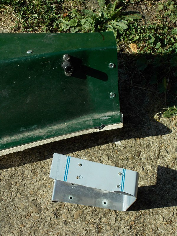
Anyway, back to the build. I turned my attention again to the gearbox cover, the fettling of which is the last job before permanently bolting the body back onto the chassis. Trial fitting it, and bolting it to the front bulkhead by its front flange resulted in a gap where it's supposed to meet the transmission tunnel. I want it to be removable so, after a bit of head scratching, I decided on a bridging piece bolted across the gap using Rivnuts. Being unsure if these would split the GRP I trial fitted one to a scrap body off-cut of similar thickness - success! I cut, drilled and folded the bridging piece using cardboard assisted design, as always.


For those of you unfamiliar with them, Rivnuts are essentially big pop rivets with a splined outside to grip the substrate, and a tapped hole through the middle for a bolt. The gismo I bought for fitting them works on the inclined plane principle (same as a thread, which is an inclined plane wrapped around a rod). Crap photo' alert.


The Rivnut (at the bottom) is passed through the 5.7mm hole and set by tightening the bolt on the right (this is in the finished position) until the end mushrooms. Quite a lot of force is required but the result is a very secure tapping - as long as overtightening of the bolt inserted is avoided!

Gearbox cover and 3mm aluminium bridging piece.


Tunnel with nuts attached.


I'll put two or three more in the top driver's side edge of the cover for attaching its as yet unmade aluminium side, the bottom flange of which will have to be Techscrewed to the wood sandwich floor.

Regards, Mick
21 Sep 2019, 12:24pm
...and again.

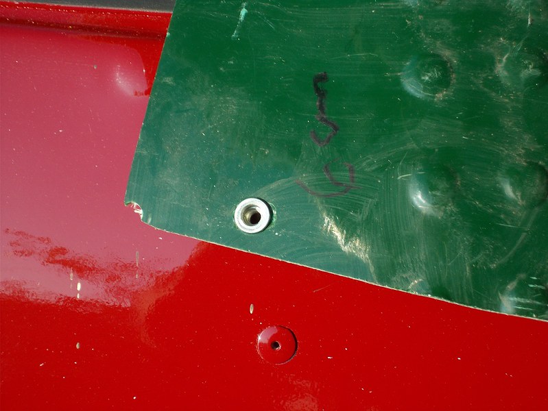
After writing up this week's jobs, I whizzed down the cave and fitted the three Rivnuts mentioned above. I don't think I explained how they're fitted very well, so I took this picture of one inserted in its hole ready for the gismo to mushroom it.


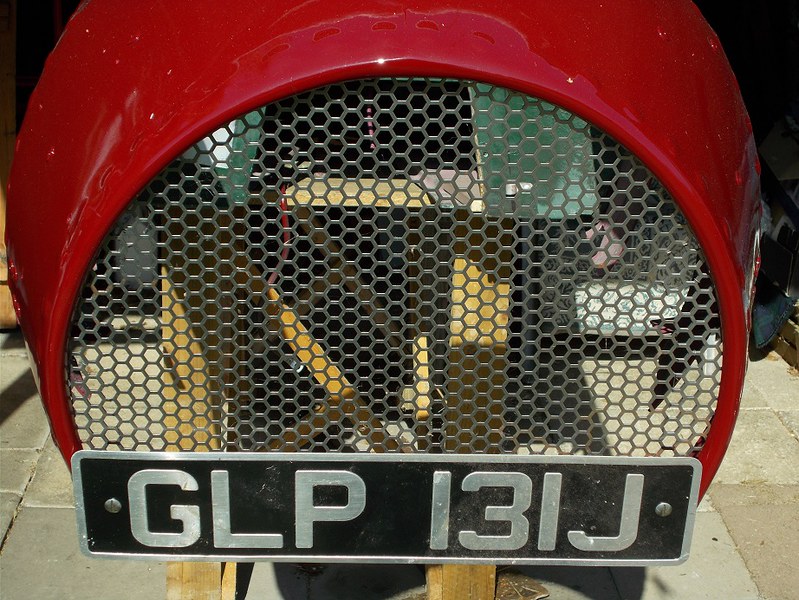
As my son is away until Fri/Sat I can't replace the body so I'm rather scratching for body off jobs. I decided to finalise the grille/front number plate mounting. The former is behind the front lip, but the latter is too wide. After some careful measuring I drilled 6mm holes in the plate for slot headed bolts long enough to hold it proud of the grille, to which it's held with a penny washer sandwich each side. If it drums in use I'll add a third in the middle.


The only other job I fancied in the ever hotter cave was the steering wheel badge mounting. I cut off the protruding stub of column, replaced the nut and lightly ran the flapwheel over it. I found a suitable jar lid and cut a hexagonal hole in it with a small cold chisel so it just fitted over the nut. I Blu-Tacked the badge to it and it to the boss - spot on!


It was held on my Marlin like that for years so should be strong enough.

Regards, Mick
21 Sep 2019, 1:13pm
looking good!
24 Sep 2019, 5:21am
Mick – Your aero screen brackets are certainly a better design than the originals. :cool:

Good luck putting the rest of the car back together.

Cheers, Paul. :)
24 Sep 2019, 5:50am
Thanks Paul,

You have PM (since 21st!)

Regards, Mick
24 Sep 2019, 1:37pm
I would suggest some 'artistic' fillers under the aero screens to avoid a blast coming under it. Looking good!
25 Sep 2019, 6:55am
And still they come....

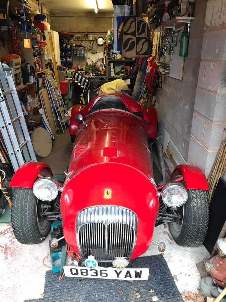
A new member of the Moss Owners' FB group posted these pictures of a newly rediscovered Monaco.


Beautiful.

Regards, Mick
25 Sep 2019, 8:05am
Just imagine, opening the garage door one morning and finding that inside! Would Best Beloved believe that it had just appeared? Or would it be, ' You got another Bl##dy project? It is a bit shiny for a barn find. But yes it is lovely, congrats to the new(?) owner.
29 Sep 2019, 8:41am
Adieu.....

The Monaco will be going to France, where many of its brethren already reside. The vendor is happy with this result.

I can't say I'm enamoured with the grille.........


Regards, Mick
3 Oct 2019, 6:50am
The Mating Season

Yesterday, at long last, good weather coincided with the availability of help. A 17 point turn was once again needed to get the chassis back in front of the body. Without a steering column and wheel this is hard work for a coffin dodger!


Hopefully, this is the final mating of body and chassis :).


I dug out the container of mounting fixings and bolted it down with a smear of copper grease on the threads. All these fixings are A2 stainless so any future dismantling should be hassle free.

Today I'll build the pedal box and master cylinders back in and have a game with my pipe flaring kit.

Regards, Mick
3 Oct 2019, 10:00am
Well done, Mick, it is indeed a great feeling when you get the body on for the final time. :eusa_clap:
5 Oct 2019, 9:03pm
Now what Mick? I for one will miss your reports. Don't be long.
Dave