MadaboutKitcars

This is a read-only archive of the old Madabout Kitcars forum. New posts and replies are no longer possible, but every thread is still here to browse and read.

Swifty's Navigator

2 Jan 2015, 9:00pm
This images shows the look i was after with the bonnet as low as i dared to go, i hope i still have enough room to fit a radiator under the bonnet but by the looks of it it may be a tight fit, it's just a shame the front chassis rails are so close together at the front had they been further apart the radiator may of fitted between the rails.

Attachment “IMG_4995.jpg” from the original forum could not be reliably recovered.
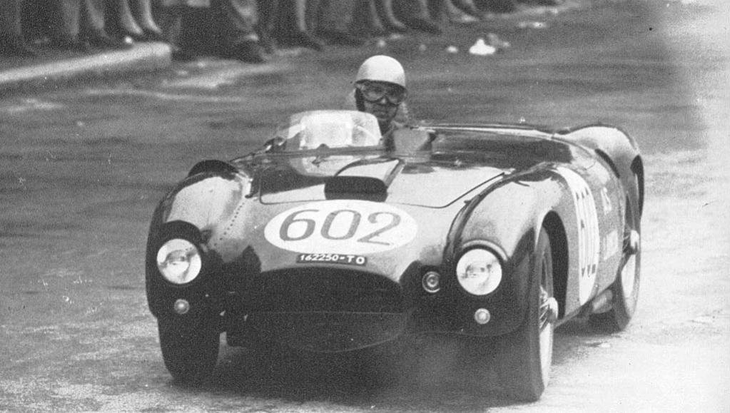
1954millemiglia-albertoascarilanciad24_zpsf6c8f254.jpg


It is starting to resemble the Lancia D24 shape but still are out on final marque.

Well that's it for now, hopefully i will have started the required bonnet edge curve mods tomorrow which can be seen on my previous thread so see you all soon.
3 Jan 2015, 10:31am
Thanks for the link Paul, at the moment i have no brackets on the chassis for a radiator mount so will be looking to fabricating a couple once i know the direction to go, may look at fitting a radiator that is longer than a standard triumph and slightly lower in height but will do a bit of home work first.

There are a couple of guys on this forum using a ford escort radiator or the honda civic which i think gave Mr T cooling issues so may have a look around on one of the triumph forums to see what after market rads they are fitting.
3 Jan 2015, 8:27pm
I was intending to start to re profile the bonnet top edge today but after some thought i think it wise to finish the side panels first and fit the hinge brackets etc so that i can see exactly what is required.

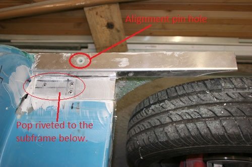
Made two plates out of 3mm ally and welded the locating mounts to the underside of each plate.

IMG_5000.jpg


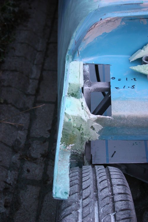
First i marked out and removed the fiber glass to gain access to the front sub frame which i will use for extra strength.


IMG_5001.jpg


Ally plate bonded to the sub frame with bonding paste checked level with spirit level, once the paste cured i pop riveted the plate's to the sub frame below which now has made the panels ridged and strong. The area where the foam is visible will have a fabricated ally plate fitted to match the curve of the wheel arch.


IMG_5006.jpg


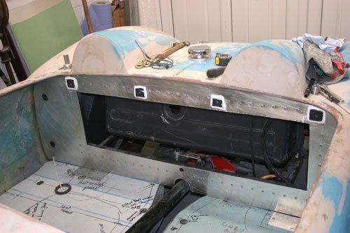
While the bonding paste was curing i fitted the seat rear panel to the rear sub frame with pop rivets, then fitted the petrol tank. Sealed around the edges with panel sealer so once painted will look ok.


IMG_5004.jpg
Attachment “IMG_5005.jpg” from the original forum could not be reliably recovered.


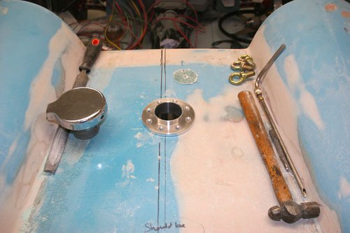
With the tank fitted i could work out where to cut the 52mm hole for the filler cap to go, the ally surround i made slotted in and then the original cap was fitted, a slightly longer rubber hose is required as the original is about 40mm to short plus it is starting to crack.


My next job will be to work out how to mount the bonnet hinges, make a steel hoop and possible fabricate a light weight sub frame for the bonnet to mount to.

Well that's it for now see you all soon.
8 Jan 2015, 8:04pm
This last week i've been busy working out how to attach a couple of hinge's to the bonnet, i decide to machine a couple of ally brackets to start with and bonded a steel tube hoop to the nose section which will be used to weld the support tubes too.


IMG_4897.jpg


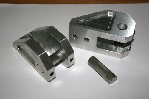
Machined out of ally block with a stainless steel pin with two flats on either end for the grub screws to locate against, it's good practice for grub screws to fasten up to a flat surface so that if the pins needs to be removed the bur from the grub screw is on the flat plus it gets a better hold than if you tighten directly onto the round bar.

A good tip to work out were the flat need to be is to fit the shaft in to position then lightly tighten each grub screw so that it marks the shaft, slacken the grub screw off remove the shaft and file each flat where the grub screw left it's mark. Simpellesssss, i generally use a 10 inch flat file and use the narrow edge (not the normal wide surface) to file the small flat if that makes sense.


Attachment “IMG_5008.jpg” from the original forum could not be reliably recovered.


A couple of steel pads machined to the angle of the front chassis cross member so that each hinge bracket/pivot pin will be inline with each other so preventing each hinge binding against one another, basically its the same principle i used for the boot hinge mounts if that makes sense. The two holes are tapped out to 6mm for the ally bracket to bolt onto.

My next move is to work out how to attach the steel hoop to each ally bracket, will more than likely bend a piece of 20mm steel tube and weld in place.


Well that's it for now see you all soon.
9 Jan 2015, 8:11am
Swifty - I knew it would be worth the wait to see how you planned to hinge your bonnet. :cool:

Whilst I've got hinges a Medieval Blacksmith might be proud of, you are giving NASA a run for its money. :icon_wink:

Good luck, Paul. :)
9 Jan 2015, 8:55am
swifty wrote:


A good tip to work out were the flat need to be is to fit the bar in to position then lightly tighten each grub screw so that it marks the shaft, slacken the grub screw off remove the shaft and file each flat where the grub screw left it's mark. Simpellesssss, i generally use a 10 inch flat file and use the narrow edge (not the normal wide surface) to file the small flat if that makes sense.


It's little hints and tips like this that make this forum what it is, cheers matey and _very_ nice machining btw! :)
9 Jan 2015, 6:14pm
Paul L wrote:
Swifty - I

Whilst I've got hinges a Medieval Blacksmith might be proud of, you are giving NASA a run for its money. :icon_wink:

Good luck, Paul. :)


Do'nt be down on yourself Paul, it's amazing what you'v done with a black & decker drill , a file and a pencil and all whilst battling frost bite :rockon:
9 Jan 2015, 6:34pm
Paul,I totally agree with micky1mo what you have achieved is top notch and is what building your own car is all about finding a problem and solving it.

I served an apprenticeship for four years and now have many more years experience than i dare to remember but i can honestly tell you i am impressed at the jobs you tackle and turn out as this build is not for the faint hart d and thanks for the comment Paul.
10 Jan 2015, 7:27pm
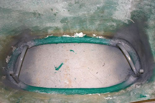
Today i finished both hinges for the bonnet, first the metal hoop was bonded to the back of the nose lip with bonding paste and screws to help keep the steel hoop tight up to the fiber glass.

Attachment “IMG_5013.jpg” from the original forum could not be reliably recovered.


Steel hoop bonded to the nose section.


Attachment “IMG_5016.jpg” from the original forum could not be reliably recovered.
IMG_5017.jpg


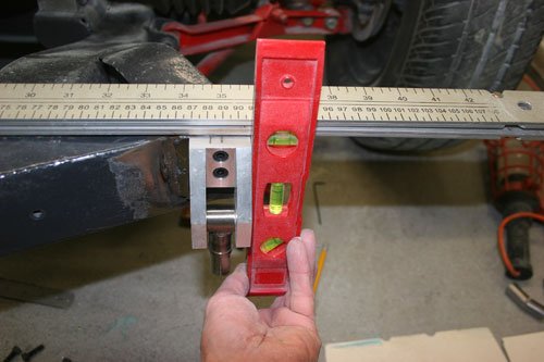
Used a straight edge to align the pads with each other and also for vertical alignment used a spirit level. Once i was happy each pad was welded into position.


Next job was to work out how exactly i was connecting the steel hoop to the ally brackets i made earlier. I decided working with 20mm steel pipe would be the easiest solution plus i had a couple of 6mtr lengths.

Attachment “IMG_5014.jpg” from the original forum could not be reliably recovered.
IMG_5015.jpg


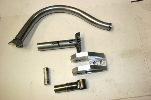
The first image shows all the components for both sides whilst the second is for one side. I turned a couple of spigots to suit the internal diameter of the 20mm tube then tig welded these to each pivot body so that the 20mm tube would slip over them making alignment a lot easier. I cut in half a small length of the 20mm tube and welded these the another spigot which i will use for the other end of the bent tube, the reason i cut it in half was so that the profile matched that of the steel hoop bonded to the nose, i then basically mounted the ally brackets to the chassis lifted the bonnet into position and worked out the length and bends for the connecting tubes which slide on to the pivot spigots and the spigots welded to a piece of the 20mm tube split in half if that makes sense.

Part two to follow.
10 Jan 2015, 7:35pm
Part two of bonnet hinge mods.

IMG_5018.jpg


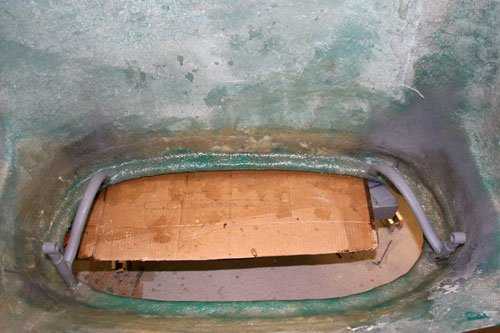
Welded the brackets to the steel hoop and all the joins etc for the connecting bracket tubes. Back filled the area with fiber filler before covering in a couple of layers of fiber glass.
I did trial fit the bonnet to make sure all was in line before filling with the fiber filler in case any adjustments were required but forgot to take a photo.

IMG_5019.jpg


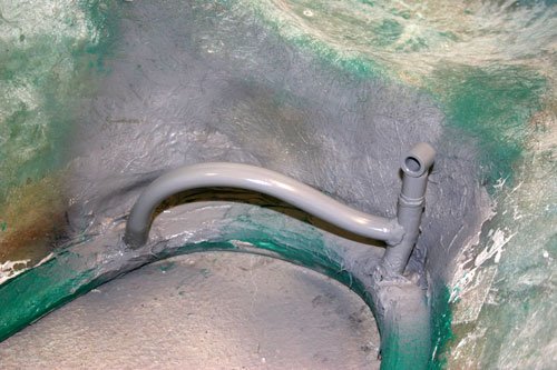
Close up of one of the brackets, i used two connecting tubes to add strength, the bends were made so that the grill will between the brackets without fowling plus i hope you won't be able to see the brackets from the front of the car once the grill has been fitted.

IMG_5020.jpg


Two layers of fiber glass used, once dry i will rough sand over then cover with body filler to smooth over for better presentation.


Well that's it for now see you all soon.
12 Jan 2015, 9:19pm
Attachment “IMG_5021.jpg” from the original forum could not be reliably recovered.


Bonnet attached to chassis with stops welded in place to stop the front valance from fowling the chassis.


IMG_5029.jpg
IMG_5030.jpg


Started to think about how i am going to cover the holes in the bonnet, which are bespoke so i decided to make my own molds out of oasis the foam flower arranges use, its very easy to work with and hopefully will do the trick, i cut it to a rough shape with a band saw then sanded with 180 grit paper to give the shape and finish i was after. I am thinking of covering the oasis with cling film to act as an anti bond surface for the fiber glass but this is a bit of suck it and see. The edges will be blended in to a radius with fiber filler once the fiber glass has been bonded to the bonnet.


IMG_5025.jpg
IMG_5027.jpg


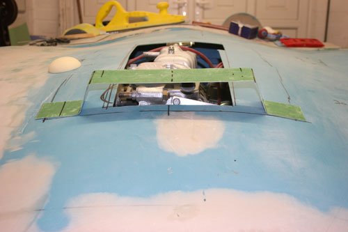
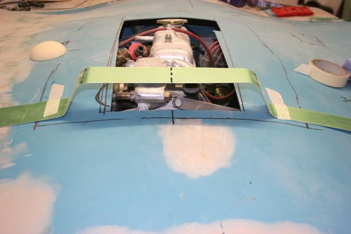
Made a couple of outlines for the main scoop to see what size and shape will look good before i cut and sand the oasis tried one with sharp folds and one with a radius fold, the rear i think will slope back and blend in flat with the bonnet surface.
One area that is tight is the thermostat housing top cover where the two pipes exit, i want to try and keep the scoop as narrow as possible which is making this area rather tight, may have to modify the thermostat housing to drop the pipes down at a tighter angle but if i can get away with it as standard then i will.


Well that's it for now see you all soon.
13 Jan 2015, 8:02am
Swifty - Good to see your bonnet hinge in action. :cool:

I posted a photo of Mister Towed's bonnet scoops & bulges on my build thread yesterday.

There is something about that look that is very "race ready".

Good luck, Paul. :)
13 Jan 2015, 11:11am
Just my ten peneth Tony but bearing in mind there isn't a straight edge on the rest of the car I would go for something with a curve?
Don't want a repetition of the Miglia upside down wheelbarrow fiasco:eusa_shifty:
13 Jan 2015, 12:05pm
Cling film works fine as a barrier to stop the resin sticking to the mould, that's what I used when I made my prop tunnel.

Good luck with the scoops and bulges, Paul and Viatron are absolutely right, these cars can look great with a whole range of additional scoops. Phil J managed with quite subtle scoops and a small bulge on the two he's built (so far), while I needed a much bigger scoop to clear my motor -


My secondary scoop originally cleared the coolant filler, but it's just for decoration now I've added an expansion tank, btw.

Unfortunately, there's also the odd monstrosity kicking about, including the upside down wheelbarrow to cover the V8 fitted to the dragon green Miglia mentioned above. There was also one on ebay that had a massive scoop with holes along the sides on the bonnet that just looked dreadful, although I can't find a picture of it at the mo.

Generally speaking, curves suit the Spyder shape better than straight lines. Having said that, my main scoop has straight sides and a curved top.

13 Jan 2015, 4:01pm
Found it!


:( :( :(

Oh, and the reason Phil was able to use his low-profile scoop design seems to be that his donors both had different engine mounts, making the engine a fair bit lower at the front than mine. With hindsight I probably could've modified the engine mounts and got away without a scoop at all, but I rather like the way my bonnet turned out anyway.
13 Jan 2015, 5:50pm
That really is something special. And, I particularly like the Herald back seat that has been stuffed into the cockpit.
13 Jan 2015, 7:13pm
All i can say about the black sammio is each to their own, i am sure the guy likes it.

My train of thought is much the same as Mac's in that the car is made up of curves so the scoop will emulate this but i can say at the minute the scoop is the least of the problems with the bonnet, the difference in heights between the bulkhead and bonnet is driving me mad. I have made a few cuts here and there but it's looking like i may end up remoulding a fresh new edge which ain't going to be easy:frusty:


Attachment could not be found in the archived database.


This image which i posted a few weeks back clearly shows the difference in shape and height, passenger side is high while the drivers side is too low.....NOT GOOD.


Any way this is what building these cars is all about although i some times wonder if i have been given the rejects off other orders.

See you all soon.
13 Jan 2015, 8:09pm
Swifty - I know I am making hard work of re-shaping my own bonnet, but...

There may be an easier way for you to do it, given the fact your bonnet is the right length.

Here is my suggestion:
- Put some parcel tape along the whole edge of your bulkhead.
- Add some strips of fibreglass matting over the top of the tape.
- Maybe even add some rope/foam/trunking/etc. & extra layers of matting to hold the shape.
- Once set & removed, you will have the correct shape on the smooth underside of this mould.
- Then cut the usual slits in the bonnet and clamp the mould over the top of the bonnet.
- That way you can add matting to the underside of the bonnet so it will hold its shape.
- When that is set, remove the mould and tidy up the slits from the "sunny side".

I hope the above makes sense and that is might be an option.

I just wish I had come up with this idea early enough for me to use it myself. :rolleyes:

Actually I am sure I got the idea from another build on here (maybe Scottie, so I'll just have a quick check).

Good luck, Paul. :)
13 Jan 2015, 9:22pm
I know what you mean about the curves, which is why I went a different route to most and added a bulge instead of a scoop to my old Sammio.


I know it's not a look for everyone, but I was happy with how it turned out :)
14 Jan 2015, 7:33am
Thanks for all the advice guys, it's been said before but this is what makes the forum one of the best, cheers.

I will probably use a combination of both what Paul and Scottie suggests, but will wait for the weather to warm up a little as there's a covering of snow and it's minus out there.

Until next time see you all soon.
14 Jan 2015, 6:57pm
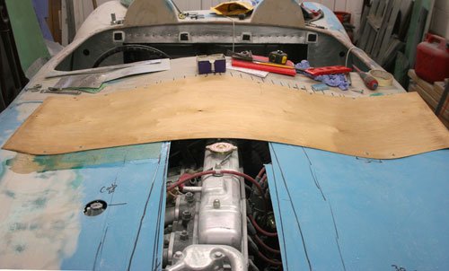
Have come up with a plan of attack for the bonnet edge re-design, today i come across some very thin 1mm flexi plywood which will do the job i think as it's is very flexible without snapping.

I plan to cut out a section of the bonnet from wing to wing and about 300mm's down the bonnet, attach the plywood coated in either brown tape or cling film to the top of the bulk head following the curves then lower the bonnet down onto the flexi ply and screw to the bonnet.
Once in place and happy that the curves have been followed build up the missing 300mm's of bonnet with fiber glass matt finishing off with fiber filler and then body filler.

It's sounds like this approach will work but will have to see how well the ply copes with flexing in two directions both across and down at the same time.

Hope to get this done this weekend all been well, so see you all soon.
18 Jan 2015, 8:22pm
Went ahead with the idea of using the flexi plywood as a mold for the bonnet.

IMG_5034.jpg


The plywood shaped up pretty well, screwed it to the bulk head first then across on to the bonnet making sure it followed the bulk head as close as possible.

IMG_5035.jpg


Once i was happy with the shape i covered it in brown packing tape before adding five layers of fiber glass, i deliberately made the repair sheet bigger than required to trim to size later.

I forgot to take a picture of the glass mat in place so no pictures of that.

IMG_5036.jpg


Once the repair sheet had dried it was trimmed to shape and laid it to position then marked around before cutting the incorrect piece out. I put some large headed screws along the bulk head edge where the bonnet rest's against to act as a position aid for the final height to align the bonnet edge with the bulk head edge.


Section removed ready for the new piece to be fastened into place.


IMG_5040.jpg


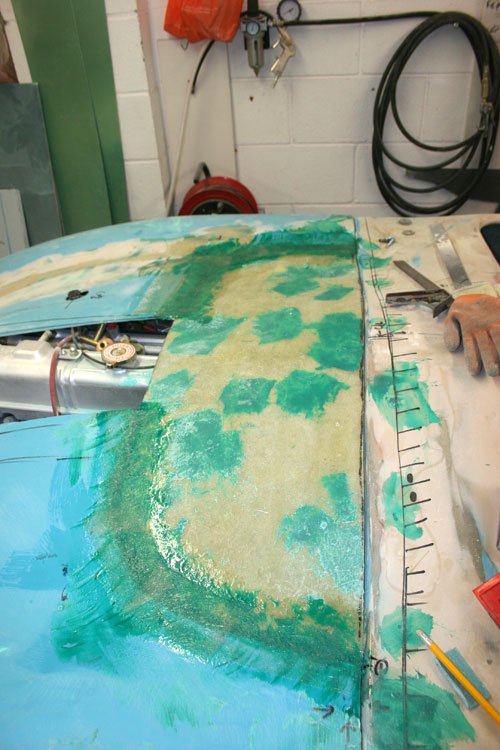
Repair section in place ready to be glassed in on the underside. Made sure all aligned up then removed the bonnet to glass over the underside.

IMG_5041.jpg


Ground out the top surface join to back fill with fiber filler then running one layer of fiber glass matting over the join.
18 Jan 2015, 8:31pm
IMG_5047.jpg


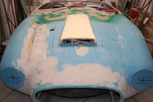
Join flashed over with fiber filler then once dry a layer of fiber glass applied for good measure. I will cover the whole surface in fiber filler then body filler to fill the small imperfections.

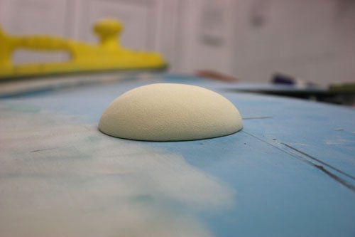
While the fiber glass was drying i turned my attention to the bonnet scoop, I've used a product very similar to oasis as it's easy to sand to shape.


IMG_5042.jpg


Final shape in place, the rear edge will blend in to a seamless join. The top surface curves back wards to follow the line of the bonnet.


Attachment “IMG_5044.jpg” from the original forum could not be reliably recovered.


Covered in packing tape to prevent the fiber glass sticking to the mold.


Attachment “IMG_5045.jpg” from the original forum could not be reliably recovered.


Three layers of fiber glass matting applied slightly over sized to trim to shape once dry

IMG_5046.jpg


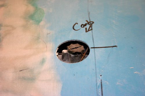
Also covered the small carb dash pot bubble cover in glass matting to trim to size when dry.


Well that's it for today see you all soon.