MadaboutKitcars

This is a read-only archive of the old Madabout Kitcars forum. New posts and replies are no longer possible, but every thread is still here to browse and read.

Another Cordite Is Born ...

8 Feb 2013, 10:04pm
Ended up spending Wednesday afternoon doing domestic chores rather than continuing to work on the car.
Although I did get the chance to do one small job, that was thankfully indoors in the warmth...

Cordite Specific Wiring Diagram:
I cross checked my lighting circuit wiring diagram and thankfully it seems OK, apart from one thing I'd missed.
I had forgotten that the headlight switch is also linked to the lights illuminating dashboard dials & gauges! :rolleyes:
So I have modified my diagram accordingly & will re-print it here when I know wire colours for side repeaters.

I've now started on the wiring diagram for running the engine (something I've already done in practise).

Welding Update:
I had an Amazon gift voucher which I have now used towards a basic auto-darkening welding helmet. :cool:
This will hopefully allow me to see what I am doing before I start welding, which can only help.
There will also be the added bonus of freeing up my left hand from holding the mask in place too.



I'll keep an eye on Ebay for a decent second hand ARC welder for a few weeks, before buying new if I have to.
Depending on what the weather is doing, I will try to get some more practise in some time over the weekend.

Cordite Frame Work Modifications:
And I certainly need the practise as here is my current list of welding jobs:
- Add a "box" to a vertical bulk head frame rail to allow the steering column to pass through.
- Cut and reposition the three frame rails that meet at a point behind the top/front of dash board body work.
- Fix seat belt mounting plates into position, adding additional bracing to frame work where required.
- Extend framework under the dash to provide mounting points to attach the steering column to.
- Match passenger foot well rails so floor pan will sit flush (currently one frame rail is lower than the other).
- Rearrange driver's side footwell rails to allow the pedals to clear the floor pan when depressed fully.
- Reposition front bulk head frame mounting plates to give better alignment with chassis mounting points.
- Add brackets to frame to provide additional support for the battery box when fitted.
- Raise the driver's side lower outside corner bulk head mounting point so that it sits inside the bulk head. *
( * Unless other frame modifications lower body shell sufficiently for this current problem to go away. )

But it is not all welding work, as I have a few simple drilling & cutting modification jobs to do too:
- Drill 2 holes in frame to match original seat belt mounting points in Spitfire hand brake panel.
- Drill 4 holes in Cordite's frame "spine" to allow additional bolting down through main Spitfire chassis rails.
- Remove all traces of the original seat belt mounting plates.
- Remove the body shell fixing bracket on the side of the pedal mounting plate.

That just leaves a few other odd jobs I need to make a final decision on:
- Add a vertical mounting plate to attach the accelerator pedal (might just re-inforce the fibre glass).
- Add mounting plate below dash for choke lever (& maybe hazard light switch & milometer trip reset).

Note:
As always, this is a legacy of the Cordite frame design, which has been re-designed in the Ribble Navigator.

Other Welding Work Required:
- Weld bonnet hinge mounting brackets to front of chassis rails (after re-body inspection).
- Weld the bracket used to pivot the handbrake mechanism back to the panel it broke off from.


Until next time, take care, Paul. :)

Replies:
DonnySoutherner - Cheers Simon, but I think it will be a while yet before I start over taking you.
9 Feb 2013, 8:57am
Looks like you've got a busy morning's work to get through that list. What're you going to do in the afternoon? :)
10 Feb 2013, 8:25am
Another wash out weather wise yesterday & I was doing odd jobs round my mum's house too.

More Welding Shopping:
In addition to the auto-darkening welding helmet, I've picked up / ordered a few more bits...

Some welding gloves...


A book on welding (despite the title it was recommended as a good book for beginners)...


Some extra clamps...


And some more metal files....


Metal Filing:
I take SeaNick's point about nice welds (see his example posted above) reducing the filing required.
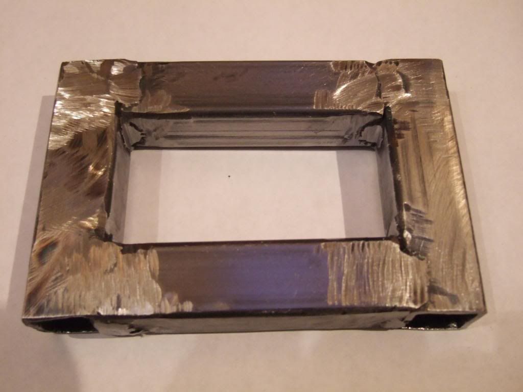
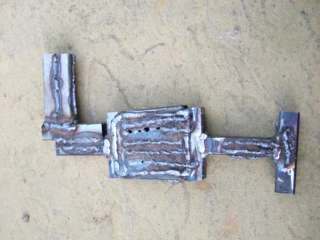
But I wanted to tidy up one of the "boxes" I'd made the other day, just to see how long it would take.
I'd already taken an angle grinder to the flat outside edges, but this wouldn't reach the inside edges.
So I sat down with my new files and slowly, but surely, got rid of the excess metal on the welds...


I know I could tidy this piece up some more, but this is really just part of my learning phase.
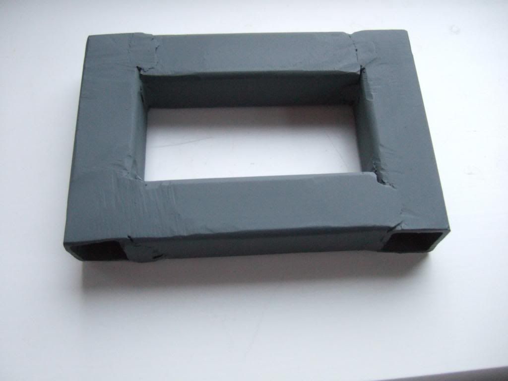
So I gave it a quick coat of primer to see what difference that would make to it.


I know I have a long way to go, but this little piece does give me real hope. :cool:

Next Steps:
Well it is still raining this morning & snow is forecast for the afternoon. :rolleyes:
But if I can take a few measurements, there is some more parts shopping I can do later on.
Other indoor activities will also include working on my wiring diagrams.
Plus I've another idea for shaping my front indicator mounting, but that does need me outside for a bit.

Cheers, Paul. :)

Replies:
Mister Towed - Half a day's work my ar$e! :icon_wink:
I did re-read your first attempts at welding and it is great to see how far you have come. :cool:
10 Feb 2013, 9:23pm
Flap wheels in your angle grinder are your friend when learning to weld!
12 Feb 2013, 7:25pm
There was no escaping the rubbish weather at the weekend, this was Monday morning...


Welding Book:
Whilst the weather has prevented me practising my welding, I've have been reading my "Farm Welding" book.
I can highly recommend it for beginners as it uses lots of pictures to explain the techniques it is describing. :cool:
Especially when it comes to what "good penetration" is supposed to look like on the other side of the weld.
I'm now looking forward to putting some of the book's tips into practise and seeing what difference it makes.

Brake Master Cylinder - A Final Decision:
Much as though it pains me to abandon my Spitfire 1500 tandem master cylinder, it has to go. :icon_sad:
The reality is there is just too much fabrication required to keep it & the work needed would look pig ugly too!

So I am just waiting for the supplier of an upgraded "single line" master cylinder to get a delivery of push rods.
This will allow me to sell my old master cylinder "whole" on Ebay, without providing him with an exchange part.
This is the same part and supplier that Mister Towed used on his build:


My donor came with a spare length of brake pipe which I will now use to join the new M/C with existing pipes.
It just needs to reach a new three way joint where the existing tandem M/C pipes will be re-routed.
( Note: I posted some pictures of this joint the last time I was discussing my options a while back. )
If possible, I'll just bend the tandem pipes into their new position without removing their existing fittings.

Which leads me nicely into another brake related mod I am planning to make…

Brake & Clutch Pedal Mounting:
Previously, DonnySoutherner removed the front sections of his Spitfire clutch & brake pedal mounts.
This was due to the fact there wasn't a big enough gap between the pedal mounting plate & the bulk head.

I've now decided to keep my pedal mounts "whole" & remodel my bulk head to accommodate them instead.
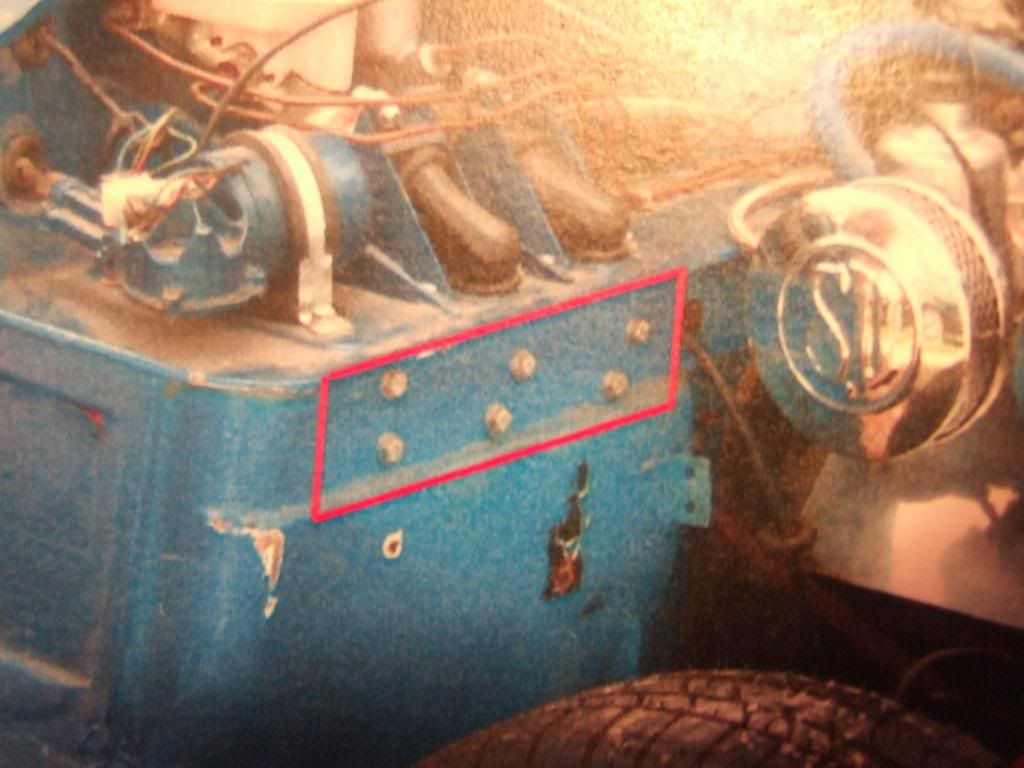
Hopefully you can see the section from the original bulk head that all three pedals were mounted to here.
( Excuse the poor quality, I was taking a photo of a printed photo. )


I intend to cut out a strip from my fibreglass bulkhead equivalent to the red section highlighted above.
Although I need to double check the pedal movement first, just in case this section needs to be deeper.

Once the pedals are mounted to the Cordite framework, this will show how far this section will stick out.
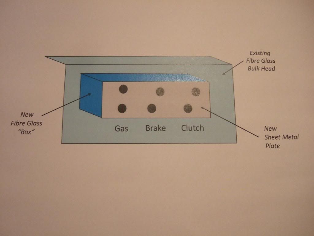
Then I will be able to build 4 "sides" from fibre glass to join the section I've cut out back to the bulk head.

I will also cut out a section of the sheet metal my mate gave me to attach to the front face of fibre glass.
This will provide additional support for the accelerator pedal without the need to modify the Cordite frame.
Time for another Power Point sketch which I hope makes this easier to visualise (as always, not to scale)…


The sheet metal might end up inside this fibre glass bulk head "extension", but I'll worry about that later.
Mounting the pedals will also help me understand the frame mods required to provide pedal clearance.

I might have a go at that over the weekend if the weather holds.

Cheers, Paul. :)

Replies:
DaveCymru - Cheers.
15 Feb 2013, 10:06pm
Cordite Specific Wiring Diagrams:
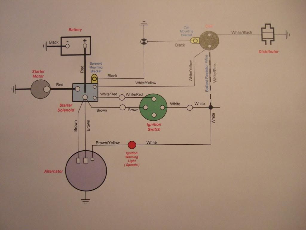
Here is my second wiring diagram built using PowerPoint covering the wires needed to start the engine…


Which corresponds with the minimum number of connections I needed to make in practise, as seen here…


The coil mounting bracket is earthed separately as it is now attached to fibre glass & not metal as intended.
I've done the same thing to the Starter Solenoid, although not 100% sure it needs it, but it wont hurt to do it.

I intend to make just one more diagram covering everything else not shown above, or in my lighting diagram.
This will cover things like the fuel & temp. gauges, overdrive switch, car horns x2, etc.
I've actually found this a very useful exercise in expanding my understanding of how the car is wired up. :cool:

Doors - The gift that keeps on giving... :rolleyes:
I'm hoping Mikmiglia will post some photos of how the doors on his Speedster are set up / work.
As I'm sure that will be a big help in understanding how all the parts are meant to fit together.

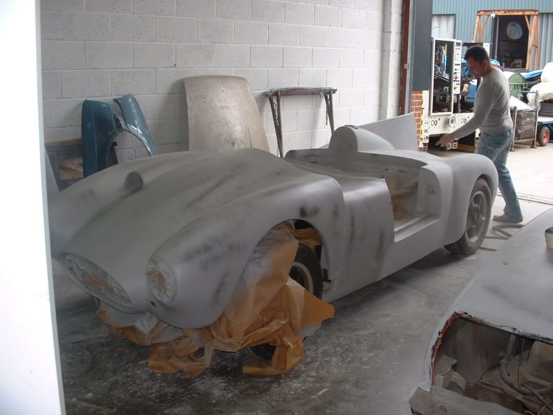
I have resigned myself to a significant amount of work to make the best use of the original Cordite set up.
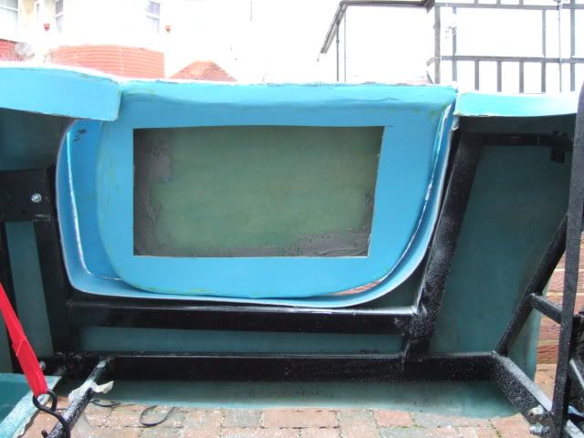
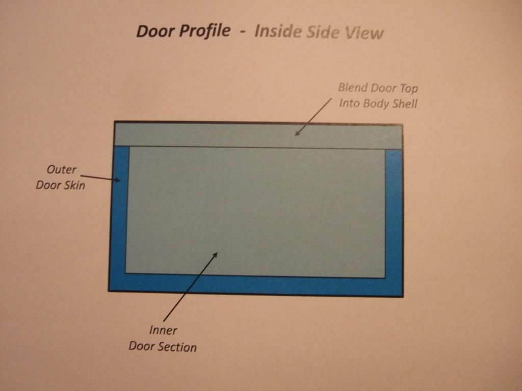
I think I will have to separate the inner door section from the outer skin and re-build everything from there.

I do not intend to change the initial curve from the outside of the body shell leading into the door cut section.
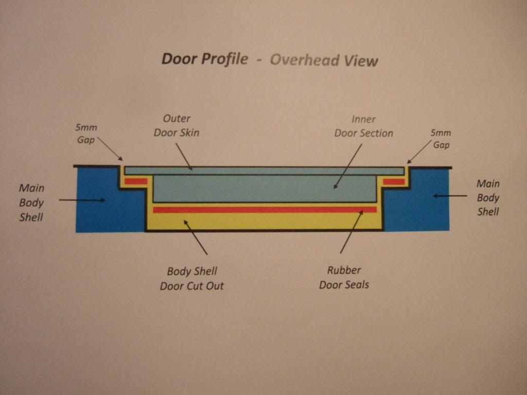
And it should be possible to make the outer door skin fit into this "hole" aiming for a 5mm gap all around.
Although, as previously mentioned, the door cut will need alterations so I can give the body a "shove" forward.

So I had another play on Power Point to see how some of the ideas in my head might work in practise.
Note: The sketches are not meant to be to scale & I've removed all the real curves as they are too hard to do!

I want to go from my current set up of inner door section bearing no resemblance to the door cut out in some places…


To a situation where the inner door section evenly matches the door cut out all round (with curves in real life)…


Similarly, I want the top of my doors to smoothly blend in with the rest of the body work. This is now…


And the inspiration for what a "blended in" door top could look like has been provided by Mikmiglia…


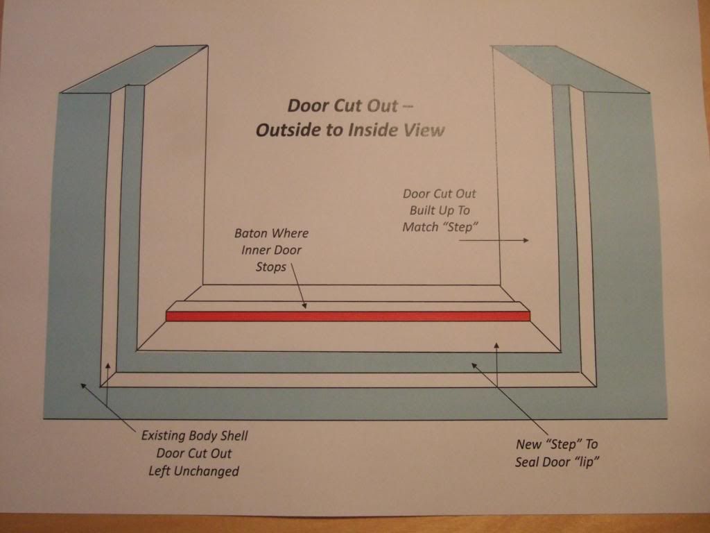
So far, so good, but this work would effectively create a "lip" around three sides of the door "inner".
In which case, I'd expect to have a small "step" in the shape of the door cut for this "lip" to seal against.

Not sure what type of door seal to use, or how to attach it at this stage, but I am open to suggestions.
What do other builders intend to use as a seal on their bulk head for the bonnet to close against?

Anyway, I'll worry about the detail another day, this was my initial thoughts on sealing up the doors…


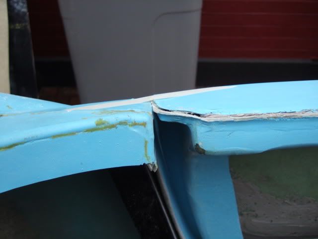
The current inner door section set up is significantly narrower than the width of the door cut out in the body.
It appeared that a "baton" had been used on a previous Sammio build for the door to close against…
( Note: That is what the long red line in the sketch above represents. )


But looking at this photo again, is the baton needed because there is no "step" built into the door cut out?
If there was a "step" on all three sides of the cut out, then the door would simply seal against that.
I included a baton (with seal in red) in this sketch, but have now decided that I don't actually need this….


Don't get me wrong, building this "step" & matching the rest of door cut out to it is a major piece of work.
The only good news is that, as shown above, the first part of the step is the original shape of the car.

So if I can match both outer door skins to their respective cut outs*, they should look OK from the outside.
* The doors will stay as different sizes, there is already too much work needed without fixing this problem too!
Note: Matching doors will be available in the new Ribble kits, as my Cordite door design has been dropped.

Crikey, I'm worn out just describing all the work that lies ahead, and I haven't even started it yet!

Seat Belt Options - More Thoughts:
KISS principles do keep drawing me back to consider a traditional "static" 3 point seat belt arrangement.
I think these would be easier to mount than building somewhere to mount a the retractor belt arrangement.

Mind you, if I am prepared to accept the restrictions of those, I might as well have the "looks" of a harness.
Saw these military harnesses on Ebay & they look the part, just not sure if they would be UK road legal?


Decisions, decisions, is it any wonder this build is going to take me forever and a day to complete! :rolleyes:

Next steps:
If the weekend weather holds, I hope to start work on my pedal mountings & get more welding practise in.

Until next time, take care, Paul. :)
16 Feb 2013, 9:44am
I like the attention to detail you're showing here Paul. It might seem like it's taking forever to build (so's mine), but I find it extremely satisfying to chop and change things until they're just the way I want them.

These cars can be a quick and cheap way to put something different on the road, but for me it's more about freshening up my engineering skills, learning some new ones and excercising my imagination.

A few hours every four or five days is all the time I've been able to put into this project, and it's really starting to come together now. Stick at it and, before you know it, you'll have your car exactly the way you want it.

I'm so glad I didn't go for doors, though... :fear:
16 Feb 2013, 10:58am
Front Indicator Mounting Moulds - Continued:
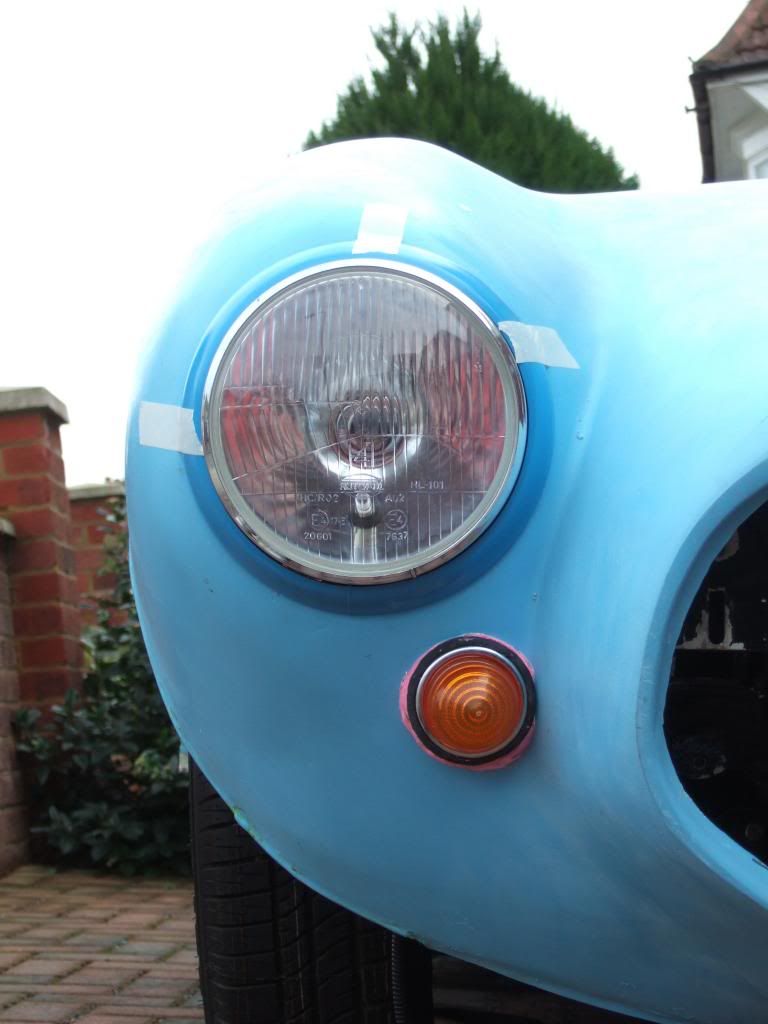
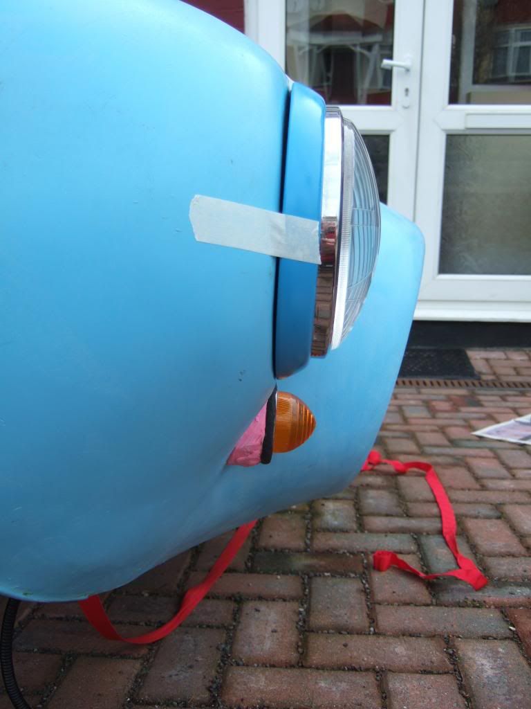
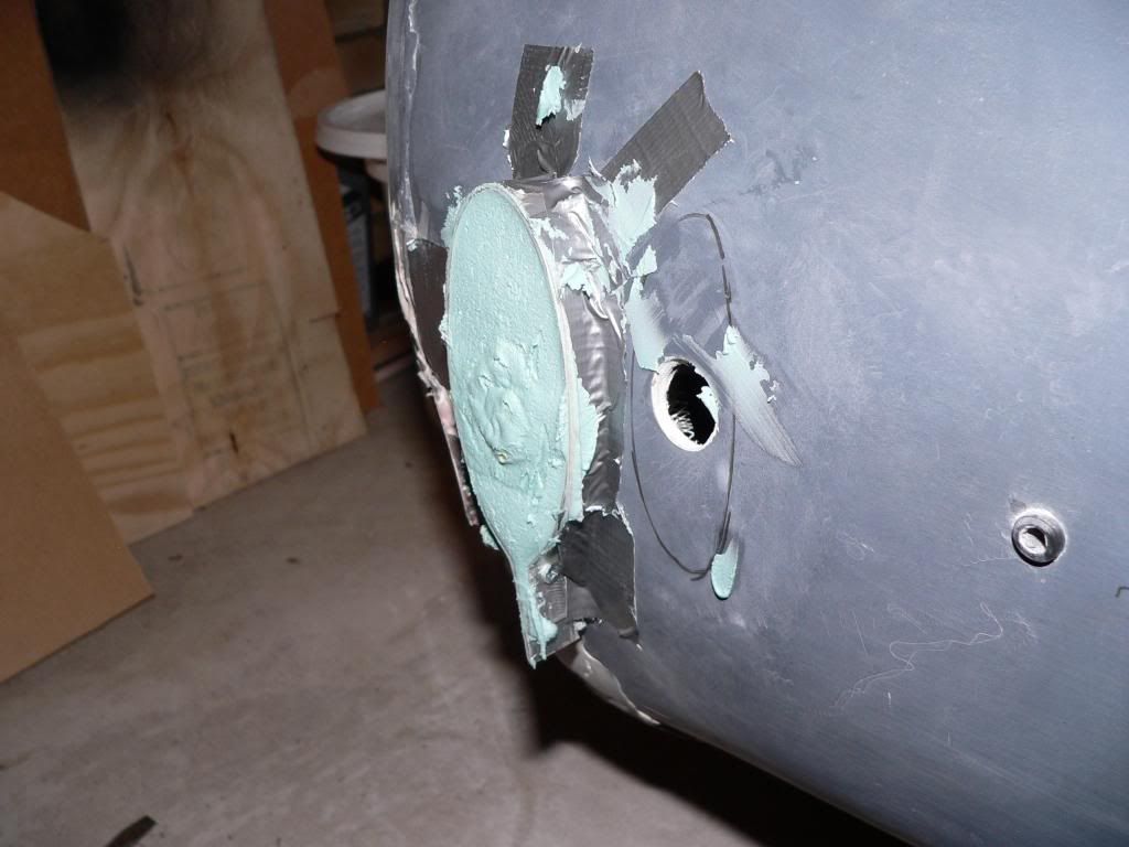
Previously, I'd struggled to shape the back of my insulation foam block to match the contours of the bonnet…


After a bit of beard scratching, it occurred to me that one solution might actually be 'child's play'.
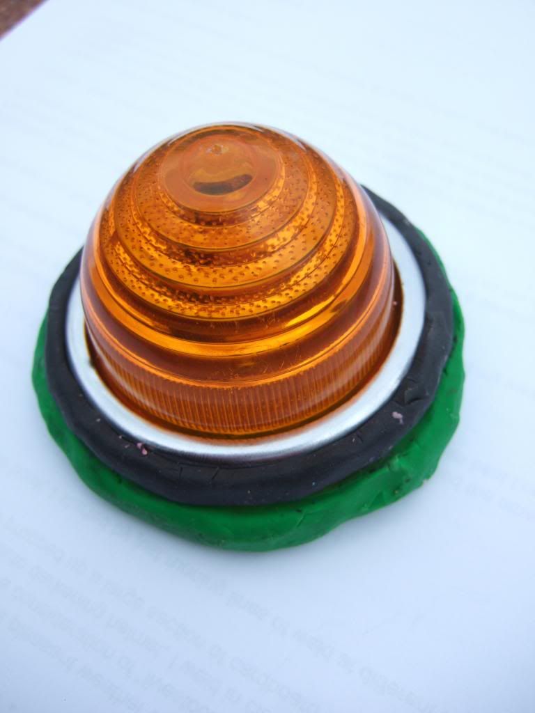
So in my best 'Blue Peter' tradition, out came some plasticine and a pump action toothpaste top. :icon_wink:

The toothpaste top formed a slightly oversized hole equivalent to where the indicator's rubber seal goes.
This "hole" would also mark the centre of the indicator to allow me to position the mound in the right place.

A ring of black plasticine represents the outside diameter of the seal & therefore the size of the mount's face.
The green plasticine underneath was part of my failed first attempt to do this in two stages. :rolleyes:


Eventually I did get a large chunk of plasticine roughly moulded into a position that worked...


And this is the shape of the mould required, about an inch at the deepest point at the bottom...


At this point I was again reminded of sticking to a KISS approach & checked up on Mr T's build.
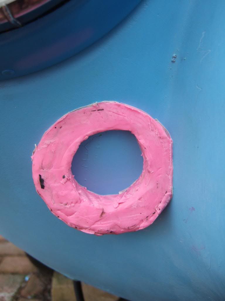
I remembered he had made moulds for his rear lights using filler & I might just do that.


If anyone can tell me why this approach wouldn't work on the front, I re-create this pink shape in foam.

I just need to warm up a bit indoors, as although it isn't snowing, it is still quite cold.
Then I have to do some family stuff, before I can to get a few more car jobs done later on.

Cheers, Paul. :)

Replies:
Mister Towed - Thanks again for all your support, as you can see above, your build is a big help. :cool:
The "keep chipping away at it" approach is all I can do, so I will keep doing the best I can.
The worst thing about the doors is knowing that only a few kits will be this hard to sort out. :icon_evil:
All the new kit offerings from both Andy & Mike will have better door solutions.
16 Feb 2013, 1:19pm
Everything I've ever heard/read about kit car doors suggests even 'good' ones are a pig to fit. Good luck!
16 Feb 2013, 5:11pm
More Welding Practise:
Based on the good advice I've been given on here & my new welding book, today was just "playing".
I tried different power settings, wire feed speeds, welding angles, speed of moving the welder, etc.
It was interesting to see the different welds produced & they ranged from half decent to very poor.

My test piece now looks like it has seen a bit of action...


Another tip in my Farm Welding book was to have consideration of "livestock" & their exposure to arc light.
I'm in my back garden & whilst I now have an auto darkening helmet, I weld in clear view of my neighbours!
So until I get a beach wind break set up, I propped up a large section of hardboard to shield my work area.

Clearly plenty more practise needed and I am still looking at Ebay for arc welders.
As even on the same settings, changes in wind are definitely making a difference in weld quality.

Hopefully some more car jobs tomorrow, cheers, Paul. :)

Replies:
Mister Towed - I know, which is why I wanted my first* Cordite to have no doors.
Initially they were going to be optional, but in the end they were compulsory.

* Back in the days when I actually thought I'd build my ideal spec after learning on the first one. :rolleyes:
16 Feb 2013, 7:43pm
If you don't mind a comment on your welding....? Are you sure your not holding the mig torn too far from the work piece?
A good test is to weld two pieces of scrap together then cut it in half at 90deg to the weld and have a look at the penetration (fnar fnar) of the weld, it still looks like the weld bead is sitting on top of the metal rather than penetrating (fnar fnar)

Good to see someone else is out there giving it a go, got my gearbox and rear suspension painted up today and the chassis is back from the galvanisers Monday.
Mac
17 Feb 2013, 2:17am
Great to see people progressing with their builds and persevering with new techniques and skills..

It gives the rest of us hope.
17 Feb 2013, 5:04pm
Viatron - Feel free to comment Mac, as I'm grateful for all tips & suggestions.
I am definitely having trouble with penetration as the book shows it & I'm not getting it. :icon_sad:
See below for more details & I'm looking forward to seeing your build take shape. :cool:

Nike55 - Thanks, my theory is if I can build one of these cars, anyone can.
I know I like to see lots of detail and photos on other people's builds, so that's what I do here.

- - - - - - - - - - - - - -

Update:
My wife was under the weather this morning, so all bets were off as far as car work was concerned.
I did get one small chance to play, so stuck with my welding practise as I do need it.
( I will hopefully get a chance to start on my pedal mounting modifications next week. )

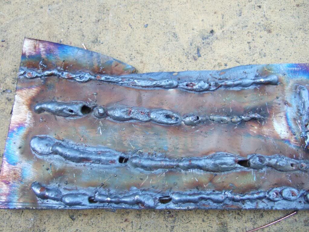
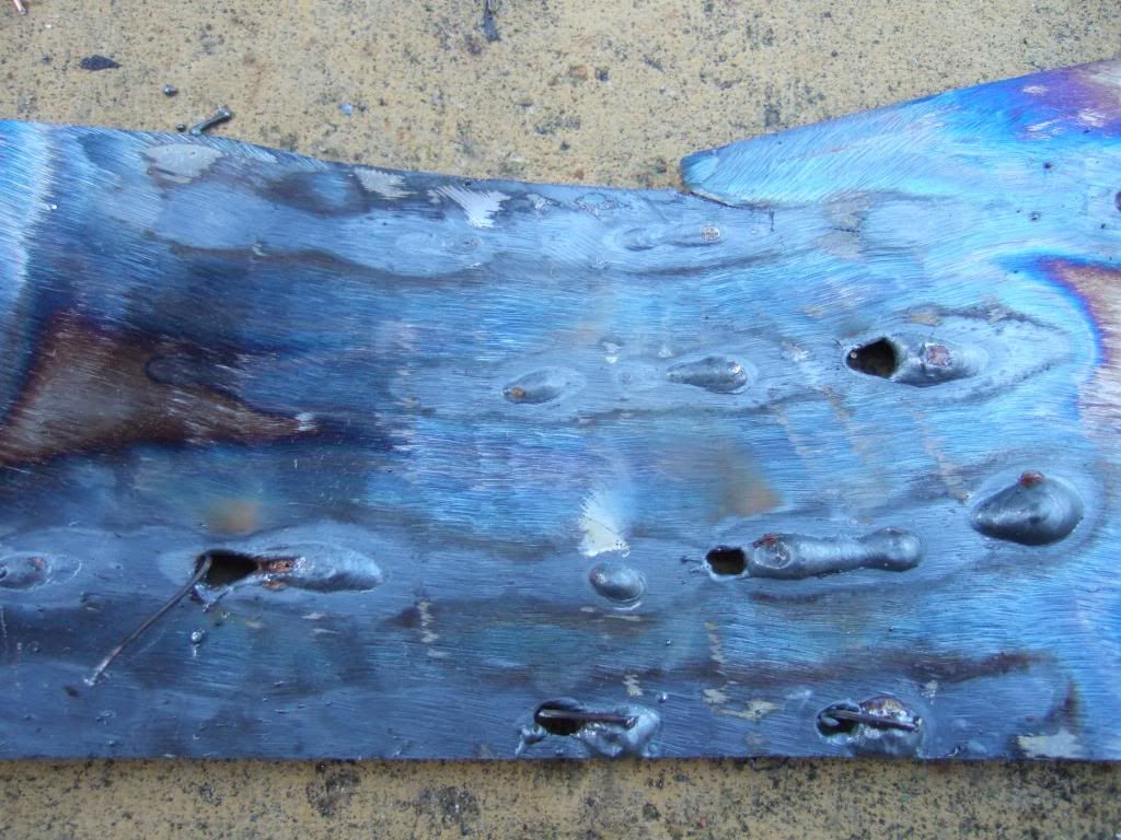
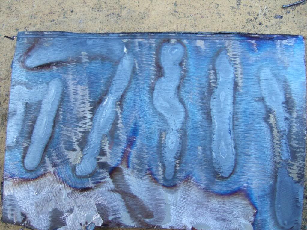
If I understand it correctly, there should be evidence of the weld on the other side of the metal.
I did play with the distance I held the torch from the metal so see what difference that made too.
( I'm sure my best welds yesterday came from working close to two edges I'd trimmed into a "V". )

This first series of welds either gave me penetration closely followed by burning straight through.
( I'm sure the speed I move the torch has a lot to do with this as I can't judge the pace yet. )

Top Side:


Flip Side:


When I tried this again on another piece, I only had the faintest traces of penetration in places.

Again this is the flip side...


I did practise on some more sections of box section, but it turned out a complete mess.
Despite my new welding helmet & having two hands to guide the welder I'm still all over the place.
Missing the joint completely is seriously driving me mad! :icon_evil:

Still, as Nike55 said above I am learning a new skill, this will take time & I should not lose heart.

Until next time, take care, Paul. :)
17 Feb 2013, 6:32pm
Paul,
Couple of ideas, check your earth clamp is clamping well, I leave just had a quick look and there are a few not so bad mig tutorials on YouTube that may be worth a look at? Books are fine but as you have discovered its difficult to learn technique from a book, at least with a video you are watching someone do it.
Getting a bit pumped about my build again now after the false start, aim is to have the finished rolling chassis at rubble in about 2 weeks as they are going to use it for development of the new frame design.
17 Feb 2013, 11:56pm
Hi Paul, with your light plinths, a visit to the supermarket with a tape measure may yield a lid from a jar of the right size that can be used as a plug for a mould. There are so many shapes within everyday items that can be utilised for moulding grp. They are perfectly shaped, just need to be trimmed to the right angle! Just a thought. N
18 Feb 2013, 8:45am
Could you not just cut a circular hole in the place you want it and pass a tube through it?
18 Feb 2013, 9:28am
garyh wrote:
Could you not just cut a circular hole in the place you want it and pass a tube through it?


Sounds like a job for a cut down Pringles tube...

- one of Mikmiglia's many useful tips.
18 Feb 2013, 10:54am
Round lights just sound a bit too easy to me. Oval rear lights is the way forwards. Erm, backwards? :)
18 Feb 2013, 8:55pm
Viatron - I did notice the wire to the welder's earth clip was a bit frayed, so I'll fix that before I try again.
I'll look at YouTube when I fix the technical problems preventing me from watching videos on my computer. :frusty:

Its great news that your frame is effectively being custom fit at source, that should remove lot of problems. :cool:

SeaNick - I might still go down the mould route just to get some practise working with fibre glass.
Although if I start seeing any more useful car shapes in everyday objects I might end up acting like this…


At which point my wife will either take the kids & run, or throw me out of the house! :icon_wink:

GaryH - If I just drilled a hole, the indicator would point down like this...


Nike 55 - I did make a note of the the Pringle tube tip.

Mister Towed - Oval rear like are like flares...
I'm sure they will come back into fashion one of these days! :icon_twisted:

- - - - - - - - - - - - - - - - - - - - - -

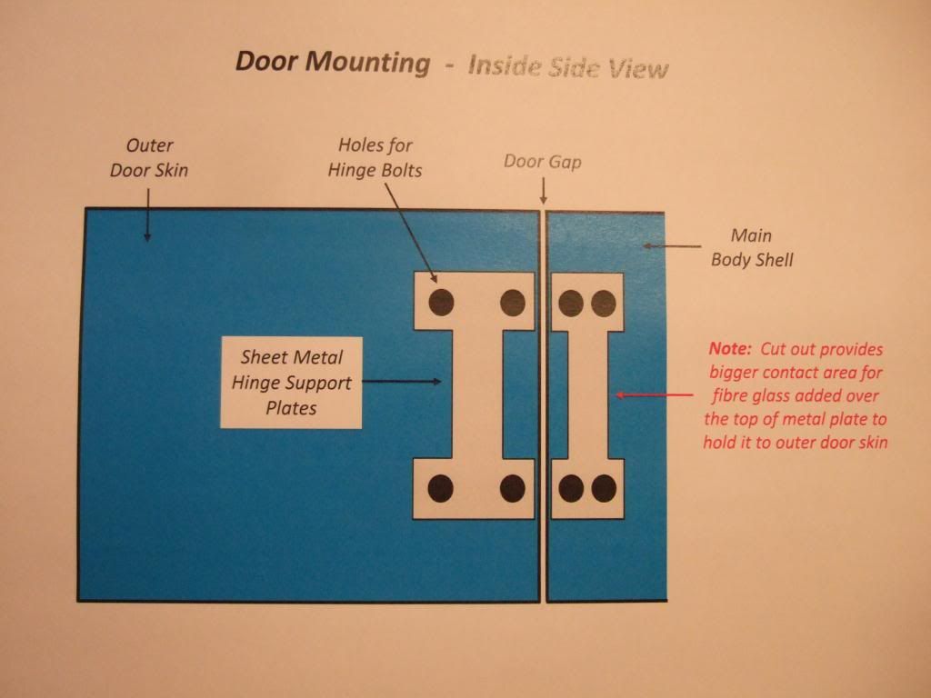
Doors - Hinge Support:
I saw this photo posted "Next Door" on the A352 thread showing the Tribute approach to door hinges…


Whilst I have no hope of constructing something similar, I have had a re-think on supporting my own hinges.
Initially, I was planning to fibre glass some metal plates behind the door & body shell for added strength.

I now plan to extend this basic idea into a single sheet of metal connecting both the top & bottom hinges.
As usual, no "scale" was harmed during the making of this sketch. :rolleyes:


I want a "thinner" middle section in the sheet metal to give a bigger surface area either side of it.
I hope that will ensure the fibre glass I add over the top to "stick" it to the outer door skin will do its job. :pray:

Well I think that is about as much effort as I can put into the theory behind fitting my doors.
So hopefully in the next few weeks I will take a deep breath and actually start work on fitting them!

Cheers, Paul. :)
19 Feb 2013, 8:42am
You can angle tube how you want it... Keep it simple.
19 Feb 2013, 8:54am
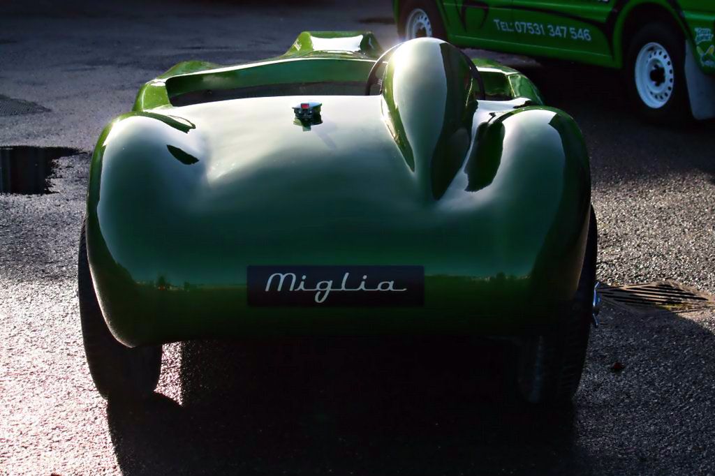
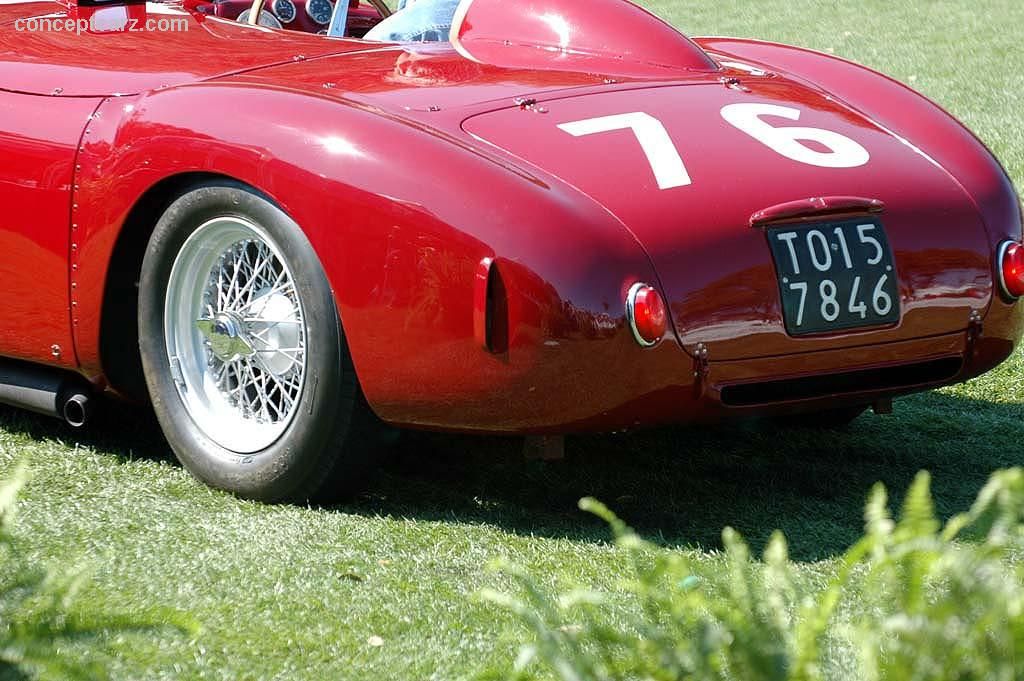
Oval lights like Lionels?

Well, they were good enough for the Mille Miglia winning original -

19 Feb 2013, 10:22am
ooh that's a pretty rear end.
19 Feb 2013, 3:20pm
Yes, it's your actual Lancia D24. :hail:
19 Feb 2013, 9:49pm
Hummmmm side exit exhausts are really pretty! I'd just be paranoid about setting the bodywork on fire :)