This is a read-only archive of the old Madabout Kitcars forum. New posts and replies are no longer possible, but every thread is still here to browse and read.
Today i cleared the garage out as it was starting to get a little untidy with gear all over the place so no progress on the body.
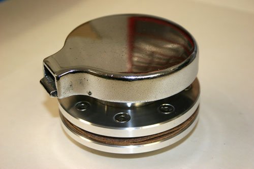
Did some more manual turning of a petrol cap mount, i wanted to keep the original flip cap but add a little extra to the cap mounting, will have to replace the rubber seal as it's perished.
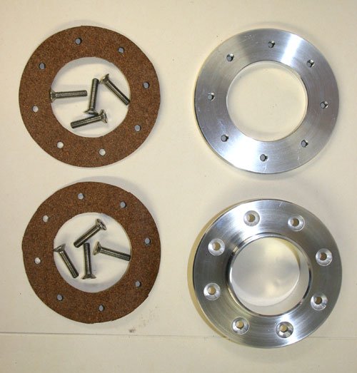
Machined the mount tube and clamp ring out of ally bar with 8 counter sunk holes and the clamp ring has 8 tapped holes, cut two cork gaskets 1.5mm thick.
Attachment “IMG_4826.jpg” from the original forum could not be reliably recovered.
The second image has the original spitfire flip cap fitted, its had a quick polish on the wheel to bring out the chrome while leaving the marks for a patina look.
Tomorrow i hope to have some progress with the bonding of the body to the sub frame all been well.
Paul Never gave that a thought I'm just adding bits and piece that i think will look good, however i am trying to replicate a 50's sports car as far as possible with the interior finish, may be somebody can suggest a brand of car that the car may replicate with the bits i have added so far.
Paul Thanks for the very comprehensive lesson in all things 50's style race cars there's some great looking cars. I have a good idea of the marque i would like but at the end of the day i think the cars style will attract the attention rather than which marque it is.
Viatron I've already bought the paint and i can tell you it's not blue.
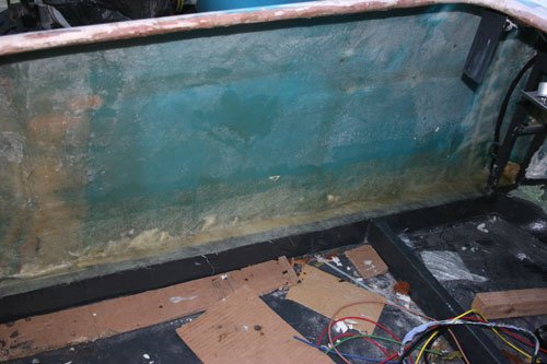
After looking at the best way to tackle the outer sill area i've decided to make a fiberglass trim to extend the body sides down in line with the sub frame box section and to give a straight as possible bottom sill.
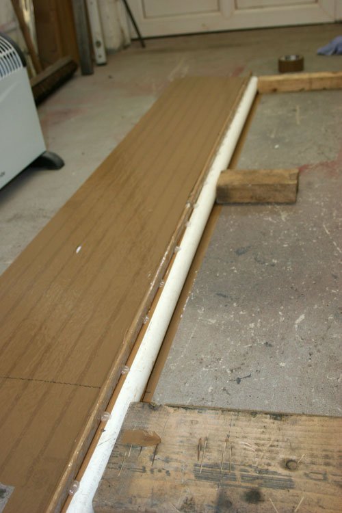
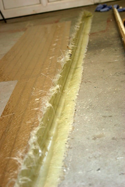
I had a length of 40mm plastic pipe and oval conduit which i've used to make a mold from.
The plastic pipe was covered in brown packing tape then the oval conduit was hot melt glued into position with brown tape applied to prevent the fiber glass from sticking.
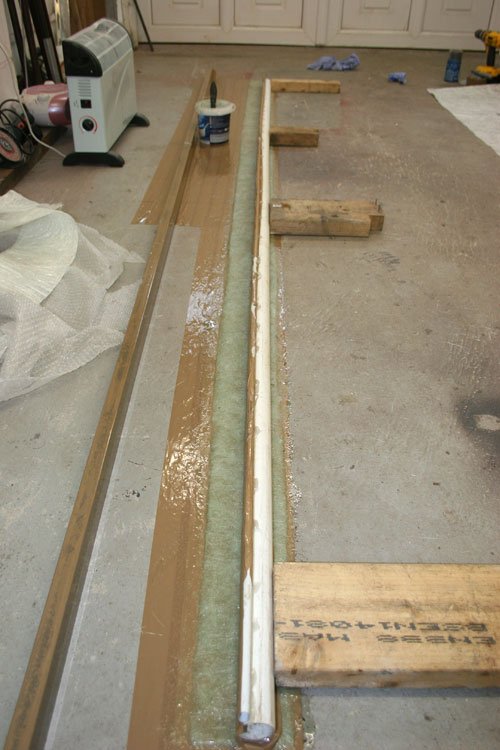
Used four layers of fiber glass laid out on to brown packing tape then positioned the mold.
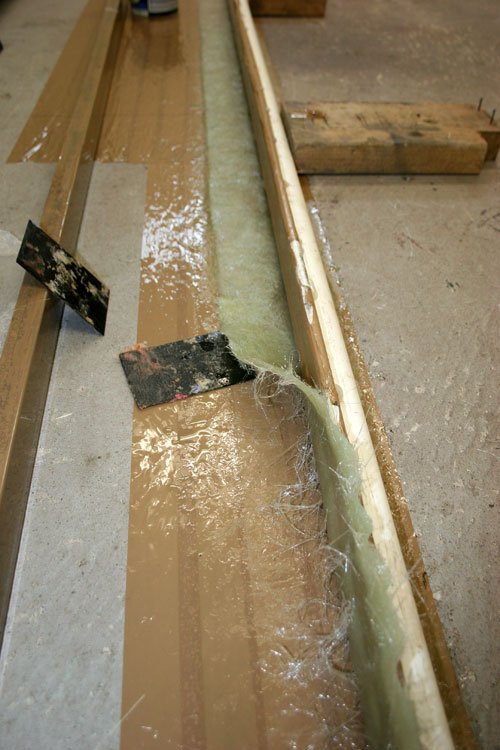
Used two filler scrapers to lift the wet fiber glass up along the side.
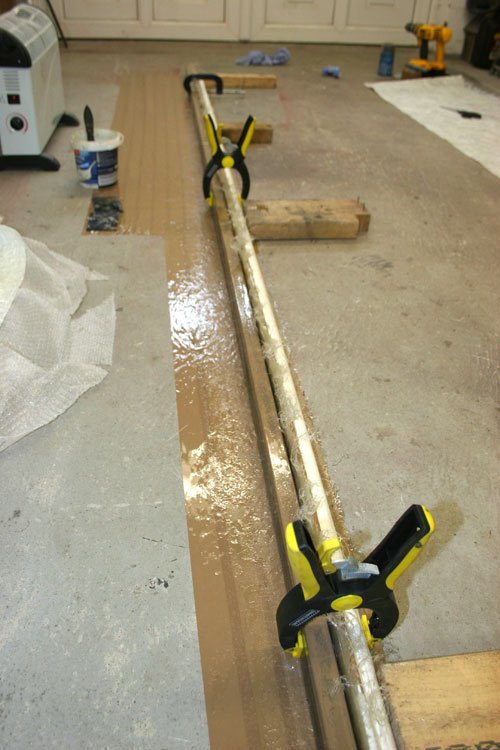
Clamped a length of rectangular section up to the mold for good measure.
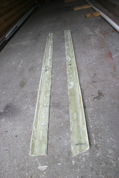
The finished trim which will be trimmed to size to suit each sill area. My intentions are to rivet into the sub frame rectangular box section a length of 40mm x 3mm ally plate along the full sill length on top of the fiber glass to create a sandwich effect for added strength. I'll also glass the trim on to the out side of the body and a run of bonding paste between the inside of the body and the sub frame rectangular section, then back fill the interior sill void with expanding foam not forgetting to place the round plastic conduit into the sill void before applying the foam.
Once the foam has cured ill glass over the top to tie in the shell and sub frame for extra security, the fiber glass will be hidden by the ally floor sections i intend to fabricate and fit. So hopefully this will be strong enough to last.
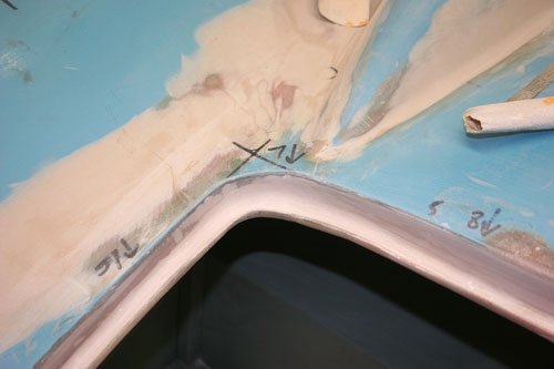
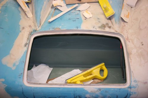
Started to finish the rear boot rain channel today with fiber filler and then body filler.
Attachment could not be found in the archived database.
First i back filled the gap with fiber filler that was left from the foam mold i used originally to create a rain channel (second image shows this gap), this has added strength to the whole boot aperture, then finally filling in all the small holes and uneven surface with body filler.
Just the rubber seal to fit over the inner edge along with two drain tubes in each lower corner to drain the rain water away.
Attachment could not be found in the archived database.
A before and after photo.
Tomorrow i will finally start to bond the body to the sub frame as well as fit the lower side sills to finish off the lower body wonky lines.
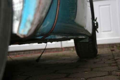
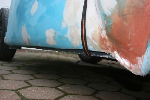
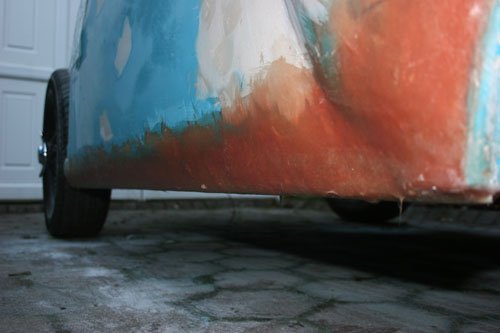
This shows the drivers side lower sill which dips at the front and back edges so hopefully the trim i made last weekend will be easy to bond and blend in, will take plenty of photos to post on the forum.
Paul Its easier to see what i mean with photos so hopefully the next installment of the sill work will help.
The sill trims cut down to size before bonding to the car.
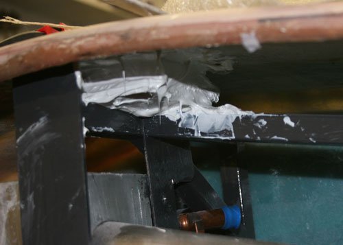
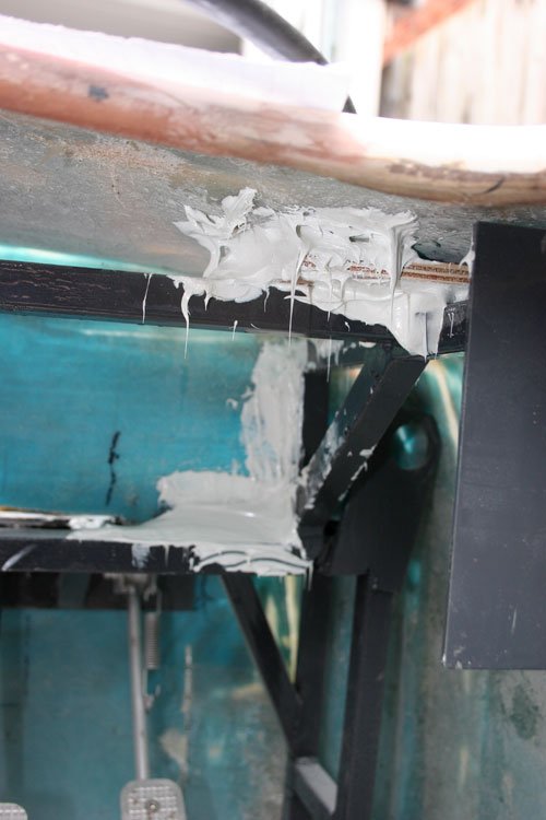
I've bonded the shell to the sub frame at various points where the frame was very close to the body, simply bridged the gap with bonding paste and ply pads, it looks messy but does the job, tomorrow ill glass over for added security. The area in between the two humps has a metal pad welded to the sub frame with a gap between the body which i filled with paste, its made a big difference to the rear body strength, thanks for the tip Mr T.
I've also bonded the sill trims to the body but unfortunately i have no photos so will take some tomorrow. :[
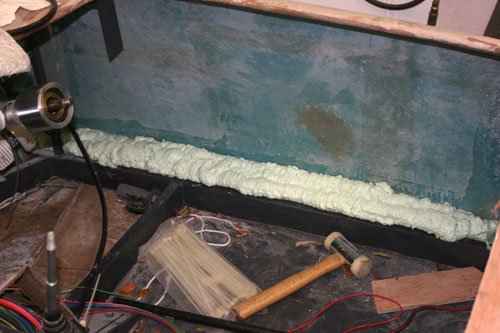
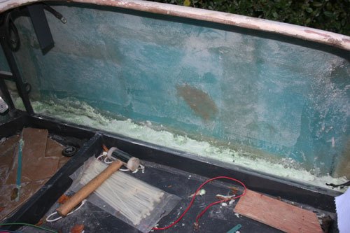
In the inner sill void i back filled with a little bonding paste along where the body meets the rectangular section of the floor frame then placed the plastic conduit into the space and finally filled with expanding foam which i will trim flush tomorrow before glassing over.
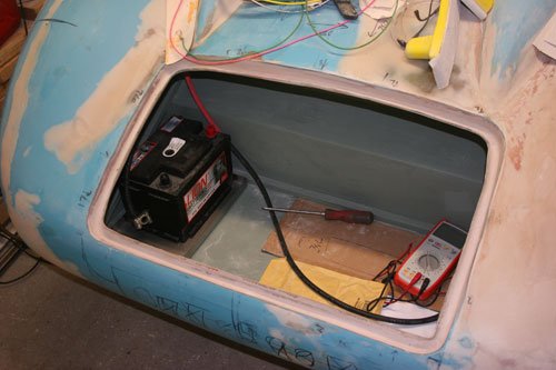
Made a battery tray out of stainless steel tig welded the corners then fitted it to the boot space to add some of the weight to the rear of the car, just need to fit the battery clamps now. Welded in a few earth studs to the rear and front areas of the frame which i will use as earthing points for the electrical components.
It's been a good day today first Lewis Hamilton is world F1 champion and i finally have the body bonded to the sub frame.
A before and after photo of the passenger sill area, i glassed over the sill trim to bond into the body then applied a coat of fiber filler to fill in any undulation, so just to rough smooth with 80 grit then apply body filler to hopefully blend in. The fiber glass sill trim i made was bonded to the body first then glassed over the top and finally fiber filler added.
Trimmed back the expanding foam level with the rectangular sub frame and glassed over which tie's in the sub frame to the body side, its surprising how strong this has made the body sides so all in all i am very pleased with the result. You won't be able to see any of this once the side ally panels and floor panels have been fitted.
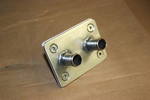
While the glass fiber was going off which has taken a long time today due to the cold temperature i decided to make a stainless manifold for the heater pipes, this will be mounted in the bulk head to transfer the water pipes from the engine to the heater through the fiber glass bulk head.
Its made from 3mm stainless plate with 16mm o/d stainless pipe machined down to 15mm o/d to grip the rubber pipe, I've also made a back clamp plate from 3mm ally plate to sandwich the fiber glass for strength.
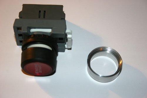
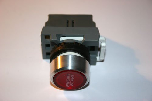
Made another small part from the never ending list.
Its an ally screw ring for the start button, the original was naf black plastic so to keep in with the rest of the interior parts i decided it should be ally. Threaded with a couple of chamfers etc.
Just about finished the boot lid yesterday only have the latch mechanism to make.
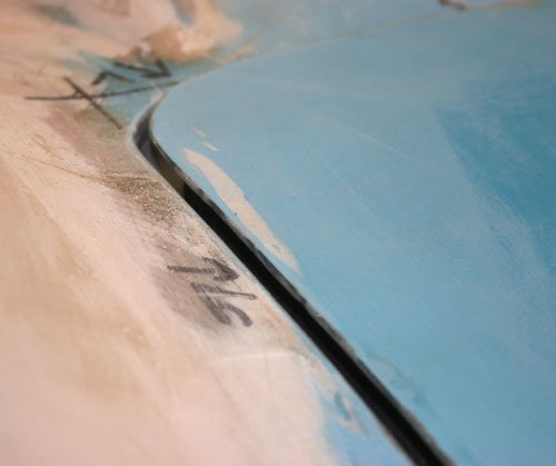
I've added this picture for Paul to see how high my boot lid sits under its own weight on the rubber lip seal, the locking mechanism will pull the lid level with the body when closed.
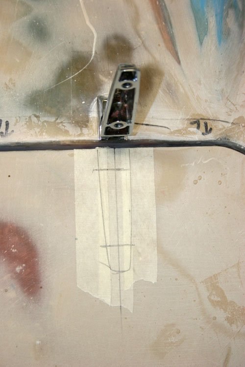
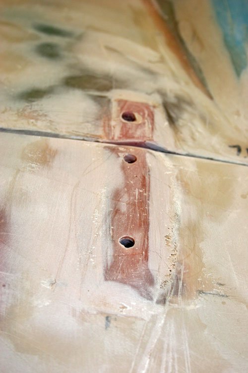
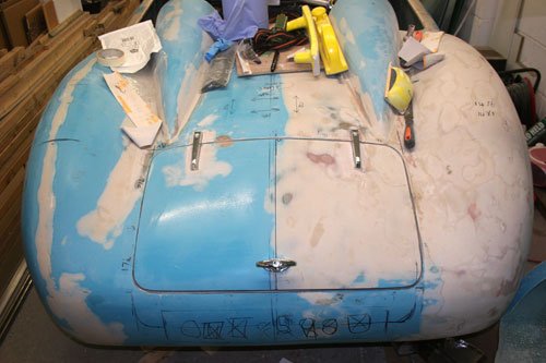
First i marked out the position for the hinges making sure they were central and equally spaced to the boot aperture etc. The body surface were each hinge mount's onto has to be built up slightly to give a level surface so that the hinges don't try to twist against each other when opening the boot lid, i used a little fiber filler then filed flat before marking and drilling the holes, also used a little body filler.
This photo shows the flat surface built up with fiber filler.
Once both hinges were fitted and working correctly i drilled a couple of holes for the lock.
The boot lid is just about complete only the latch mechanism to make hopefully sometime this week.
I've now started to look at the pedal box fitted from the original spitfire and so far can see that the pedal lengths require shortening by about 40mm as i have fitted the floor below the pedals level with the top of the sub frame so the next job is to remove and cut then weld back together.
I did consider fitting a floor mounted pedal box but the 14 inch wheels I've fitted would hit the master cylinder's so i decided to keep the original spitfire pedals with some alterations.
Well that's it for now see you all soon and i will post pictures of the pedal mods.
Cheers Mac, without the flat mounting surface they would, i did consider fitting internal hinge loops but after thinking about it external hinges were easier to fit etc plus the chrome will look good against the paint.
I know it's not much use to you now but it might help some one else.
Morris Minor bonnet hinges are set to allow for the curve of it's bonnet and to my eye that curve is about the same as the Navigator's boot lid .
That's looking good and it's also highlighted to me that I've "got away with it" as far as using Mini door hinges on my bonnet as the curve is just right without having to build things up.
Micky1mo Thanks for the tip on the minor hinges, i did look at them but i thought they were slightly longer than the hinges i have so the down ward curve of the boot would have to be adjusted to suit the flat surface of the minor hinge, i may have this wrong and somebody may correct me, thanks any way.
Davecymru Thanks, its sometimes good to post things on here as it helps others in the long run.
Paul Thanks and i must say your boot lid looks the part with the split humps, i did originally look at doing something similar but in the end decided on the easier route plus the Navigator has the shorter humps so the boot would of ended up rather large.
Made a little progress today however its a little bit too cold in the garage at the moment to be working outside so i decide to make a catch for the boot lid out of ally.
Attachment “IMG_4882.jpg” from the original forum could not be reliably recovered.
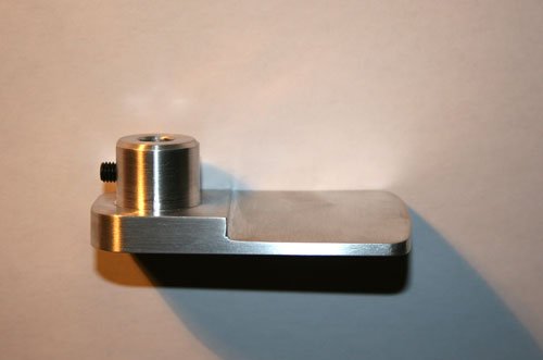
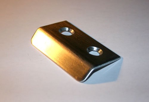
Machined from a solid piece of ally with a lead in edge of about 8 degrees. Rough dimensions are 80mm x 30mm x 18mm.
The striker plate i hope will be fastened to the thick edge i have made around the boot aperture for the rain channel with two 6mm countersink's and a little bonding paste.
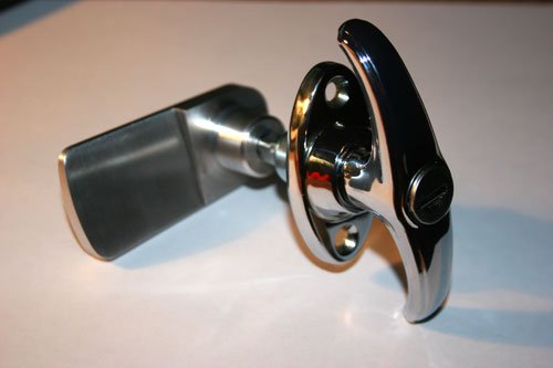
Catch fitted to the chrome handle, it will be positioned and held in place with a 5mm grub screw and a little thread lock for good measure.
Well that's it for now and hopefully i will have made some more progress this weekend but as the weather turns colder it is becoming more of a draw to stay in doors.





 .
.