MadaboutKitcars

This is a read-only archive of the old Madabout Kitcars forum. New posts and replies are no longer possible, but every thread is still here to browse and read.

Royale Sabre - Take two!

16 Oct 2016, 6:59pm
peterux wrote:
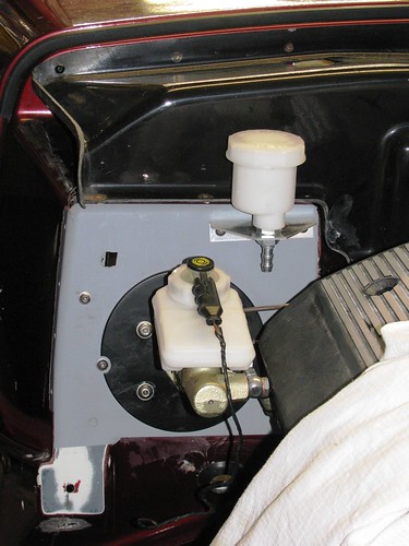
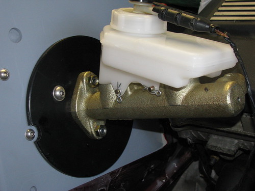
Brake Master Cylinder mounting by marlinpeter, on Flickr

Whilst the brake master cylinder clears the engine OK, one of the ports is directly opposite the rocker cover. Even with the tightest bend, the pipe still wouldn't fit even if I carved a slot in the cover. The solution I came up with is to use a banjo fitting.
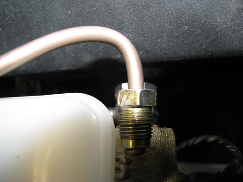
Brake M/C to Servo lines by marlinpeter, on Flickr

Having decided to use a banjo fitting but I found the price of separate fittings so high that I decided to go for some complete custom flexible lines from HEL. The banjo fitting fitted just fine but an unforeseen issue is that the other end doesn't fit my Iruna brake servo slave cylinder.

Brake M/C to Servo lines by marlinpeter, on Flickr

Despite remembering to order 3/8" UNF to match the Iruna servo the HEL fitting doesn't tighten before the threads bind at the bottom of the hole. I think the issue is that the HEL fitting is threaded right to the end whereas some fittings have an unthreaded section just before the flared end of the pipe.

Brake M/C to Servo lines by marlinpeter, on Flickr

To solve this issue I've made up this short adapter but its not a very eloquent solution and not very mechanically strong. (By now I was wishing I bought separate fittings and ran the lines in Knufer pipe.)

Brake M/C to Servo lines by marlinpeter, on Flickr

The other idea I've had is to try and carefully file away the last two threads but I'm not sure I can do this without damaging the fitting.

Any other suggestions welcome!

cheers, Peter


I think as a first thing to try I would ask HEL what they suggest. You never know they might remake with a different fitting for free! It would be good PR for them :-)

Cheers Robin
16 Oct 2016, 9:33pm
MartinClan wrote:
I think as a first thing to try I would ask HEL what they suggest. You never know they might remake with a different fitting for free! It would be good PR for them :-)

Cheers Robin
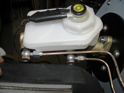

Robin,
yes, I've taken this photo today to better explain the issue. I've now emailed it to HEL to seek their advice.
Brake line fitting issue by marlinpeter, on Flickr
John,
your three way bulkhead suggestion would certainly work but maybe it would look a little messy as there are two lines.

thanks, Peter
3 Nov 2016, 8:33pm
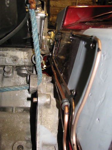
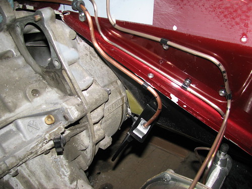
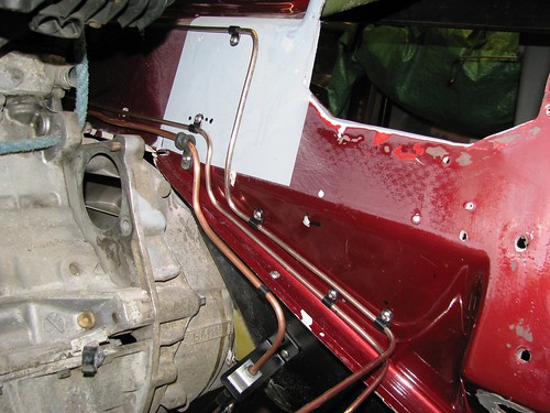
Well sorry to say this but HEL custom hoses were as useful as a chocolate teapot so I've resorted back to the tried and tested Copper/Nickel brake pipes.
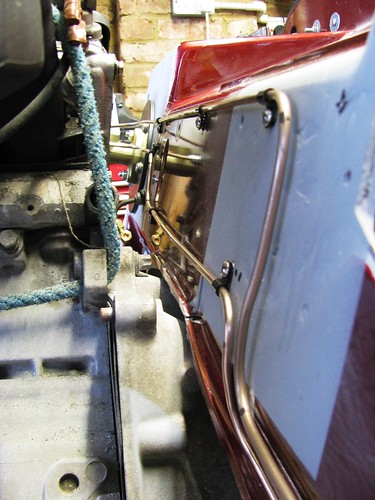
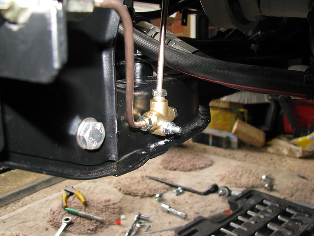
These Goodridge banjo fittings solve the problem of clearance with the ignition coil cover.

Brake pipes - M/C to Servo by marlinpeter, on Flickr

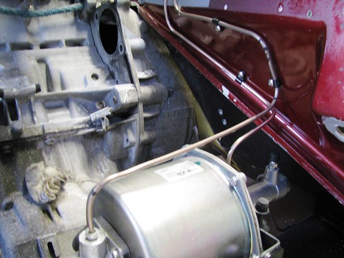
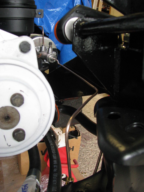
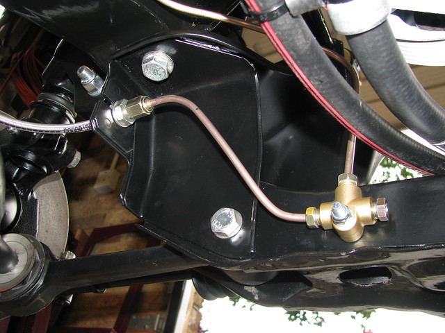
Brake line routes chosen to work around the heater hoses.

Brake pipes - M/C to Servo by marlinpeter, on Flickr

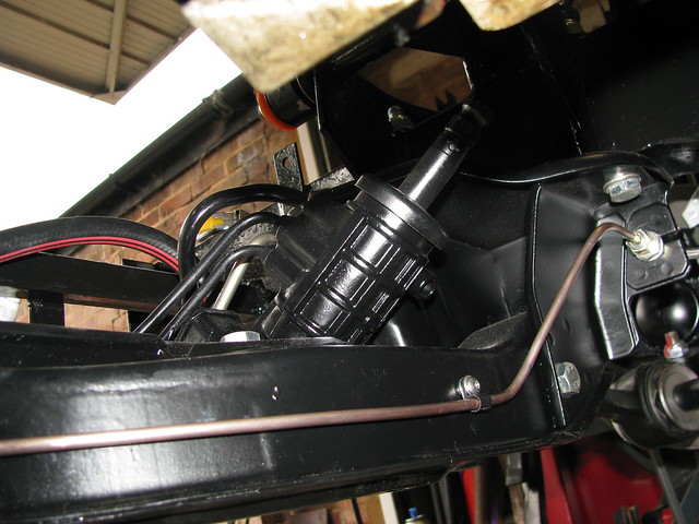
And then down to the remote servo.

Brake pipes - M/C to Servo by marlinpeter, on Flickr

Also, way ahead of my needs but a bit of what I call 'armchair building' resulted in this nice VIN plate. It's engraved lettering on brushed stainless steel. I just hope DVSA don't change the requirements before I'm ready for my IVA!!
VIN Plate by marlinpeter, on Flickr

Next up will be the clutch hydraulic line from M/C to slave cylinder.


...peter
3 Nov 2016, 8:59pm
Well it may have been some hassle and involved some avoidable expense but in the end the solution you have come up with works well and to my eye looks better than the original Hel approach, copper / nickel sort of looks right on the Sabre.

John
5 Nov 2016, 8:12pm
cabrioman wrote:
Well it may have been some hassle and involved some avoidable expense but in the end the solution you have come up with works well and to my eye looks better than the original Hel approach, copper / nickel sort of looks right on the Sabre.

John


Thanks John, with hindsight, I think you are so right. From now on,I'll be sticking to traditional parts where possible.
5 Nov 2016, 8:30pm
I've now completed the clutch hydraulic line from the clutch master cylinder to the slave cylinder.

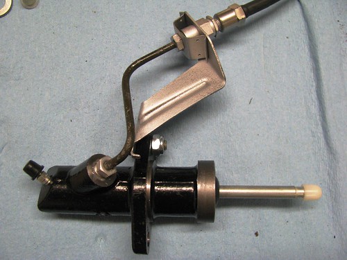
I've used a new Febi clutch slave cylinder and a HEL flexi hose. The short fixed pipe and bracket are from the BMW donor.

Clutch Slave cylinder by marlinpeter, on Flickr

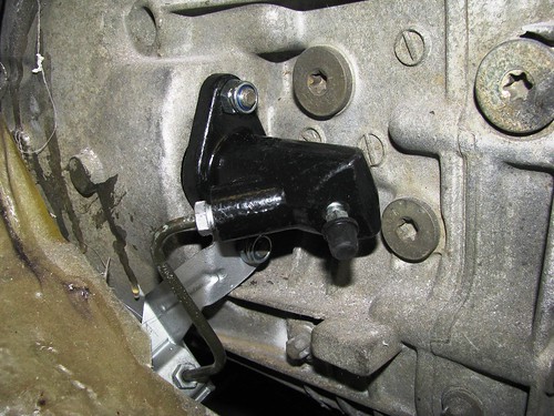
Clutch Slave cylinder fitted. I need BMW locknuts as the studs are quite short.

Clutch Slave cylinder by marlinpeter, on Flickr

Clutch hydraulic line made up from 6mm microbore copper pipe.

Clutch M/C to slave line by marlinpeter, on Flickr

Clutch line routed to bracket fixed to body tub.

Clutch M/C to slave line by marlinpeter, on Flickr

But I wasn't happy with the routing of the front brake line so I have remade it.

Brake M/C to servo - v2 by marlinpeter, on Flickr

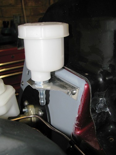
Clutch hydraulic reservoir mounted. The ali bracket came with the reservoir but it's a bit flimsy so I will probably remake from steel.

Clutch Reservoir by marlinpeter, on Flickr

I will drill the hole for the fluid hose the next time the engine is removed.

Clutch Reservoir by marlinpeter, on Flickr

Well that will be all for now, for a couple of weeks whilst I catch up on some other projects....

....peter
30 Nov 2016, 8:25pm
Front brake caliper refurb

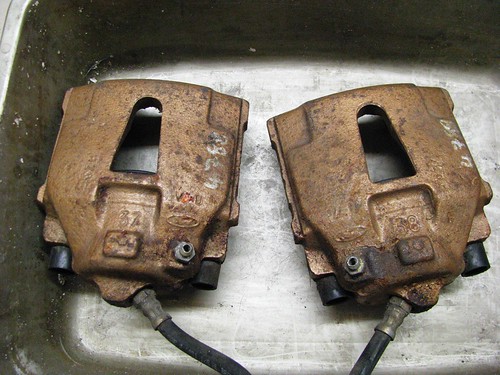
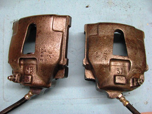
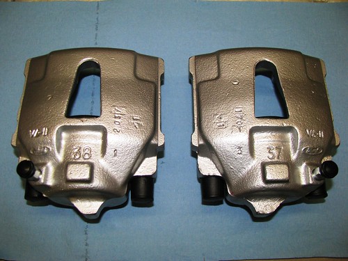
These are the brake calipers that came with the Sabre. They show signs of being refurbished before but don't show any signs of any major rust pits, so I've decided to refurbish them myself. The brown colour is a mixture of gold paint and surface rust.

Front bake caliper refurb by Sabrebuilder, on Flickr

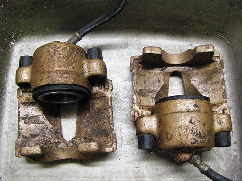
Front bake caliper refurb by Sabrebuilder, on Flickr

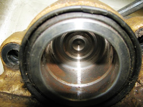
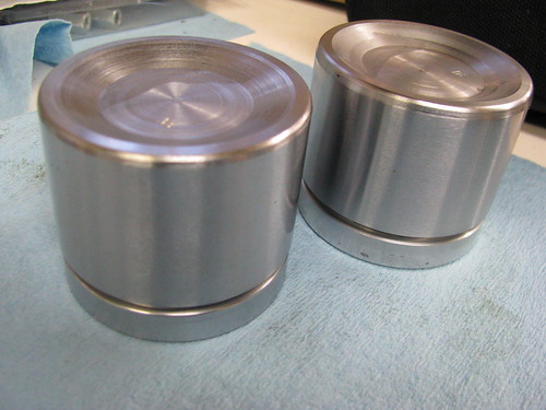
The brake caliper pistons look like new items when the calipers were refurbished back in 1995. All rubber seals will be replaced but the pistons look re-usable.

Front bake caliper refurb by Sabrebuilder, on Flickr

These are calipers after paint stripping, derusting and wire brushing. They have been oiled with 3in1 oil to stop them rusting again before I paint them. At this stage I've left the pistons, bleed niplles and the old hoses in place to stop dirt getting inside the calipers chambers.

Front bake caliper refurb by Sabrebuilder, on Flickr
(the strange brown colour is a trick of the camera and flourescent lights)

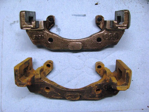
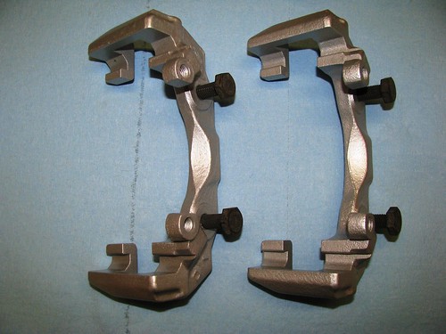
Caliper carriers. The top one has been cleaned up. The remaining black paint wouldn't shift with the paint stripper so I had to use wire brushes in a drill.

Front bake caliper refurb by Sabrebuilder, on Flickr

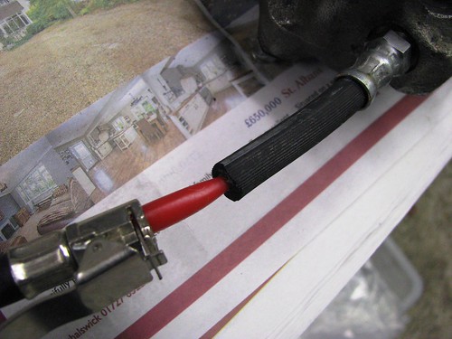
I saw this tip on the internet and it worked a treat! It's a car air pump inflatable adapter which you just push into the cut off old flexi hose. A little compressed air and the cylinder just pops out with no effort.

Front Brake Caliper rebuild by Sabrebuilder, on Flickr

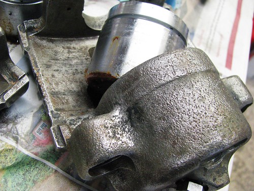
Piston popped out without any issues.

Front Brake Caliper rebuild by Sabrebuilder, on Flickr

The caliper pistons came up looking like new after a quick clean up with very fine wire wool and oil.

Front Brake Caliper rebuild by Sabrebuilder, on Flickr

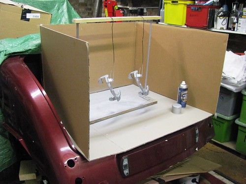
The Sabre's boot makes good temporary spray booth.

Front Brake Caliper rebuild by Sabrebuilder, on Flickr

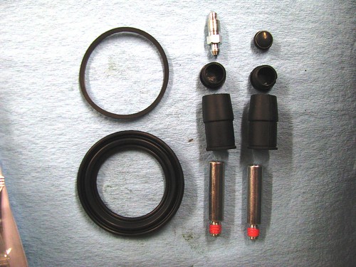
Brake caliper rebuild kits purchased from Brakes International.

Front Brake Caliper rebuild by Sabrebuilder, on Flickr

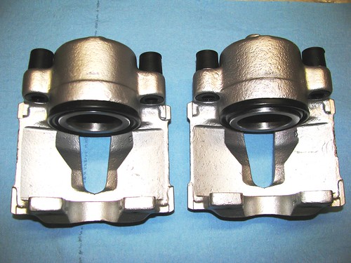
After finishing painting and leaving for a few days for the paint to harden, i fitted the new seals and rubber parts. The service kits came with assembly grease and all parts fitted perfectly.

Front Brake Calipers by Sabrebuilder, on Flickr

And finally, the brake caliper carriers painted and new 10.9 bolts ready for fitting.

Front Brake caliper carriers by Sabrebuilder, on Flickr

There now all wrapped up in a shoe box ready for fitting.... Quite a lot of messy work and time but much more satisfying than buying refurb'd calipers.

...peter
30 Nov 2016, 8:56pm
Looking good!
1 Dec 2016, 7:24am
Job well done, as no one could do it better than yours elf.
1 Dec 2016, 6:47pm
Amir Manzoori wrote:
Job well done, as no one could do it better than yours elf.


It would be nice to have a few elves in my garage....they could finish my car for me for Christmas!! :badgrin:
1 Dec 2016, 7:05pm
Misspelling

Sorry for the misspelling. The sentence should have ended with YOUR SELF and not yous elf
1 Dec 2016, 10:59pm
peterux wrote:
It would be nice to have a few elves in my garage....they could finish my car for me for Christmas!! :badgrin:


......... and spoil all your fun?!
No, let the elves help Santa and leave you to do what you do best
:eusa_angel:
13 Dec 2016, 9:40pm
Propshaft tunnel mods

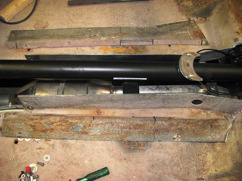
I've been putting off completing the gearbox cover so decided it was best to complete the mods on the propshaft tunnel first.
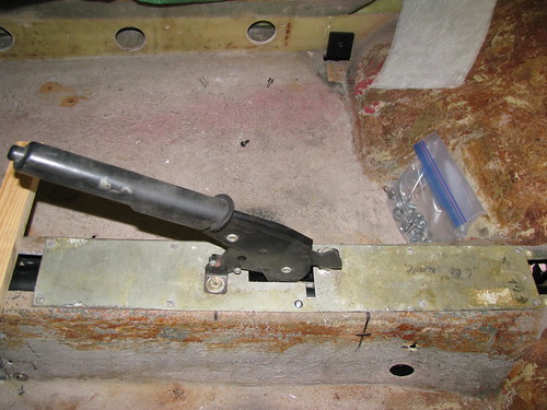
The Sabre is designed to use the Ford Sierra handbrake and cable. This is mounted to a steel plate mounted above the propshaft tunnel.
Since the BMW engine and gearbox are mounted higher up to clear the front chassis crossmember the propshaft runs higher in the tunnel and now fouls on the handbrake mechanism.

Handbrake by Sabrebuilder, on Flickr

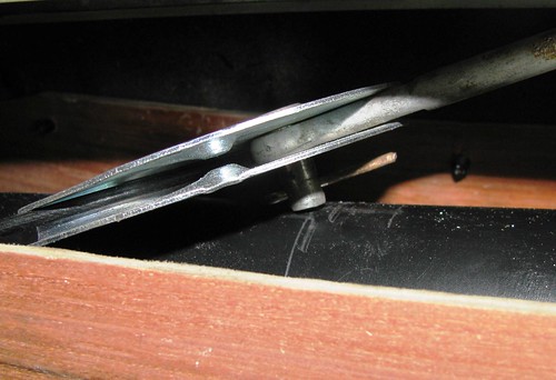
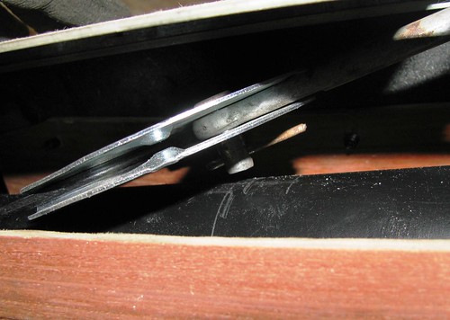
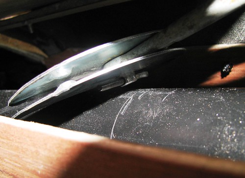
Here you can see where the handbrake clevis pin fouls on the propshaft.

Handbrake Tunnel Mods by Sabrebuilder, on Flickr

I tried raising the handbrake by putting 20mm square section ali tube between the tunnel top and the handbrake mounting plate but the handbrake cable half moon bracket fouled on the top of the tunnel. So I decided to cut the top of the propshaft tunnel of with a slitting disc in my angle grinder to allow me to raise it by 20mm.

Handbrake Tunnel Mods by Sabrebuilder, on Flickr

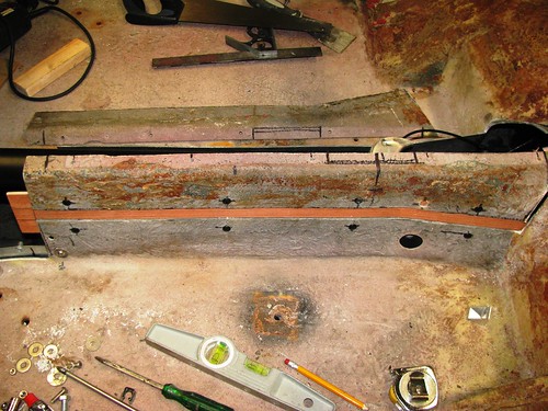
I then prepared two strips of 3mm plywood to temporarily hold the tunnel tops raised by 20mm. Here is the plywood strip fixed with self tappers on the passenger side.

Handbrake Tunnel Mods by Sabrebuilder, on Flickr

With the passenger side tunnel top fixed and the handbrake refitted I could now see the problem better from the drivers side. Despite raising the top of the tunnel by 20mm, the clevis pin was still resting on the propshaft.

Handbrake Tunnel Mods by Sabrebuilder, on Flickr

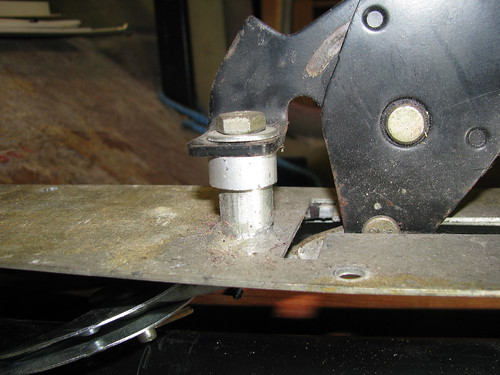
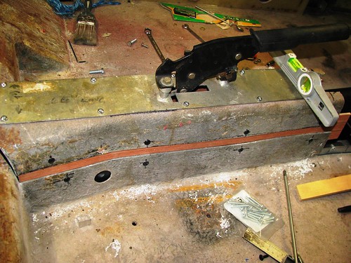
I didn't want to raise the tunnel anymore but realised I could raise the handbrake on its mounting plate without the puller rod fouling on the plate, so I cut and fitted two 10mm spacers.

Handbrake Tunnel Mods by Sabrebuilder, on Flickr

With the tunnel raised and the spacers fitted the clevis pin was just clearing the propshaft but still a bit close. The clevis pin is not a standard Ford part and was fitted by the original builder.

Handbrake Tunnel Mods by Sabrebuilder, on Flickr

I cut the clevis pin down and re-drilled another hole making it a better fit. I plan to replace the old split pin with an 'R' clip or maybe try to source an original Ford pin with a circlip. This picture shows the clearance with the handbrake in the off position. It's even better with the handbrake pulled on.

Handbrake Tunnel Mods by Sabrebuilder, on Flickr

Here's the handbrake and tunnel fixed with the plywood former on the drivers side.

Handbrake Tunnel Mods by Sabrebuilder, on Flickr

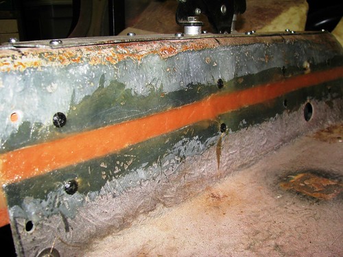
I then dismantled it all and cleaned up the surfaces of the tunnel with a flap wheel in the angle grinder. Then re-assembled with brown packing tape applied to the plywood to stop the fibreglass sticking to the plywood formers.

I've filled the gaps with P40 GRP filler. I will then overlay both sides with a few layers of GRP to restore the original strength of the tunnel.

Handbrake Tunnel Mods by Sabrebuilder, on Flickr

When the the tunnel is finished and in its final position I can then move on and tackle the gearbox cover.


...peter
26 Jan 2017, 10:26am
Well with Christmas and New Year celebrations over and all the decs put away it was time to get back in the garage before spring arrives and other outdoor projects become a priority again.
It's been b***dy cold in this part of the country and my garage is old detached and often colder inside than outside.
I thought I would tackle the wiring of the dashboard thinking that would be something I could do indoors but all the preparation work has been outside in the cold....

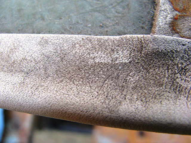
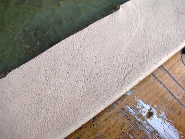
The Sabre I bought had the dashboard surround covered in cream coloured leather by a professional upholsterer in about 1995. The leather covering was very dirty after 22 years of neglect! My original plan was to rip it off and start again but I thought I'd have a go at restoring it first. I tried various cleaners but the most effective was Vanish carpet cleaner. It's come up quite well but some small scuffs will need to be treated.

Dashboard surround - before by Sabrebuilder, on Flickr

And after cleaning....

Dashboard surround - after by Sabrebuilder, on Flickr

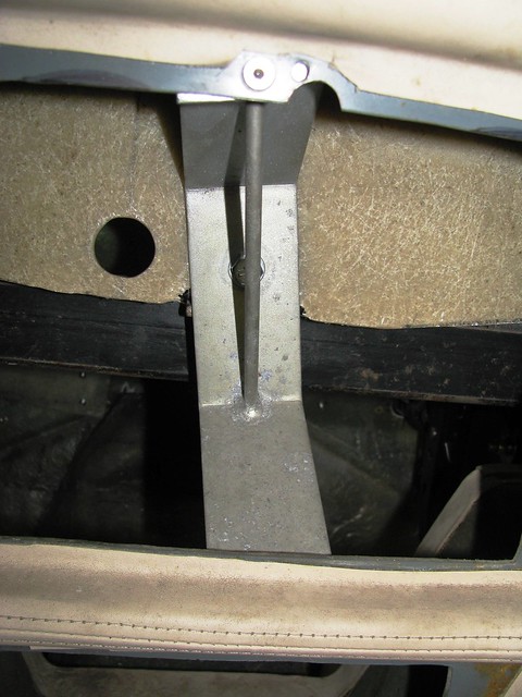
The dashboard surround is mounted by this central bracket that bolts to the scuttle frame plus a 'z shaped' bracket at each end. The central bracket clashed with one of the warning lamp holes already pre-cut in my dashboard, so I had to mount it slightly rotated.

Dashboard Surround mounting by Sabrebuilder, on Flickr

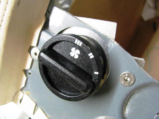
I'm using a Ford Sierra fan motor switch. I had to make a metal plate to mount the switch behind the GRP dashboard surround. These little jobs can be very time consuming!

Heater Fan Switch by Sabrebuilder, on Flickr

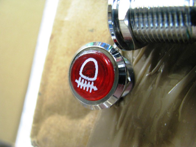
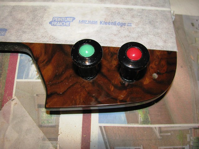
I couldn't find any warning lights that I liked so I made these out of two different lamps. The bodies are LED indicators from Hong Kong and the lens was cut of the top of a Europaspares lamp. The lens was lapped flat and then carefully bond to the body with clear silicone sealer.

LED Warning Lamps by Sabrebuilder, on Flickr

And finally for this update, Durite period looking fog light switches mounted in the 'IVA dashboard exempt zone' (hopefully!).

Front and rear fog light switch by Sabrebuilder, on Flickr

More to follow next week.....

....peter
14 Apr 2017, 7:09pm
peterux wrote:

I had already bought a pair of Mk1 MX5 seats but they don't have the shoulder high seat belt supports. My Sabre chassis has rather low seat belt mounting positions that would fail the IVA regulations. The Mk3 MX5 seats have seat belt supports that raise the turning point. I believe the IVA will accept this as a solution as long as the seats are designed to take the forces.

Mazda MX5 Mk3 seats by marlinpeter, on Flickr

....peter


Having further looked into the IVA rules for using seats with built-in seat belt supports I have decided against them. To use these seats I would need to have structurally strong base supports welded to the chassis rails. I now think it will be much easier to raise the original shoulder height supports and use the Mk 1 seats.
On the upside, I bought these seats for £50 and sold them for £155 :smile:
15 May 2017, 7:30pm
Sorry for the lack of updates but I've been busy with other projects for most of the winter and spring. The only real progress has been reconstructing the gearbox tunnel to fit around the BMW gearbox which has actually taken more time than I would have liked but I'm nearing completion now.

It's not terribly exciting so I'll mostly let the pictures tell the story....
(you can click on any of the photo's for more details :smile:)

Gear change support by Sabrebuilder, on Flickr

Gearbox Tunnel mods by Sabrebuilder, on Flickr

Gearbox Tunnel Mods by Sabrebuilder, on Flickr

Gearbox Tunnel Mods by Sabrebuilder, on Flickr

Gearbox Tunnel Mods by Sabrebuilder, on Flickr

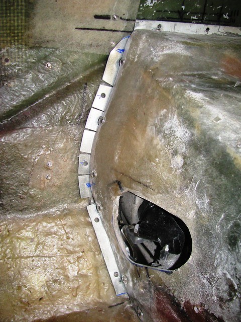
Steel flange added to left-hand side. All flanges are spaced off the bulkhead by about 3mm. The gap will be filled with Neoprene foam sealing strip.
Gearbox Tunnel Mods by Sabrebuilder, on Flickr

Gearbox Tunnel Mods by Sabrebuilder, on Flickr

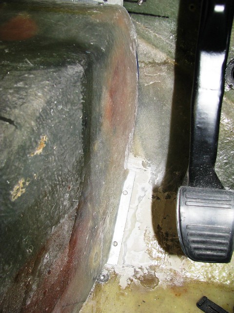
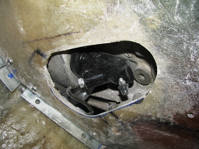
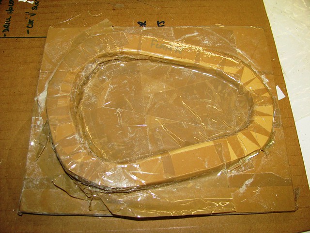
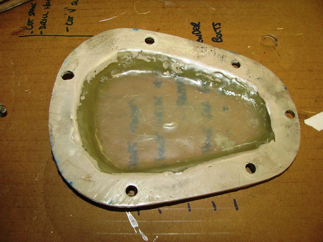
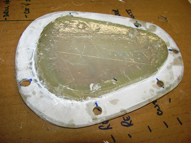
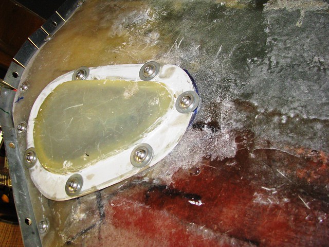
I needed to make a small access panel to go over the clutch slave cylinder which is accessed through a hole in the side of the gearbox tunnel. The clutch hydraulic pipe is slightly proud of the tunnel side so the cover needed to be raised. I made this mould out of artists foam board and packing tape. (This picture was taken after the mould had been used.)

Clutch Slave cylinder gearbox tunnel cover by Sabrebuilder, on Flickr

Clutch Slave cylinder gearbox tunnel cover by Sabrebuilder, on Flickr

Clutch Slave cylinder gearbox tunnel cover by Sabrebuilder, on Flickr

I used m6 flanged screws and nutserts (rivnuts) to fix it to the tunnel. I will probably seal around the flange with RTV silicone when the car is finished. The panel will be hidden by the carpet and underlay.

Clutch Slave cylinder gearbox tunnel cover by Sabrebuilder, on Flickr

Next update will follow when time permits....:eusa_whistle:
24 Jun 2017, 8:20pm
Time for a small update from the last few weeks....

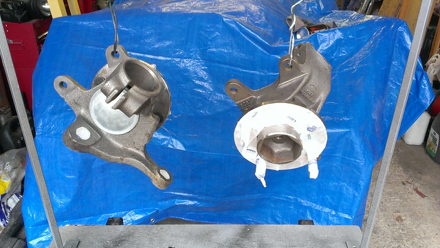
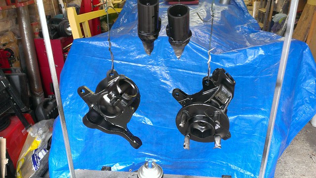
I had an issue with the original donor car's front hubs that came with my kit. They had a lot of play in the bearings and changing the bearings (twice!) made no improvement. My conclusion is that the hub casings had become oval through accident damage. My Sabre kit was started in 1994 and the donor Sierra was registered in 1992 supporting the hypothesis that it was an accident damaged donor. I have bought some brand new hubs that are not genuine Ford parts but have been manufactured using Ford tooling.

New front hubs 1 by Sabrebuilder, on Flickr

They were then given three coats of chassis black to prevent rusting...(which at my rate of build is quite likely!!)

New front hubs 2 by Sabrebuilder, on Flickr

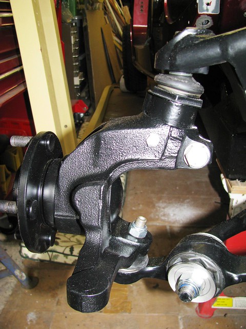
And here they are fitted...

New Front Hubs by Sabrebuilder, on Flickr

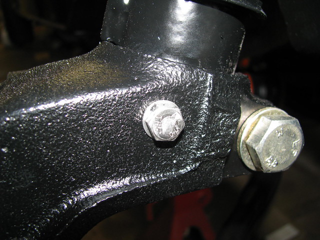
The front hubs and ball joint adaptors were drilled to take an m6 retaining bolt. This is to prevent the adaptor coming out of the hub if the m10 fixing bolt should become loose. This is an IVA requirement.

Front HUB - IVA fix by Sabrebuilder, on Flickr

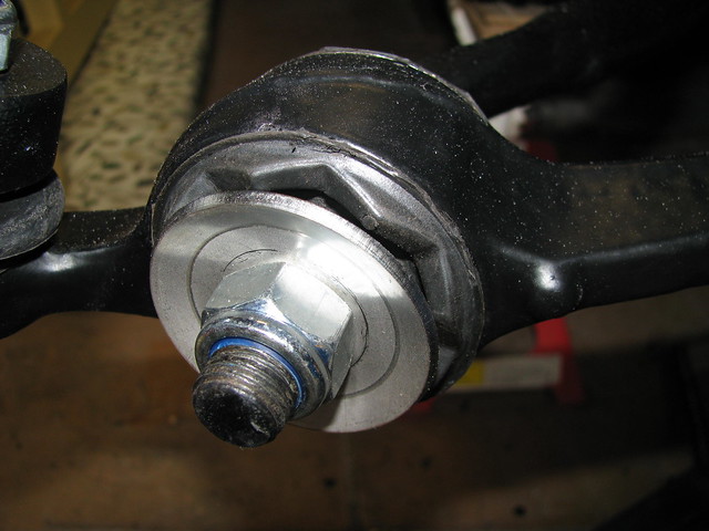
I've reverted back to the original design of the ARB rubber bushes as recommended by Ford. Ford issued a Technical Bulletin stating that the so called Heavy Duty bushes should not be used. According to Ford the original bushes were designed to distort and change the suspension geometry under heavy braking. ( I have also fitted some nice looking stainless steel washers available on ebay.)

ARB bushes and washers by Sabrebuilder, on Flickr

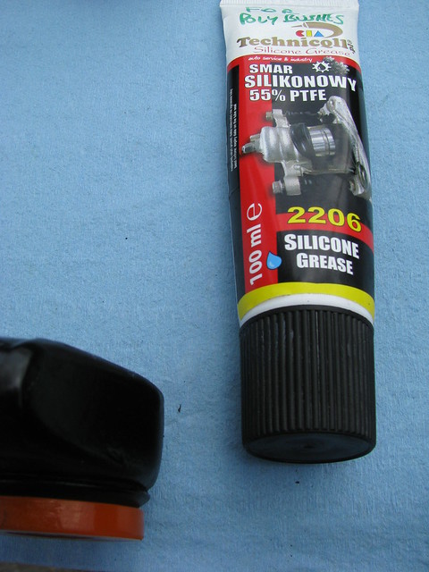
I noticed that when I stripped down the suspension the original silicon grease had dried out and the bushes and ARB were stiff, so during re-assembly I used this PTFE loaded silicone grease.

Polybush grease by Sabrebuilder, on Flickr

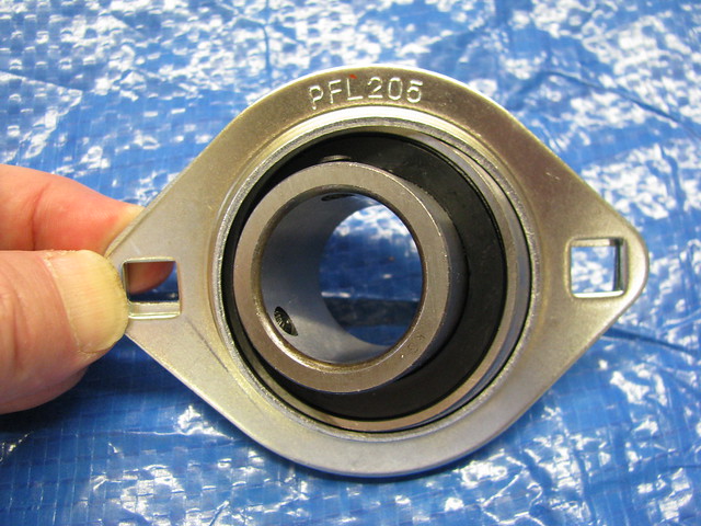
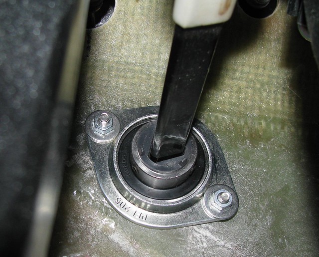
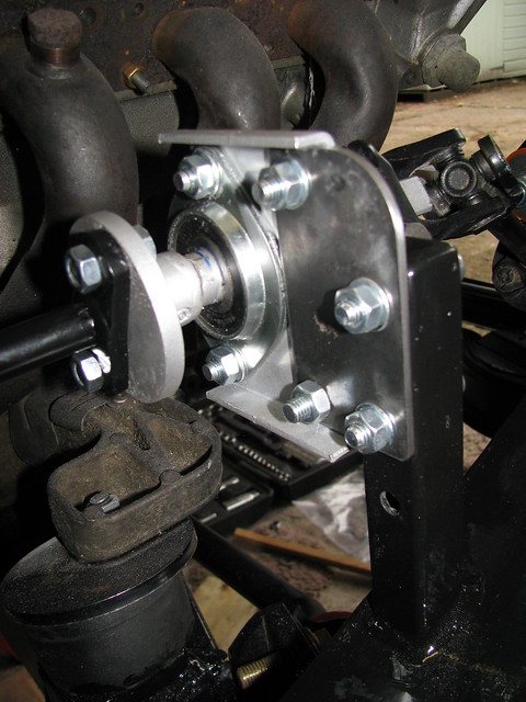
It is a well documented upgrade on Ford based kit cars (and TVRs) to replace the Ford plastic steering column bush with a 'proper' bearing. This pressed steel housed bearing from Simply Bearings is commonly used.

Steering column bearing by Sabrebuilder, on Flickr

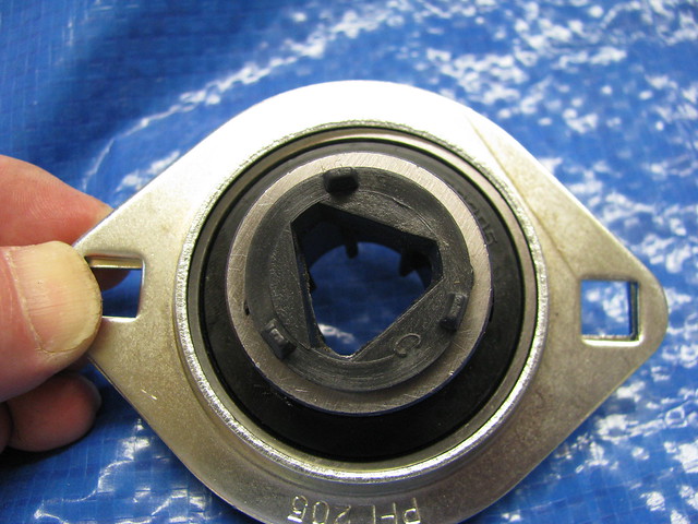
The first step is to fit the triangular plastic part from the Ford bush to the bearing and fix it in place with the two grub screws.

Steering column bearing by Sabrebuilder, on Flickr

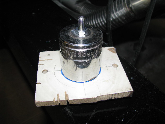
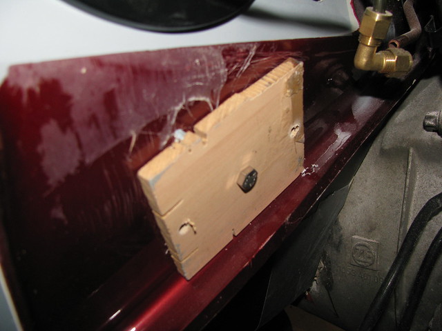
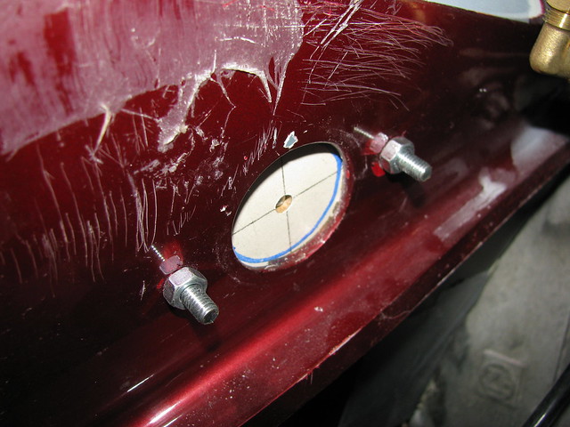
I needed to open up the bush hole in the body to match the new bearing. I made up this alignment tool made from a scrap of mdf and a socket the same diameter of the existing hole.

Steering column bearing by Sabrebuilder, on Flickr

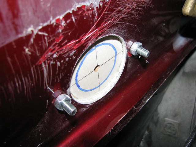
The alignment tool was first inserted in the existing hole and the two mounting holes where drilled through the bulkhead.

Steering column bearing by Sabrebuilder, on Flickr

The MDF template was then bolted to the inside of the bulkhead

Steering column bearing by Sabrebuilder, on Flickr

I then used a hole saw to cut the larger hole concentric with the original.

Steering column bearing by Sabrebuilder, on Flickr

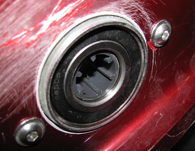
Bearing mounted loosely initially to allow the bearing to take up its natural angle.

Steering column bearing by Sabrebuilder, on Flickr

New bearing from inside the car. Nylock nuts will be used on final assembly.

Steering column bearing by Sabrebuilder, on Flickr

Next on the list is to finalise the steering column and couplings.......


....peter
15 Jul 2017, 10:02pm
Steering

When I first got the Sabre it was fitted with a Sierra manual steering rack and column extension pieces.
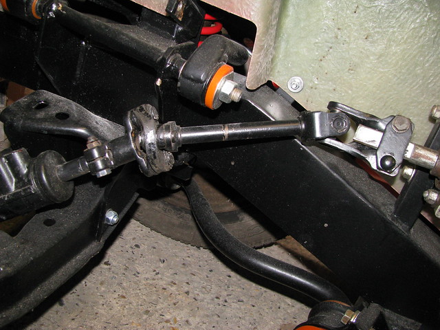
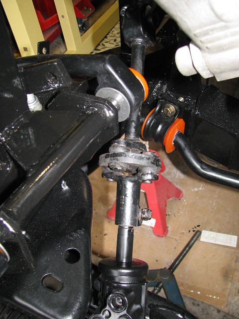
I decided to fit a Granada power steering rack and what I think is the relevant extension piece. When I assembled all this for the first time I was worried that the lower column extension does not align with the steering rack pinion which puts a lot of strain on the rubber isolator. However, looking at another Sabre at the Stoneleigh kitcar show I confirmed that I have the right parts and they are assembled in the right way. The other Sabre also demonstrates this alignment issue suggesting that this is a common problem with the power steering rack. I thought a better alignment could be achieved by re-positioning the fixed midway bearing so I eventually got round to fixing this.

Steering column alingment by Sabrebuilder, on Flickr

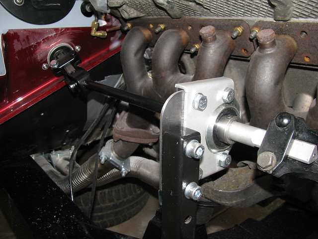
I have re-positioned the bearing upward and inwards towards the engine so that the lower steering coupling is aligned to the input shaft of the steering rack. The upper steering shaft now runs parallel to the chassis rail and approx. horizontal.

Steering intermediate bearing by Sabrebuilder, on Flickr

The lower coupling is now aligned with the input shaft to the power steering rack. This means that there is no additional strain on the rubber disc.

Lower Steering coupling by Sabrebuilder, on Flickr

Rear side of bearing showing details of the extension plate. Not very pretty but functional and very solid.The plate will be painted and fitted with nylocks.

Steering intermediate bearing by Sabrebuilder, on Flickr

next job is the power assisted steering hoses.......


...peter
25 Jul 2017, 7:28pm
Power Assisted Steering

I plan to use a Ford Granada steering rack driven by the BMW PAS pump (because it came with the BMW engine). The BMW pump is conveniently marked with 110 bar output pressure but I struggled to find the spec for the comparable Ford pump.
I eventually found a very helpful Steering Rack specialist company (Western Power Steering) who confirmed that the original pump would have been rated at about 90 bar, but it is the nominal flow that is more important and both pumps would be similar and the BMW pump would be more than capable of working the rack.
I guess time will tell when I get to drive the car!

First, I temporarily refitted the BMW Power assisted steering pump(still in primer) to work out routing of the high pressure lines.

Power Steering pump by Sabrebuilder, on Flickr

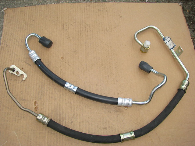
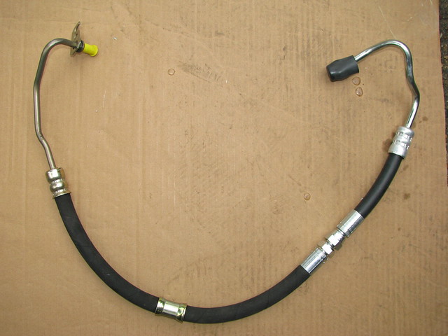
To connect the Ford Granada steering rack to the BMW steering pump I started with a new Ford high pressure hose and a BMW hose.

Power Assisted Steering Hose by Sabrebuilder, on Flickr

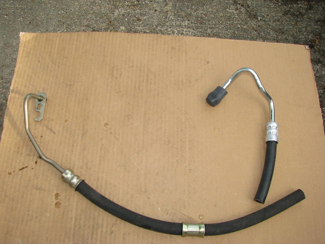
I then cut the pump end off both pipes ensuring that I kept the Ford restrictor fitted in the middle of the Ford pipe. Both ends were slightly reformed to exit at the right directions. I used the BMW rack end as it suited my solution better than the pump end.

Power Assisted Steering Hose by Sabrebuilder, on Flickr

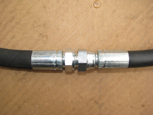
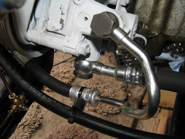
I then visited Hydraulic Components and Systems Ltd in Hemel Hempstead who crimped on a fitting to join the two pipes together. Cost me £20 and they fitted it while I waited. HCS advised that the 'cone' connector is good for an incredible 450 bar so should adequately handle the 110 bar from the BMW pump.

Power Assisted Steering Hose by Sabrebuilder, on Flickr

Power Assisted Steering Hose by Sabrebuilder, on Flickr

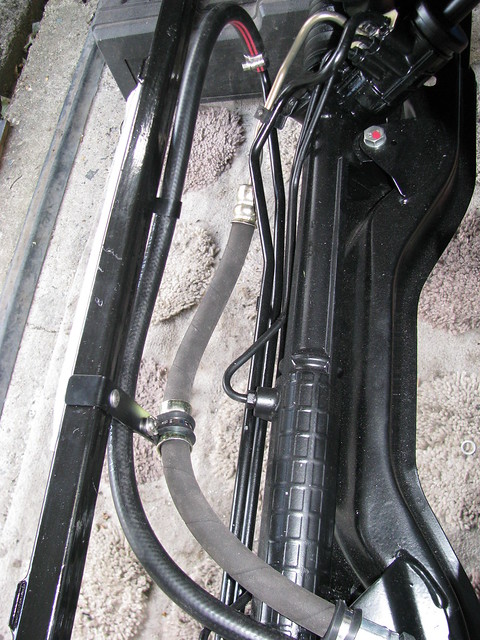
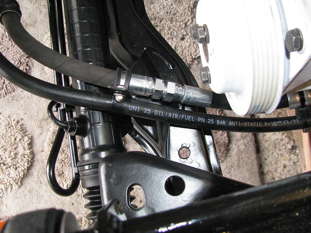
Supply and return hoses supported by front chassis cross rail.

PAS hoses by Sabrebuilder, on Flickr

I made a small support bracket that utilises one of the steering rack mounting bolts.

PAS hose support bracket by Sabrebuilder, on Flickr

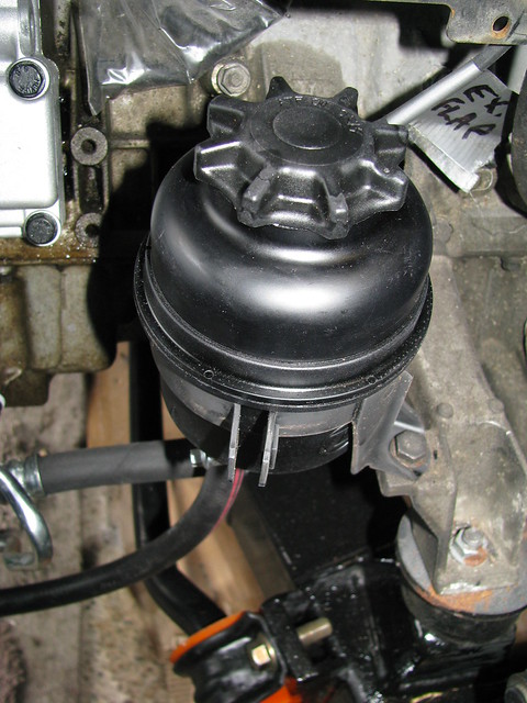
I'm using the BMW PAS reservoir. (Mounting cradle will be painted.)

PAS Reservoir by Sabrebuilder, on Flickr

I've also bought a new 'reservoir to pump' hose. New crush washers to be fitted on final assembly.

PAS hoses by Sabrebuilder, on Flickr

Can't wait to see if all works!! :lever:

So another job ticked off the list..........

Next up will be fitting the front brakes and pipes.......

...peter
25 Jul 2017, 8:36pm
Nice work :)
2 Aug 2017, 8:38pm
Front Brakes

Patrick wrote:
Nice work :)


Thanks, Patrick.

--------------------------------------------------------------------------------------

Having rebuilt the front suspension and sorted the PAS steering, I could now move on the fitting the front brakes.
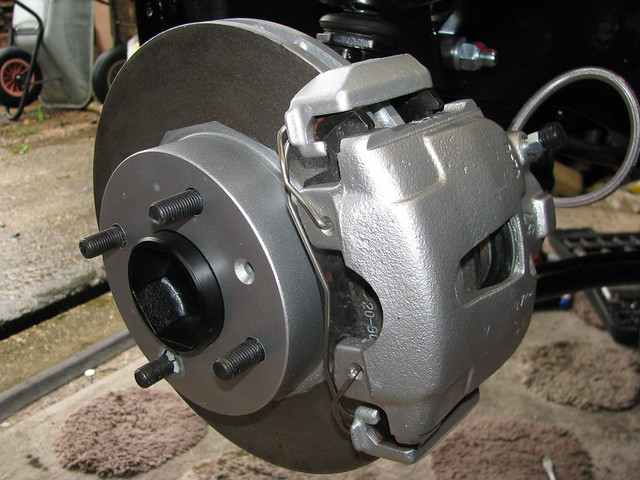
I started by installing the brake discs and the calipers that I re-furbished back in the winter. The discs were new when I bought them but it's been so long ago they have a bit of surface rust.

Brake disc and caliper by Sabrebuilder, on Flickr

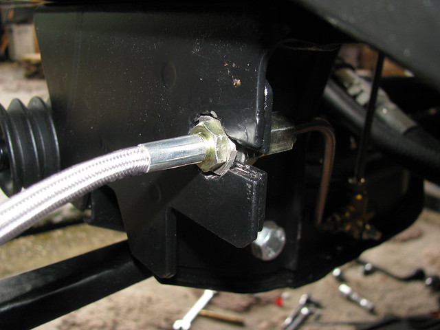
I'm using Goodridge flexible hoses but the front hoses have the wrong size fitting for the Ford crossbeam mounting point. I tried using a nut each side of the mounting but that made it too short for the pipe fitting the other side. So I made up a stainless steel hexagon shaped washer which worked a treat.

Front Brake Flex hose by Sabrebuilder, on Flickr

I've mounted the front tee fitting on the front crossbeam.

Front Brake pipes by Sabrebuilder, on Flickr

Brake pipe will be p-clipped to the chassis rail when I have the engine out for painting.

Front Brake pipes by Sabrebuilder, on Flickr

Technically speaking, once this pipe is p-clipped to the chassis rail, the IVA requirement of fixings every 30 cm would be met but the brake pipe did look a little vulnerable so I made up an additional support tab.

Front brake pipe support by Sabrebuilder, on Flickr

Tee fitting to offside brake flexi.

Front Brake pipes by Sabrebuilder, on Flickr

..........to the nearside brake caliper.

Front Brake pipe by Sabrebuilder, on Flickr

So that's the complete Brake System finally completed awaiting bleeding after the final body tub fitting.

Next up will be the cooling system........

...peter
2 Aug 2017, 9:02pm
Great work , can I ask were you able to use existing holes for your T fittings and P clips ?

My vehicle is a simple rebody so no IVA.
3 Aug 2017, 8:12pm
paul_n wrote:
Great work , can I ask were you able to use existing holes for your T fittings and P clips ?.


Thanks for the feedback, Paul.
No, these pipes take a different routing to the original build so all the holes were newly drilled.
26 Oct 2017, 7:27am
Cooling

Well, I've been a little remiss in not updating my diary so i'll try and catch up over the next few days.
First 'catch-up' update is about the cooling system which I tackled back in August.

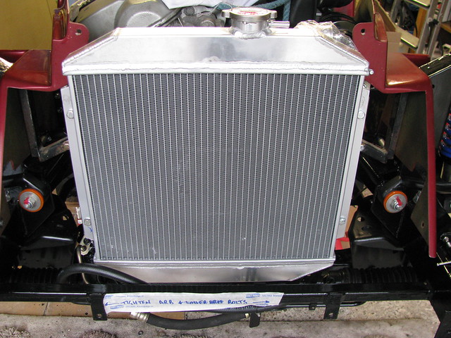
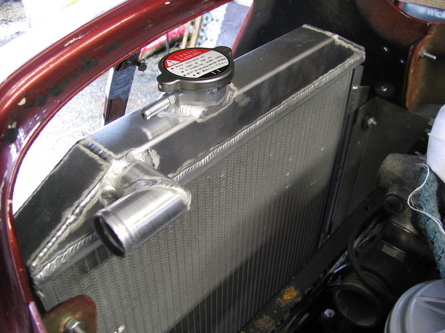
I'm using an alloy radiator designed for a Ford Escort RS2000 Mk2. It's the same size as the one I used in my Marlin Sportster so i know it works well with the BMW engine.

Radiator by Sabrebuilder, on Flickr

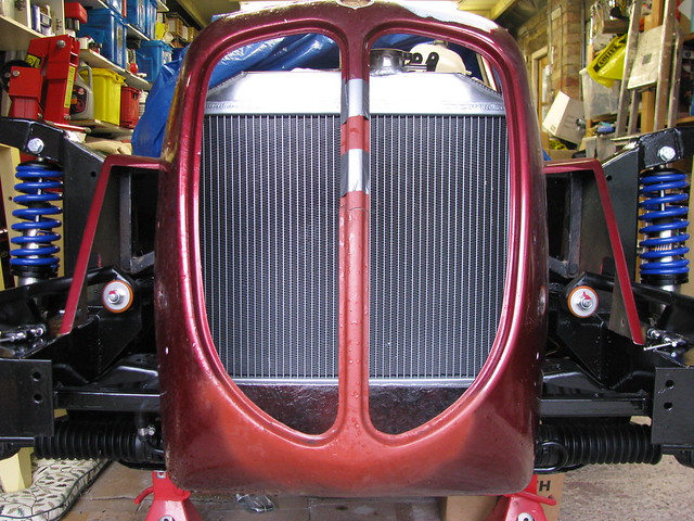
The Escort radiator fits remarkably well behind the Sabre's nose.

Radiator positioning by Sabrebuilder, on Flickr

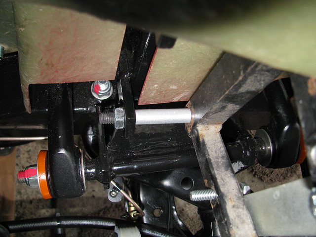
Because I'm fitting a straight 6 BMW engine I had to move the radiator support frame forward by about 65mm. The support frame and brackets are standard parts supplied by Royale. I've put spacer tubes between the radiator support frame and the original chassis mounting tabs. Further strengthening tabs were be fitted but not shown here.

Radiator Frame spacers by Sabrebuilder, on Flickr

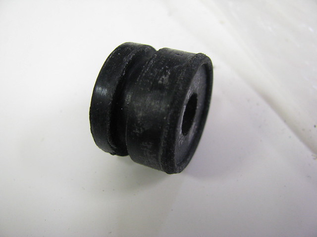
After extensive internet searching I eventually found these really neat grommets on ebay.

Radiator mounting grommet by Sabrebuilder, on Flickr

M8 bolt through rubber grommet.

Radiator mounting by Sabrebuilder, on Flickr

Despite mounting the radiator much further forward than John Barlow designed it's still possible to reach and remove the radiator cap.

Radiator clearance. by Sabrebuilder, on Flickr

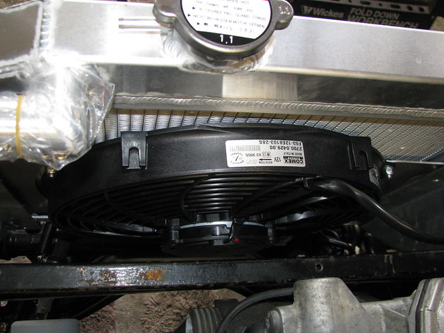
13" Comex fan, supplied by Revotec, mounted on the back of the radiator.

Radiator Fan by Sabrebuilder, on Flickr

Previously I've used those plastic tie wrap type mounts which damage the radiator so this time I used the Revotec supplied mounting brackets.

Radiator Fan by Sabrebuilder, on Flickr

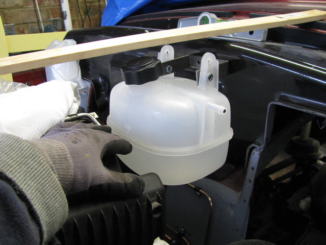
I've chosen this MG Rover 25 ZR coolant header tank (PCF000161). Here I'm lining it up to check clearance with the engine and bonnet top represented by the piece of wood. (You can tell it's summer as I've got my jumper and gloves on :-) )

Coolant Header Tank by Sabrebuilder, on Flickr

And that's about as far as I got with the cooling system. Pipework etc will be completed on the final assembly following painting and fitting of the central body tub.

That's all for now, more updates to follow soon.....

...peter