This is a read-only archive of the old Madabout Kitcars forum. New posts and replies are no longer possible, but every thread is still here to browse and read.
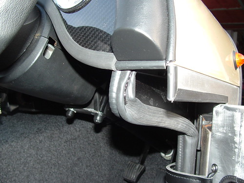
It's been a busy weekend, getting high on glue fumes and finally fitting carpet and rubber matting:
That's another job ticked off.
I've left the door seal over-long near the dash, as I'm not sure how to finish it off - either cut it off level with the end of the sheet metal, bend it up and cut it off after it's gone round the corner or cut it off short and not bother extending it along the top most edge of the door. Suggestions?
On your last question, I managed to persaude mine to go round the last corner and I think I then glued it in position.
Looks better in real life as the flash in this picture has accentuated all the different 'blacks'.
(This picture was hiding in my 'Seats and Seatbelts' set for some unknown reason.)
Thanks Peter - My back is aching like hell, and I can't feel the tips of my fingers (makes typing interesting ) - But I'm very happy with how it's turned out.
Pete - how long are your door check straps? I've got some staples and some black nylon webbing that I'm going to use (which will get covered in the red leather cloth), but I'm not sure how long to make them.
Also - does anyone have any handy hints on making gearstick gaitors? The one I got from the seat place was useless - too big / tall, and the hole that the stick passes through was off centre. I tried cutting it to make it fit, and fudged it up completely.
Pete - how long are your door check straps? I've got some staples and some black nylon webbing that I'm going to use (which will get covered in the red leather cloth), but I'm not sure how long to make them.
My friend Rob came round tonight, and we prototyped the low fuel circuit. I now have all the correct values for the components to get a 60 second delay before the lamp lights.
The video shows it in action - the delay has been reduced to about 4 secs for testing purposes. It turns on at about 1/8th of tank, set by a pot that determines the threshold. Another pot simulates the sender - turning it past the threshold, the lamp lights once after the preset delay, and immediately switches off if the the sender input goes above threshold again.
I'll be posting up the completed circuit, and Rob will write a more thorough explanation of how it all works. It looks as if it'll be simple to modify the circuit for any sender / meter combination as well, simply by changing the values of some resistors on the input stage of the circuit.
My friend Rob came round tonight, and we prototyped the low fuel circuit. I now have all the correct values for the components to get a 60 second delay before the lamp lights.
The video shows it in action - the delay has been reduced to about 4 secs for testing purposes. It turns on at about 1/8th of tank, set by a pot that determines the threshold. Another pot simulates the sender - turning it past the threshold, the lamp lights once after the preset delay, and immediately switches off if the the sender input goes above threshold again.
I'll be posting up the completed circuit, and Rob will write a more thorough explanation of how it all works. It looks as if it'll be simple to modify the circuit for any sender / meter combination as well, simply by changing the values of some resistors on the input stage of the circuit.
I've checked and triple checked everything on the board, but it only seems as if the first stage of the circuit is working (the first comparator). At and above the set threshold, I get a solid 9v on pin 1. On the second stage I get 8ish volts on pin 6 and milivolts on pin 5, resulting on nothing on pin 7. Nothing on 7 means no transistor switching the light on...
Can someone do a sanity check on this for me? Rob's off on holiday in austria now, so he's more interested in skiing than debugging a circuit via SMS.
Finalised circuit, which I know works from the prototype:
Track brakes are denoted by the red squares. Ignore the markings on the transistor in the board layout - i've labeled the pins the wrong way round, but they are correct on the real thing.
First thing to check on an PCB when it doesn't work are:
1. Dry joints? (How's your soldering Jason ;-) )
2. That the tracks are actually broken where they are supposed to be. If you just used a hobby knife it's easy to leave a small piece of copper in place.
3. Any accidental solder bridges
All breaks have been done with a track cutter, and they look clean under a magnifying glass.
Solder bridges - it looks clean.... I did run a soldering 'pick' down the gaps between tracks and didn't meet anything but I'll double check.
Ok - that's the obvious out of the way. It can now only be either a layout error or component failure. Components are pretty robust nowadays so I would double check the layout first.
Never mind, got it working now - when we did the vero-layout we missed a track break. I just discovered that there should be one row D, column 23. D3 was connected to R13 and the base of the transistor, which wasn't right at all!
Broke the track there, and lo and behold it all works. Yay!
You will probably/possibly need to cover the lower spring plates. Mine failed on this. I used a universal U/J boot cut down. Also be carefull with the large lock nuts on the upper suspension arm. Mine failed even though they were covered. In the end I had to knock off the corners with a file before covering them with shrink. Spanner still fits!
Thanks for the tips - I'll see if I can pick up some UJ boots. Any particular size?
I got mine from the local motor factor. They were only about a fiver as I remember (far cheaper than a re-test) It seemed to be one size fits all. They are made of some very strange rubber with elastic properties so you can stretch them to fit any UJ (Or Marlin spring).
You need to cover the sharp edge of the spring plate that faces down which is just about contactable by the test sphere if you have a zealous tester....
When fitting the flexible UJ boots (not that you are, but I used them to replace the boots on the driveshafts of the Cabrio) you turn them inside out and slide them over a very large greased cone.


 ) - But I'm very happy with how it's turned out.


