MadaboutKitcars

This is a read-only archive of the old Madabout Kitcars forum. New posts and replies are no longer possible, but every thread is still here to browse and read.

Swifty's Navigator

19 Oct 2014, 7:22pm
Swifty, does the Corsa shaft have 9/16" 36 spline connectors at each end?
19 Oct 2014, 7:31pm
Oxford Nope its a pre fabricated unit that can't be dismantled so in the future if one of the UJ's requires replacing then the whole unit will have to be re placed. The profile of each UJ fixing is 18mm o/d with two flats at 14mm across, once i make the adapters ill post some pictures on here for future reference. The adapters will be very straight forward to make if you have access to a lathe.

Also it has a facility to collapse if involved in an accident.
19 Oct 2014, 7:34pm
Utterly superb work as ever!... those gaps on the rear arches really bug me!

Cant wait to see your car all finished!... loving black wires with chrome spinners too.... top of the range Sir! ;)
19 Oct 2014, 8:22pm
great work ...swifty this is going to be a fab car ..can not wait for next bit ...going to look very good in colour ...some very nice bit 's top job
19 Oct 2014, 9:58pm
Steering

Brilliant timing! About to tackle the steering column myself & just got access to a lathe!

Looking forward to the next installment:popcorn:
20 Oct 2014, 4:48pm
Swifty - Lots of good progress there. :cool:

What distance from the tyre to the rear arch did you end up with?

Good luck, Paul. :)
20 Oct 2014, 7:56pm
Paul 40 to 45mm.

I've still to tidy each arch so that the curve has a smooth even look plus the leading edge is to blend in as i want the side sub frame box sections to be hidden by the body and for the lower sill to run parallel to the rectangular box section.

I am still trying to figure out the best solution for the boot hinges so that the lid lifts clear of the surrounding body which is curved from the near side to the off side, had this area been flat then it would not be an issue.

More thought required.
28 Oct 2014, 10:35pm
The steering is eventually finished although it has worked out differently from what i had in mind. The UJ section i took out of the corsa did not fit as anticipated so i had to leave it and come back to it another day.

Will post pictures in the next couple of days.

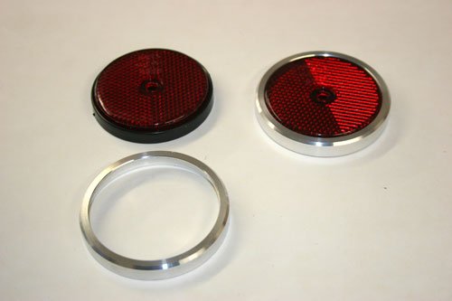
Made a few bits to finish off the rear reflectors.

IMG_4786.jpg


The reflectors came with a black plastic rim that does not look in style with the fifties race car i am trying to emulate so i decided to turn two ally covers which fit very snugly over the plastic rim, these were turned on a manually lathe from stock 70mm ally bar, its probably pointless putting the dimensions on as it will depend on where you buy the reflectors from but if you need the dimensions drop me a line.

The left hand reflector is as standard while the right hand one has the ally trim fitted. I am going to do the same for all the light fittings so that they match.

IMG_4788.jpg


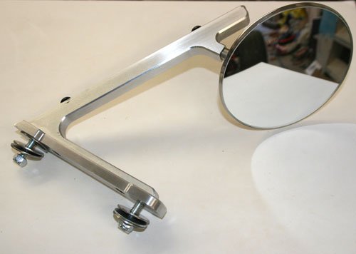
Finally finished the screen and rear view mirror support, I've gone for a 4 inch round stainless steel mirror in keeping with the fifties style.

IMG_4784.jpg
IMG_4785.jpg


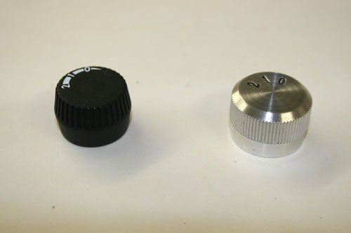
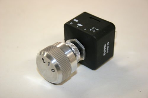
The heater i bought came with a plastic control knob which again does not look like something from the fifties so i decided to make a control knob out of ally. Used 30mm ally bar turned on a manual lathe, internal recess bore to match the switch shaft which has a hex profile.
Milled a hex profile on round silver steel bar with a dividing head, this was used as a punch to match the switch shaft hex profile, the knob was held in the lathe chuck while the hex profile silver steel bar was held in the tail stock chuck and wound into the internal bore of the knob to cut the hex shape, a knurling tool cut the serrated edge plus all edges are chamfered.

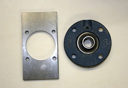
Machined a steel plate to match the self aligning bearing mounts etc, this has been welded into the front sub frame to both align and hold the steering column shaft, more pictures to follow.

IMG_4780.jpg


Machined plate and bearing.

Well that's it for now see you all soon.
29 Oct 2014, 12:11am
This mans a genius!
29 Oct 2014, 8:43am
pretty pretty..... :)
29 Oct 2014, 8:44am
Good skills! Some nicely turned out billet parts there (pun fully intended). Looks like you could open your own 'rod detailing business if you so chose. :)

You might want to make a couple of brackets similar to the rear view mirror support for side mirrors as raising them up is the only way to get them anywhere near the height they are on a conventional car and actually see anything out of them -


Keep up the good work!
29 Oct 2014, 9:39am
Swifty - You skills and attention to detail really are jaw dropping. :cool:

Good luck, Paul. :)
30 Oct 2014, 7:30pm
DapperDan , Dave and Paul Thanks for the comments

MrT May be when i retire i may set up a small machine shop with a cnc bed mill to do one off bespoke parts. This is something i have thought about after seeing your side mirror mounts, so will definitely look into how i can possibly lift the mirrors up.

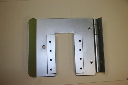
Made a base out of 3mm ally plate for the fuse board to mount onto.

IMG_4794.jpg


The cut out is clearance for the wires that attach to the bottom of the fuse board with a couple of spacer's to lift the fuse board up slightly. The hinge is to gain access in the future.

IMG_4800.jpg
IMG_4799.jpg


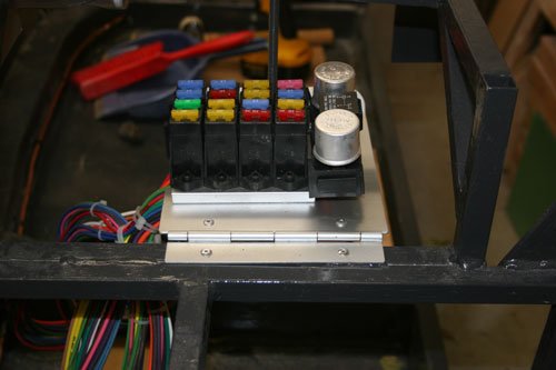
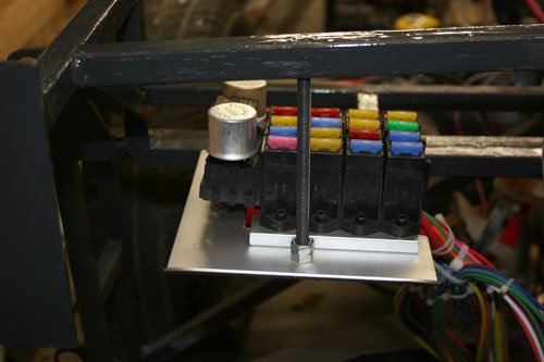
Plate and fuse board in position on the passenger side behind the dash board area, a length of 8mm studding welded to the 20mm box section is used to lock the plate in position with a wing nut to drop the plate down for maintenance, this can be seen in the second image.

I am thinking that the safest position to run the wires from the front to the rear of the car is on the passenger side down in the sill area, I've bought a length of black plastic conduit that i will put in the sill area before back filling with expanding foam, the tube will allow in the future if needs be any cables to be replaced may be a bit over the top but while at this stage it easier to do now.
30 Oct 2014, 7:39pm
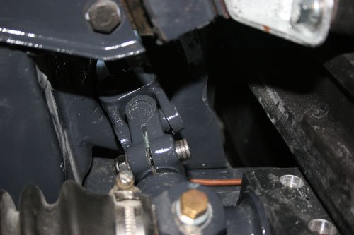
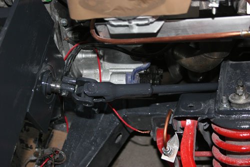
A couple of pictures of the steering column.

IMG_4789.jpg
IMG_4790.jpg


Left hand image is of the UJ joint that i attached direct to the original steering box. Right hand image is of the second UJ just after the shaft passes through the bulk head. The steel plate with the self aligning bearing is the one i posted a picture of in an earlier thread.

IMG_4791.jpg


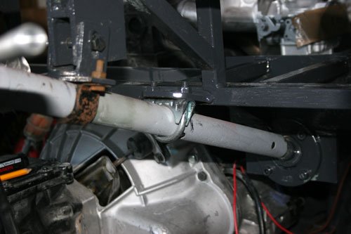
This is the inside of the steering column, the rusty bracket is the original column mount bracket and the second bracket is an exhaust U clamp bought from Halfords, i will be painting it to match the other box section paint.

IMG_4795.jpg
IMG_4798.jpg


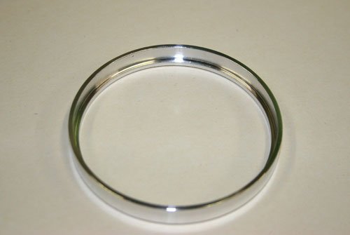
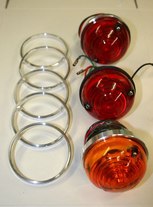
Made another eight ally rings to finish all the light fittings off, the first image is of the inside of the ring so you can see whats required, I've machined a small lip that sits on the black rubber light base.

Well that's it for now see you all soon.
31 Oct 2014, 4:39pm
Swifty - There are certainly no short cuts being taken on your build. :cool:

Good luck, Paul. :)
2 Nov 2014, 7:40pm
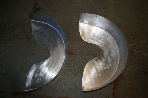
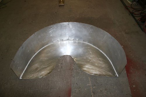
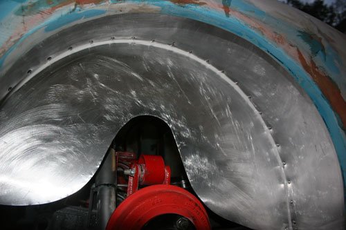
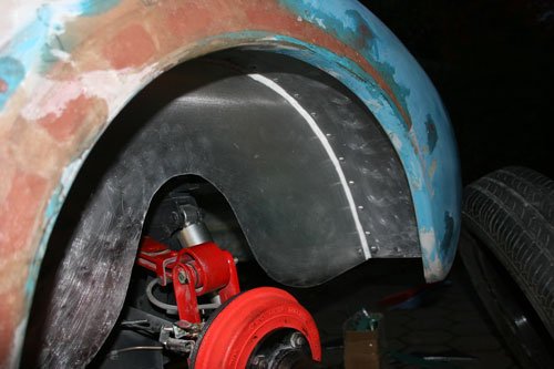
Made a couple of inner rear arches today out of 1mm ally sheet.

IMG_4803.jpg
IMG_4804.jpg


Inner arches keyed and ready to etch prime and top coat. Sealer applied around the inner join for good measure. Hopefully i have left enough clearance for the rear suspension movement.

IMG_4802.jpg


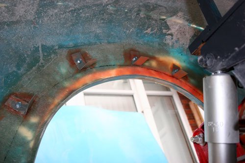
Used brackets to help position and attache the ally wing to the fiberglass, these have been pop riveted to the body and once i am happy with the rear arches i will seal and glass them to the body.

IMG_4805.jpg
IMG_4806.jpg


Picture of the arches temporarily fitted as i need to remove them to spray paint each one. I intend to seal the gap between the arch and body with sealer then glass the top face of the arch to the body, i may even put a couple of strengthening bars from the rear sub frame to the side ally plates.

Well that's it for now see you all soon.
3 Nov 2014, 10:28am
v.nice! Exactly what i am planning on doing :)

In case it's of use/interest, when i made the Ply ones on my Sammio i did end up adding bracing from them back to the frame as they weren't as rigid as i'd liked when only bonded to the shell.
4 Nov 2014, 12:42pm
I think it may well be wise to fit a couple of strengthners to the side and top arch for good measure may be bend some round tube to match the arch profile, , this will be easier to do before the body is finally fitted so will post the pictures when complete.
4 Nov 2014, 9:13pm
Swifty, Google Lucas PCL6, its available with or without the ignition key.

Mac
4 Nov 2014, 9:19pm
Cheers Mac, do you know if the genuine Lucas switch is stamped with an id number, the reason i ask is i don't want to buy another sub standard switch which mimics the Lucas or is from China.

Hopefully the Lucas is of good quality?
4 Nov 2014, 9:21pm
This is where I got mine, not cheap but you pay for good stuff I guess!
9 Nov 2014, 7:35pm
Made some steady progress this weekend.

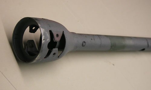
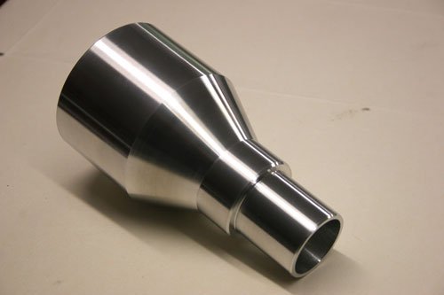
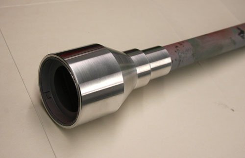
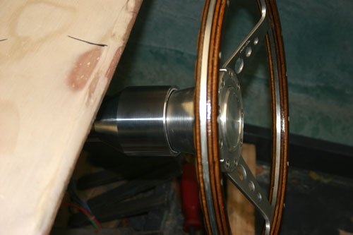
First off i turned a cover to slip over the steering column to hide the original tube plus i wanted to get rid of the original spitfire steering column plastic cover.

Turned on a manual lathe from a 80mm round billet of ally, 25 degree taper to match the original column. The lower portion of the column is hidden by the dashboard so the ally cover just goes beyond the dashboard.

IMG_4814.jpg
IMG_4813.jpg


Original tube with the lugs bent in to allow the new cover to slip on.

IMG_4811.jpg
IMG_4817.jpg


The ally cover in place, i think i now need to make an ally insert ring to fit into the top to hide the lip of the original steering tube as you can just see it and it does not look right, the original tube will have to be slightly trimmed to allow the ring to push fit into the new cover.


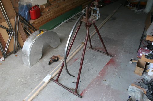
Also finished the rear internal arches by adding a strengthening ring bent from 20x20mm steel box section with a brace welded onto the sub frame.

IMG_4818.jpg


Used a bending rig to match the rear arch curve. The box section was then pop riveted to the ally arch and a little sealer used for good measure.

The rear boot has also been fitted and welded into place which means the shell can longer be removed so the next thing is to bond the shell to the sub frame etc.

My plan is to glass the outer sill area to the floor section then to back fill the internal sill area with expanding foam but place plastic conduit into the sill void before using the foam, the conduit is for the cables to go to the rear of the car plus the battery is fitted into the boot so i have to bring the main battery cable through to the front. The cable is a pretty hefty 25mm squared cable capable of handling up to 180 amps, i had the amp meter on the cable while cranking the engine and it pulls 150 amps so this cable will be ok with a voltage drop of .8 volt.

Once the foam has gone off i intend to glass over the top to bond the shell to the inner floor section.

Well that's it for today see you all soon.
10 Nov 2014, 4:32pm
Swifty - I thought your arches were pretty good, but that steering column cover is simply amazing. :hail:

It sounds like you are really making great progress getting the body shell permanently fixed. :cool:

I normally say good luck, but luck doesn't appear to play any part in your build.

Cheers, Paul. :)