|
|
| Seven Style builds Westfields, Caterham, Dax Rush, Luego, Robin Hood, Tiger, Locust, MK, RAW, Quantum, you name it, you're building it, share it here. |

16th October 2023, 06:56
|
|
Senior Member
|
|
Join Date: Nov 2012
Posts: 845
|
|
 Fourth time lucky?
Quote:
Originally Posted by Mick O'Malley

I'm still wrestling with how best to mount the engine. My previous imagined solutions would have resulted in its being either too high or too low, and probably insufficiently strong. I'm currently chopping some square plastic down pipe as a cross-member template for some 1.5" box. Time will tell!
|
I'm now happy that my Moss Monaco next door is, after yet more minor fettling, fully operational, so I've turned my attention back to the poor neglected Phaeton. Having abandoned the above plastic pipe abomination as being too flimsy, I dreamt up the idea of a 'virtual engine' in the shape of a lightweight template that I can much more easily dangle in the engine bay whilst cutting steel for mountings. I can also easily transport it when the day comes to take the frame to my welding buddy for the various prepared bits to be stuck together.
Having purchased half a metre of inch square aluminium box, I transferred the mounting rubbers from the engine block to the Talbot Sunbeam cross member and, after lots of careful measuring and marking, fetched the hacksaw to it for the two birdsmouth cuts. I lay it across the mountings, bending it a little at a time until it lay snugly and symetrically. I then drew around the mountings' metal plates, put the gizmo in the vice, and lay a removed mounting on the marks to draw where the bolt holes were needed. I super carefully drilled through the box and firmly bolted the whole thing back together. It sat perfectly.

All that's left for its completion is natty little fishplates pop rivetted on each side of the birdsmouths to preserve their angles, its removal from the crossmember c/w the mountings, and my creation will be ready for engine bay action.
Regards, Mick

|
17th October 2023, 16:31
|
|
Senior Member
|
|
Join Date: Nov 2012
Posts: 845
|
|
 Funky Fishplates Finally Fitted
Digging out my Machine Mart aircraft quality tin snips, and searching through my scrap metal heap, I assembled the necessary, made a cardboard template and cut out two fishplates. I'd intended four but decided that was overkill. I drilled their rivet holes and G clamped them to the box section. After carefully and very lightly centre punching the box through the holes, I drilled and rivetted them in place. All that was then left was to remove the cross member and dangle my creation from a length of the ever-useful paracord for a photo-call.

I'm now reasonably confident that with its easily manipulated assistance I can accurately fabricate mountings. It's certainly considerably less unwieldy than the engine it represents!
Regards, Mick
|
27th October 2023, 15:00
|
|
Senior Member
|
|
Join Date: Nov 2012
Posts: 845
|
|
Virtual Engine Debut
In yesterday's sunshine, after a short drive in the Monaco, I decided to dangle my gismo from the frame's top side rails in position in the engine bay. It was quite a fiddle to get it aligned in all three planes: fore and aft and laterally weren't too tricky but the correct height (as determined by my fruitless earlier attempts to utilise the Talbot's cross-member) took a great deal of patience and not a few profanities  . .
It was then clear that the new mountings would need to sprout from the diagonal horizontal 1.5" square frame braces, so I dug out my length of matching section steel box, made a card template of the angle needed for the mount to protrude parallel to the car's lateral axis, and carefully hacksawed one end of a suitably oversized 'one mounting' length and offered it up. It was OK. Knowing my concentration limits, and tendency to commit schoolboy errors I called it a day, pleased with the tiny progress increment  . .
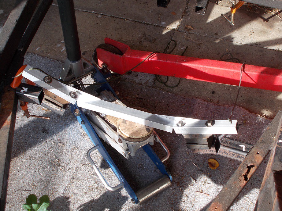
This morning I pitched in again, offering up my stubby blank and imagining how it would best mate with the gismo - a downward angle was clearly needed. More careful measuring, a saw cut through the top three sides of the box, and judicious bending with the aid of another card template had the engine end sitting at the correct angle. I marked where the bottom mounting rubber's stud met the box and drilled a slightly oversized hole (which I imagine will eventually need to be slightly oval). I then cut off the redundant end length at 45 degrees which both tidied it and provided access for the stud's nut to be tightened. Bolting my creation in place I took the picture below.

The open cut will obviously need a fillet, TDW's forty year old diagonal beefing up, and a diagonal strut to another frame member for full belt and braces effect. I didn't check to ensure the gismo had stayed central so this effort may have to go down as a prototype. However, if necessary, I have more than enough box to remake it as well as its mirror image twin.
Regards, Mick
|
28th October 2023, 14:18
|
|
Senior Member
|
|
Join Date: Nov 2012
Posts: 845
|
|
 Some more progress...
After a grey start to the day, the sun appeared at around ten tempting me down to the cave for further metalwork. Careful measuring revealed that yesterday's effort would indeed be merely a prototype, as it was a couple of centimetres too short to ensure the engine sat centrally. To cut the box for its replacement, I decided to use the hacksaw rather than the disc cutter, as I can no longer hold the latter steadily enough for sufficiently accurate cutting. A bit of a pain but necessary. My first cut was angled as per the template, one mountings length from the end of the length of box, so it only needed doing once. Yesterday's effort was also a little short of bearing area where it met the mounting rubber, so I re-positioned the birds mouth cuts a little to compensate and opened them up using the prototype as a template. The bends will doubtless need tiny tweaks so I'll leave cutting the fillets until then.
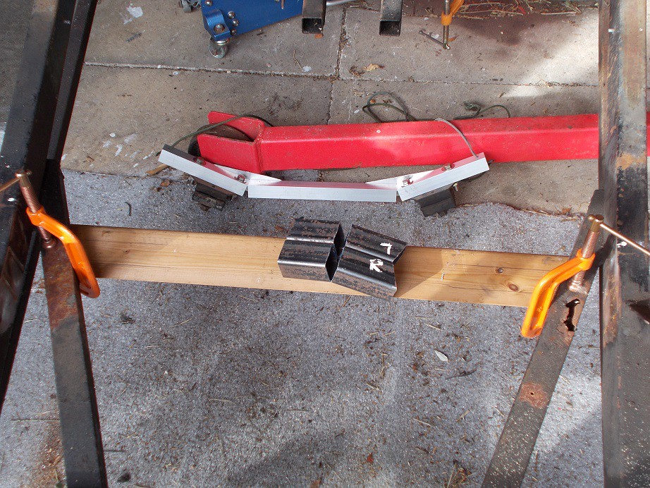
I clamped a cut to length piece of surplus skirting board under the frame and marked it at the ends, and where the mountings would sit. Tomorrow I'll put it on the bench, sit the mountings on it upside down, lie the gismo next to it, and mark where the holes will need to be drilled. I'm certain that these will need to be slotted a little but I have a burr bit for the drill so it shouldn't prove too irksome. Note the L&R in correction fluid - I know what I'm like!
Regards, Mick
|
29th October 2023, 19:53
|
 |
Senior Member
Enthusiast
|
|
Join Date: Mar 2005
Posts: 3,079
|
|
Enjoying your updates, thanks for posting them 👍
|
30th October 2023, 12:29
|
|
Senior Member
|
|
Join Date: Nov 2012
Posts: 845
|
|

Yesterday I delivered a couple of post items to my pal who lives on a 'continuously cruising' Dutch Barge. This involves a few miles' drive, a small hike down the towpath, and putting the world to rights at length over cups of coffee. By the time I got home my get-up-and-go had got up and gone, so I took the afternoon off. This is the tub as photographed by its previous owner.

This morning I pitched in with marking and drilling the necessary holes in the mountings. Reference to those in the old cross member guided me in how long the ovals needed to be and it proved a doddle with the box g-clamped to the workmate. In my excitement at putting the bits together and offering them up to the frame I neglected to take step-by-step pictures. Balancing my creation on the trolley jack, loosely clamping one end to the frame (the cave's floor is far from level!), and sliding the mounts outwards on their oval holes until they butted up to the diagonal frame members resulted in an encouragingly acceptable fit. Miracle!
Thoroughly pleased with this outcome I quit while I was ahead .
Regards, Mick
p.s. Many thanks Peter for encouragement!
|
7th November 2023, 07:17
|
|
Senior Member
|
|
Join Date: Nov 2012
Posts: 845
|
|
Cardboard Assissted Design :)
Since my last post I have made the 'spanner access' diagonal cuts to the inboard ends of the mountings and pondered how their proposed diagonal braces up to a frame tube could be made. I found a rusty old piece of 1" angle and offered it up to TDW's side diagonal frame brace. The old mountings were braced to these so I reasoned that mine would be OK. I bought on Ebay a one metre length of 30x30x3mm mild steel angle (which the delivery guy simply rammed though my letter box) and wondered how best to cut the necessary angle where it met the mounting. Its top end will simply rest over the box section diagonal, possibly needing a belt with the lump hammer to open its angle up a little with it resting against one jaw of the open vice. I hit on the idea of making a cardboard template, found some stout card, cut it 60mm wide to the length-ish needed, and folded it to replicate the angle. Snipping off small amounts at a time with repeated offerings-up soon had it nestling snugly at both ends.

The mounting was both tied on and bridged to the frame with a magnet to ensure its correct location.
Together with the rear seat belt mounting frame, the rear fuel tank support, and the headlamp mounting stubs, that's now all the metal cut for the welding sortie, towed behind the Jazz using the Dutton towing gismo. I discovered the other week that there is a legal requirement to have a safety line in case the massively strong towball should snap off . I bought and fitted one to the gismo as the frame as towed will probably weigh almost 100 kilogrammes/two hundredweight. One can't be too careful...
I scan Ebay each morning for a Hillman Imp sport cylinder head and yesterday I snapped up for a thoroughly acceptable sum a tubular steel sport exhaust manifold for said head. I'm sure this can be pressed into service with a side silencer for that distant 'firing up' day
Regards, Mick
|
|
Currently Active Users Viewing This Thread: 1 (0 members and 1 guests)
|
|
|
 Posting Rules
|
You may not post new threads
You may not post replies
You may not post attachments
You may not edit your posts
HTML code is Off
|
|
|
All times are GMT +0. The time now is 16:45.
|


 Hybrid Mode